Lillbacka Powerco FINN POWER CM75PH User manual


3
Copyright 2018by Lillbacka Powerco Oy. All rights reserved.
Translation of the original instructions.
No part of this documentation may be reproduced, copied or transmitted in any form, or by any
electronic, digital or other means, without permission in writing from Lillbacka Powerco (referred to
herein as the “Company”). This includes photocopying and information storage and retrieval
systems. The material in this documentation is subject to change without notice.
Keep this manual for future needs.
The machine has been designed for cutting hydraulic hoses. Lillbacka Powerco shall not be held
liable for any product which has been cut with the machine. The machine has been designed to
operate in room temperature, in dry indoor conditions and in sufficient illumination. Using the machine
for any other purpose is not allowed without written consent from the factory.

4
CONTENTS
CONTENTS ........................................................................................................................... 4
GENERAL ............................................................................................................................. 5
TRANSPORT ...........................................................................................................................................5
STORAGE...............................................................................................................................................5
MOUNTING .............................................................................................................................................5
HELP PROTECT OUR ENVIRONMENT ............................................................................... 6
DISPOSAL OF THE PACKING MATERIAL......................................................................................................6
DISPOSAL OF YOUR OLD MACHINE ...........................................................................................................6
WARNINGS........................................................................................................................... 6
GENERAL ............................................................................................................................................6
WARNINGS........................................................................................................................... 7
GENERAL...............................................................................................................................................7
DANGER ZONES......................................................................................................................................8
COMMISSIONING................................................................................................................. 9
ELECTRICAL CONNECTION.......................................................................................................................9
COMPRESSED AIR CONNECTION ..............................................................................................................9
OPERATION ....................................................................................................................... 10
CONTROL IDENTIFICATION.....................................................................................................................10
FUME REMOVAL....................................................................................................................................10
CONTROL IDENTIFICATIONR2 ...............................................................................................................11
COVERS...............................................................................................................................................12
TEST RUN ............................................................................................................................................12
HOSE CUTTING .....................................................................................................................................13
IF THE MACHINE DOES NOT WORK... .......................................................................................................13
MAINTENANCE .................................................................................................................. 13
TIGHTENING OF VBELTS .......................................................................................................................14
BLADE CHANGE ....................................................................................................................................14
BLADE ADJUSTMENT .............................................................................................................................14
OIL ......................................................................................................................................................14
CLEANING ............................................................................................................................................14
GUARANTEE ...................................................................................................................... 15
TECHNICAL DATA OF CM75 FUME EXTRACTOR........................................................... 15
TECHNICAL DATA ............................................................................................................. 16
5
GENERAL
CM75 PH is a universal hose cutting machine with capacity to cut all types and sizes of hydraulic hoses up
to 2” diameter multiwire hoses. The hose is fed and measured manually. It is cut by pressing it against the
rotating cutter blade. The counter facilitates working in long series.
Transport
The packed machine is transported on a pallet, which is
easy to move and lift by a fork-lift truck. After unpacking,
the machine can be lifted using a hoisting belt.
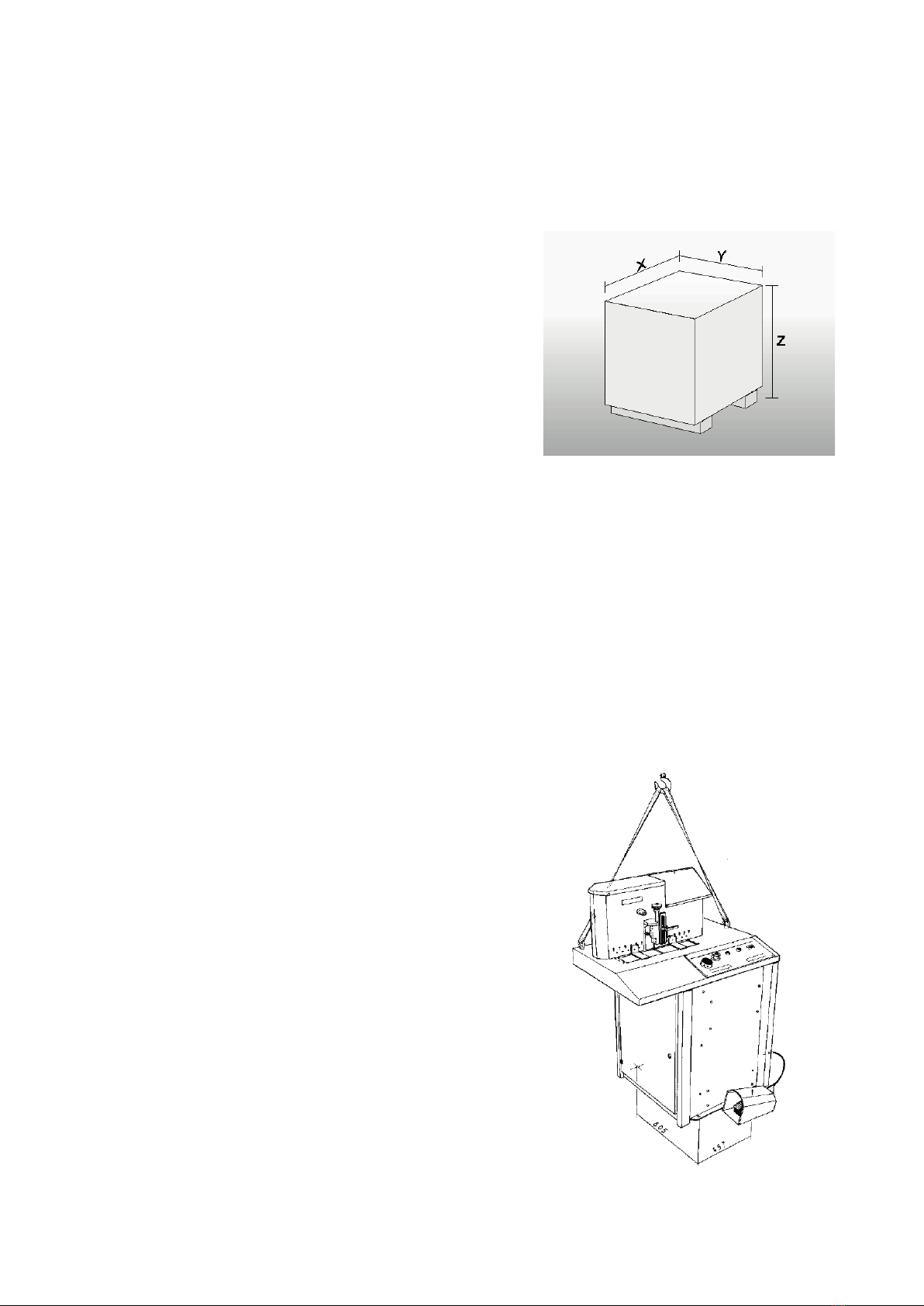
Size of package: x = 97, y = 107, z = 178 cm.
Storage
The manufacturer has protected the machine against corrosion by using the Zerust method. The machined
parts have been treated with Perigol 100 protective agent. A Zerust vapor capsule has been put into the
electric box, and the machine has been packed into a bag made of Zerust film.
The protection is effective for months if the package is not opened. After opening it, the protection of the
wrapping film ceases. If the machine is not yet brought into use, it must be reprotected against corrosion. The
machine is to be stored in dry indoor conditions. Storage temperature above 0°C.
Remove the protective agent according to the instructions enclosed in the package.
Mounting
The adjacent picture shows an appropriate way to lift
the machine after it has been unpacked.
Mount the machine on an even floor level, which is
steady enough to carry the weight of the machine,
approx. 300 kg.
It is recommended to screw the machine on the floor
with four M12 wedge anchors. Boreholes in the floor: Ø
12 mm, depth 55 mm.

6
HELP PROTECT OUR ENVIRONMENT
Disposal of the packing material
The transport and protective packing is mostly manufactured from the recycled or recyclable materials.
Please check local environmental regulations before disposing of packing materials. Rather than throwing
these materials away, please take them to your community recycling centre.
Disposal of your old machine
Old machines contain materials which can be recycled. Please contact your recycling centre of scrab
merchant before discarding the appliance.
Handle the waste oil and filters according to law.
WARNINGS
GENERAL
The machine is intended for professional use. It is to be operated only by a trained operator who has
understood the dangers involved in the operation.
The machine has been designed for cutting hydraulic hoses only.
Never touch the blade or keep your hand too close to the cutting point!
The rotating cutter blade is guarded by guard plates mounted on the cutting point. When the pusher is in up
position, the springing guard plates on both sides of the blade are in horizontal position and cannot drop down
and let the blade come into view. When a hose is being cut, the plates drop down, thus enabling cutting.
When a hose is being cut, it pushes the guard plates forwards and the blade comes into view. After cutting
the hose the guard plates return automatically to protect the blade.
Check that the blade rotates to the correct direction. Wrong direction of rotation detaches the blade.
The blade remains to rotate approximately 60 sec after switching off the current. Prior to any maintenance
operations, follow the safety time (60 sec) after switching off.
The sound pressure level rises up to 82 dB during the cutting. It is recommended to use hearing protectors.
Use only original Finn-Power cutting blades!
Cuttings inside the blade cover housing might cause a fire risk! Clean the blade cover
housing often enough. After operation make sure that there is no smoky cuttings inside the housing.
Make sure that your working area is lighted and clean enough.
Failure to use appropriate safety glasses and -gloves, and failure to follow the operating-and safety
instructions can result in serious injury.
7
WARNINGS
General
The machine is intended for professional use. It is to be operated only by a trained operator who has
understood the dangers involved in the operation.
The rotating cutter blade is guarded by guard plates mounted on the cutting point. In neutral position when
the foot pedal is not pressed, touching the blade has been prevented so that the pusher for making the cutting
movement is in the upper position, thus prohibiting the guard plates from dropping down.
When a hose is being cut, it pushes the guard plates downwards and then blade comes into view.
Do neither touch the blade nor keep your hand too close to the cutting point!
The sound pressure level rises up to 82 dB during cutting. We recommend that you use hearing protectors.
LABEL DEFINITION
General Warning label. There are items that
require attention.
WARNING 1 WARNING: DANGER OFSQUEEZE
Do not put your hands to the cutting point while
the motor is running!
Cutting and crimping hazard between the
pusher and the blade.
WARNING 2
Keep the door closed while the motor is
running or blade rotating! After stopping, the
blade rotates for approx 60 s.
WARNING 3
USE SAFETY GLOVES WHEN YOU HANDLE
THE BLADE!

8
WARNING 4
WATCH OUTFOR THE ROTATING MOTOR
AND BLADE!
WARNING 5
High voltage!
The electric box is to be opened only by a
professional electrician!
WATCH OUT FOR THE SPARKING AND
FLYING ITEMS!
Danger zones

8
WARNING 4
WATCH OUTFOR THE ROTATING MOTOR
AND BLADE!
WARNING 5
High voltage!
The electric box is to be opened only by a
professional electrician!
WATCH OUT FOR THE SPARKING AND
FLYING ITEMS!
Danger zones
9
COMMISSIONING
Electrical connection
CAUTION! Check that the machine voltage (see type plate) is equal to your supply voltage. For proper
installation to local code, consult a licensed contractor.
Tighten the cable clamp.
Connect the phase conductors to the respective L1, L2 and L3 terminals in the junction box. Connect the
earth connection to the ground terminal. Check the connection against the wiring diagram enclosed in the
spare parts list of your cutting machine.
Check that the motor rotation is parallel with the arrow on the cover plate. In case the motor rotates in wrong
direction, two phase conductors in the junction box must be interchanged.
Compressed air connection
It is recommended to use the air dryer for cleaning and drying the compressed air. The compressed air dryer
protects the machine from dust and water.
Connect the compressed air supply to the bayonet coupling behind the machine. The minimum pressure of
compressed air is 5 bar. When the cutter is stopped, the valve closes up and the pipe system of the machine
is emptied of compressed air.

10
OPERATION
Control identification
1. Supply disconnecting device separates the machine from power supply. However the device itself
can be made dead only by disconnecting the plug or supply cable from the mains.
1.1. Push-buttons for starting and stopping the motor.
1.2. Emergency stop button for turning off the current immediately and emptying the
compressed air system.
1.3. Counter records the up-and-down motion of the pusher in the digital display. The display is
reset to zero by pressing the RST push-button. (RST=Reset).
2. Adjusting shaft for adjusting the pusher height according to the hose diameter.
3. Adjusting screw for controlling the cutting speed according to the hose diameter and the quantity
of wires per hose (eg 2-wire, 4-wire).
4. Pneumatic pusher for pushing the hose to be cut against the blade.
5. Foot pedal makes the pusher move up and down. The cutting movement is generated by an
oilstabilized pneumatic cylinder. The pusher moves down as long as the foot pedal is pressed. After
releasing the foot pedal, the pusher rises up.
6. Connection for fume extractor (Option)
7. Shut-off valve of compressed air inside the machine
8. Bayonet coupling for compressed air supply
9. Paper tray
Operating area of the cutter is in front of the machine where the foot pedal is used.
Fume removal
It is recommended to install a hose and a fume extractor in the connection (6) behind the machine for leading
out the cutting fume.
11
Control identification R2
(OPTION)
1. Supply disconnecting device separates the machine from power supply. However the device itself can
be made dead only by disconnecting the plug or supply cable from the mains.
1.1. Push-buttons for starting and stopping the motor.
1.2. Emergency stop button for turning off the current immediately and emptying the compressed air
system.
1.3. Counter records the up-and-down motion of the pusher in the digital display. The display is reset to
zero by pressing the RST push-button. (RST=Reset).
2. Adjusting shaft for adjusting the pusher height according to the hose diameter.
3. Adjusting screw for controlling the cutting speed according to the hose diameter and the quantity of
wires per hose (eg 2-wire, 4-wire).
4. Pneumatic pusher for pushing the hose to be cut against the blade.
5. Two-handed Push-buttons makes the pusher move up and down. The cutting movement is generated
by an oilstabilized pneumatic cylinder. The pusher moves down as long as the push-buttons are pressed.
After releasing the push-buttons, the pusher rises up.
6. Connection for fume extractor (Option)
7. Shut-off valve of compressed air inside the machine
8. Bayonet coupling for compressed air supply
9. Paper tray
10. Safeguards with two-handed buttons for protecting hands during hose cutting.
Operating area of the cutter is in front of the machine where the foot pedal is used.

12
Covers
PLATES
When the pusher is in upper position, the springing guard plates on both sides of the blade are in horizontal
position and cannot drop down and let the blade come into view. When a hose is being cut, the plates drop
down, thus enabling cutting.
FRONT COVER
The front cover attached to the pusher protects the operator from the blade during cutting. It must be in the
lower position.
CRIMPING COVER
The crimping cover is also attached to the pusher. It prevents your hands from getting between the pusher
and the stop plate above it.
DOORS
The doors protect the blade and the power transmission equipment.
THE COVERS MUST BE IN THEIR PLACES AND THE DOORS CLOSED DURING CUTTING !
Test run
•Start the motor.
•Examine the direction of blade rotation. The blade has to rotate away from the operator, not towards him.
•Check the operation of the foot pedal and the pusher. The pusher is to move downwards when the foot
pedal is pressed. After releasing the foot pedal, the pusher is to rise to the upper position.
13
Hose cutting
DO NOT KEEP YOUR HANDS TOO
CLOSE TO THE CUTTING POINT!
USE EYE SHIELDS!
•Place the hose to the cutting point as indicated
in the figure (1).
•Use the adjusting shaft (2) to adjust the pusher
height so that the free motion of the pusher
remains minimal: lower for small hoses and
upper for large ones.
•To prevent overheating of the blade, use a low
enough cutting speed. Overheating may cause
crazing in the blade, and pieces may thus
loosen from it during cutting.
•Adjust the cutting speed with the adjusting
screw (3) using the lower speed the larger the
hose is and the more wires in it.
•With the adjusting screw turned clockwise to
the bottom, the pusher does not move when the
foot pedal is pressed.
•When the adjusting screw is turned counter-
clockwise, numbers of turns can be seen and
selected:
1-2 turns
for 1” to 2” diameter multiwire hoses
2-4 turns
for ¾” diameter multiwire hoses
4-7 turns
for ¼” to ½” diameter 2-wire hoses
•Press the foot pedal, and the hose is being cut.
•Release the foot pedal and remove the hose.
R2 OPTION
•put your hands through safeguards, see chapter Control identification R2, and press both buttons of
two-handed control while keeping hose and the hose is being cut
•Release the push-buttons and remove the hose.
NOTE! two-handed push-button must be pressed at the same time.
If the machine does not work...
•Check that the plug is in the socket.
•Make sure the supply disconnecting device is in position 1.
•Check that the emergency stop button is released.
•If still not working, contact a serviceman.
MAINTENANCE
The following maintenance operations can only be performed by a qualified specialist.
PRIOR TO ANY SERVICING OPERATION, TURN THE SUPPLY DISCONNECTING DEVICE TO
POSITION '0' AND LOCK THE DEVICE.

14
Tightening of V belts
•Open the door on the right.
•Loosen the two M12 locking screws on the
motor base plate (7) (see picture, page 7).
•Loosen the locking nut from the clamping
screw (2). Turn the screw clockwise, and
the belts tighten. The tightness of original
belts is 11.7.-17.2 Nm.
•Tighten must be elastic about 5-8mm.
•Tighten the locking nut and the locking
screws of motor base plate.
Blade change
•Use safety gloves when you handle the
blade.
•Open the door on the left.
•Drop the blade approx 10 mm (see chapter
blade sharpening and adjustment).
•Unscrew the clamping screw (8) in the
middle of the blade and replace the blade
(9).
•Adjust the blade according to the instruction.
•Close the door and lock it.
Blade adjustment
The height of the blade is adjusted as follows:
•Disconnect the machine from the mains.
•Open the right side door.
•Loosen the locking nuts (3) and (1) (see
picture, page 8).
•Turn the screw (5) counter-clockwise and
adjust the blade 2 -5 mm below the
springing guard plates.
•Tighten the locking nuts.
Oil
There is mineral oil for speed adjustment in the
cutting cylinder. There is no need to replace the
oil.
Cleaning
Clean the blade housing of rubber dust and
empty the scrab bins under the blade when
required.
CM-blade.eps

15
GUARANTEE
The machines produced by Lillbacka Powerco Oy are guaranteed against defects in material and
manufacture. Within the limits of the guarantee, the defective part will be replaced with a new one, or when
possible, repaired free of charge
The guarantee is valid for 12 months after commissioning, yet for a period not exceeding 18 months after
delivery ex works Alahärmä, Finland.
The guarantee does not compensate for damage due to improper use, overload, neglect, or normal wear.
Working and travelling costs as well as freight charges caused by guarantee repairs are not covered by the
guarantee.
Guarantee repairs shall be carried out at Lillbacka Powerco Oy, Alahärmä, Finland, or by an authorized Finn-
Power service. In case guarantee repair is demanded, the customer has to prove that the machine is under
guarantee.
LILLBACKA POWERCO OY DO NOT WARRANT FOR ANY INCIDENTAL OR CONSEQUENTIAL
DAMAGES, OR FOR ANY OTHER LOSS, DAMAGE OR EXPENSE OF ANY KIND, INCLUDING LOSS OF
PROFITS.
TECHNICAL DATA OF CM75 FUME EXTRACTOR
Voltage 220 V
Free air capacity 0.14 m3/S (500 m3/h)
Nominal power 170 W
Electric connection straight to the socket in the cutter
Operation simultaneous with the cutter
Protection class IP 54
Size of connecting duct Ø 103 mm
Recommended sizes for exhaust ducts shorter than 2 mm Ø 125 mm
2…5 m Ø 160 mm
longer than 5 m Ø 200 mm

16
Technical data
CM75 PH
Capacity 2”
Electric motor 7.5 kW
Cutter blade Ø 520 x 4 mm, centre hole Ø 38 mm
Speed of blade rotation 2840 rpm
Sound pressure level 82 dB(A) during hose cutting,
74.9 dB(A) idle speed
Frequency 50 Hz
Motor power kW 7.5
Voltage V / Current A / Fuse A 230 / 15.2 / 35
400 / 8.5 / 25
/ /
Frequency 60 Hz
Motor power kW 9
Voltage V / Current A / Fuse A 230 / 15.5 / 35
400 / 8.6 / 25
/ /
Overall dimensions:
Weight 220 kg, without oil.
READ THE FOLLOWING INSTRUCTIONS THOROUGHLY TO SECURE
SAFE AND CORRECT OPERATION OF THE MACHINE.


Table of contents
Other Lillbacka Powerco Industrial Equipment manuals
Popular Industrial Equipment manuals by other brands

ABB
ABB HT603383 Operation manual

FRIEDHELM LOH
FRIEDHELM LOH Rittal TopTherm SK 3126.1 Series Assembly instructions

Rohloff
Rohloff SPEEDHUB 500/14 Mounting

Spirax Sarco
Spirax Sarco UTD30 Series Installation and maintenance instructions

Balluff
Balluff BCS Q40BBAA-PIM20C-EP-GS04 Series user guide

Belle Group
Belle Group PCX 12/36 Operator's manual