4
CONTENTS
CONTENTS........................................................................................................................... 4
GENERAL ............................................................................................................................. 5
TRANSPORT .......................................................................................................................................5
STORAGE............................................................................................................................................5
MOUNTING..........................................................................................................................................5
HELP PROTECT OUR ENVIRONMENT ............................................................................... 6
DISPOSAL OF THE PACKING MATERIAL ........................................................................................6
DISPOSAL OF YOUR OLD MACHINE................................................................................................6
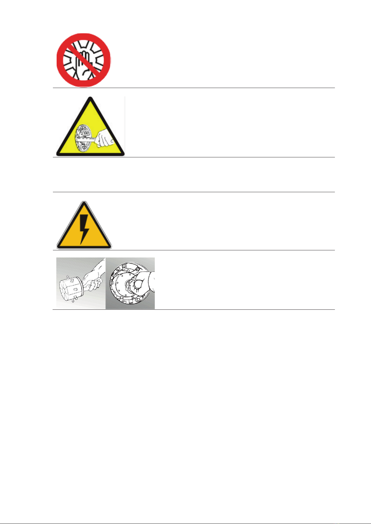
WARNINGS........................................................................................................................... 6
GENERAL ............................................................................................................................................6
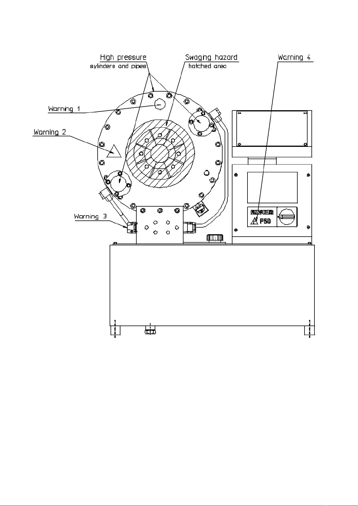
DANGER ZONES ................................................................................................................................8
COMMISSIONING................................................................................................................. 9
OIL FILL ...............................................................................................................................................9
ELECTRICAL CONNECTION..............................................................................................................9
RUNNING IN........................................................................................................................................9
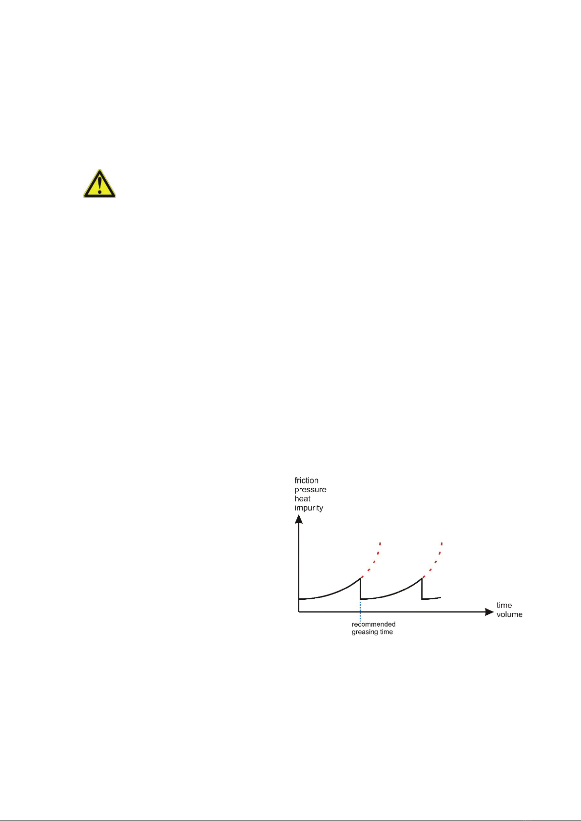
GREASING .......................................................... VIRHE. KIRJANMERKKIÄ EI OLE MÄÄRITETTY.
QUICK FIX-PACKAGE.........................................................................................................................9
OPERATION ....................................................................................................................... 10
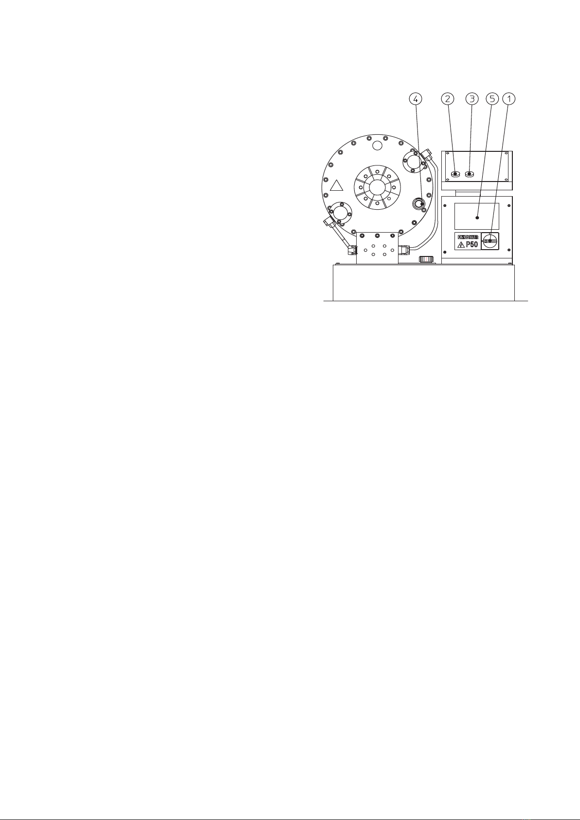
CONTROL IDENTIFICATION............................................................................................................10
TEST RUN .........................................................................................................................................10
SELECTING THE DIE SET...............................................................................................................11
FP140 DIE SETS ......................................................................................................................................... 11
INSTALLING THE DIE SET ...............................................................................................................12
QUICK CHANGE.......................................................................................................................................... 12
CHANGE OF A SINGLE DIE........................................................................................................................ 12
SETTING THE CRIMPING DIAMETER.............................................................................................13
FINAL DECELERATION....................................................................................................................13
OPERATION LIMITATIONS..............................................................................................................13
CRIMPING........................................................................................................................... 14
IF THE MACHINE DOES NOT WORK…............................................................................. 15
PREVENTIVE MAINTENANCE........................................................................................... 16
CLEANING.........................................................................................................................................16
GREASING ........................................................................................................................................16
OIL CHANGE .....................................................................................................................................17
FILTER CHANGE ..............................................................................................................................17
MASTER DIE SPRING CHANGE......................................................................................................17
PRESSURE PIPES............................................................................................................................17
RE-CALIBRATION OF CRIMPING DIAMETER DIAL .......................................................................18
GUARANTEE ...................................................................................................................... 18
TECHNICAL DATA ............................................................................................................. 19
TECHNICAL DATA P51...................................................................................................................19
TECHNICAL DATA P60...................................................................................................................20
GENERAL
Finn-Power crimping machines are electrically operated hydraulic crimping machines for hydraulic hose
assemblies.
The crimping machine comprises a crimping head and a hydraulic unit mounted on the oil tank which
serves as machine frame.
Finn-Power crimping machine is normally delivered with a 3-phase electric motor. On request it can be
equipped with a single phase motor.
TRANSPORT
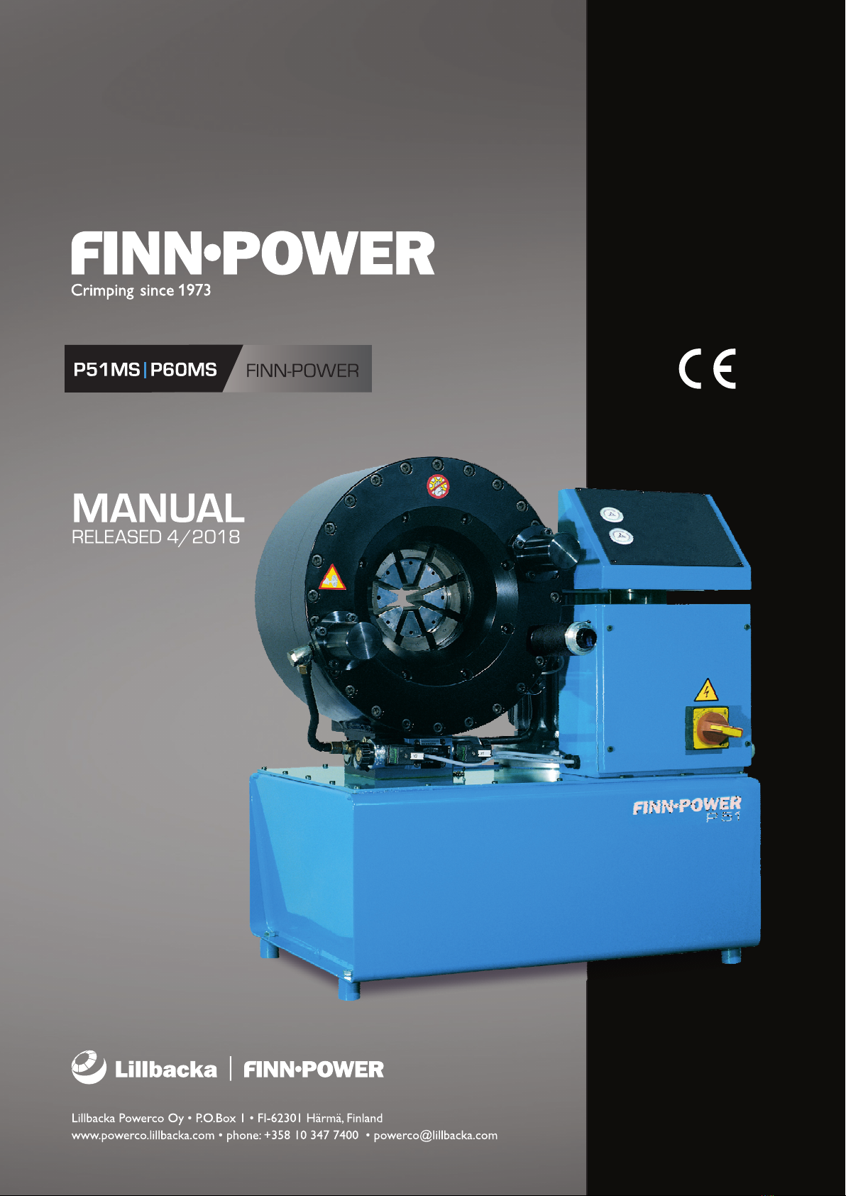
The packed machine is transported on a pallet, which is
easy to move and lift by a fork-lift truck. After unpacking,
the machine can be lifted using a hoisting belt.
Size of package: x = 82, y = 102, z = 113 cm.
STORAGE
The manufacturer has protected the machine against corrosion by using the Zerust method. The
machined parts have been treated withPerigol 100 protective agent.
A Zerust vapor capsule has been put into the electric box, and the machine has been packed into a bag
made of Zerust film.
The protection is effective for months if the package is not opened. After opening it, the protection of the
wrapping film ceases. If the machine is not yet brought into use, it must be reprotected against corrosion.
The machine is to be stored in dry indoor conditions. Storage temperature above 0°C.
Remove the protective agent according to the instructions enclosed in the package.
MOUNTING
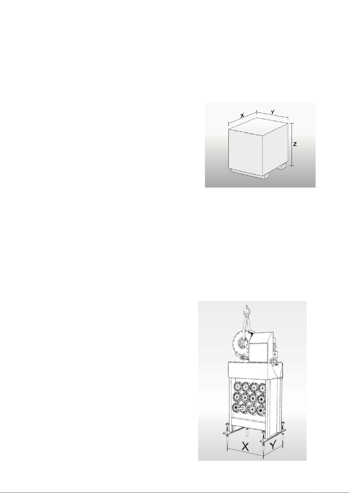
The adjacent picture shows an appropriate way to lift
the machine after it has been unpacked.
It is recommended to mount the machine on a Finn-
Power table. Before mounting, the table must be
screwed on the floor with four M12 wedge anchors.
Boreholes in the floor: Ø 12 mm, depth 55 mm.
When the machine is mounted on a Finn-Power table,
the four shoes under the machine are removed.
The table with assembly instructions is packed
separately.
The crimper may be installed on some other table as
well, provided it is sturdy and broad enough or it has
been fastened on the floor so that it cannot fall over.
Furthermore, there must be a hole in the table to
enable emptying the oil tank through the drain plug.
x = 625 mm, y = 560 mm.