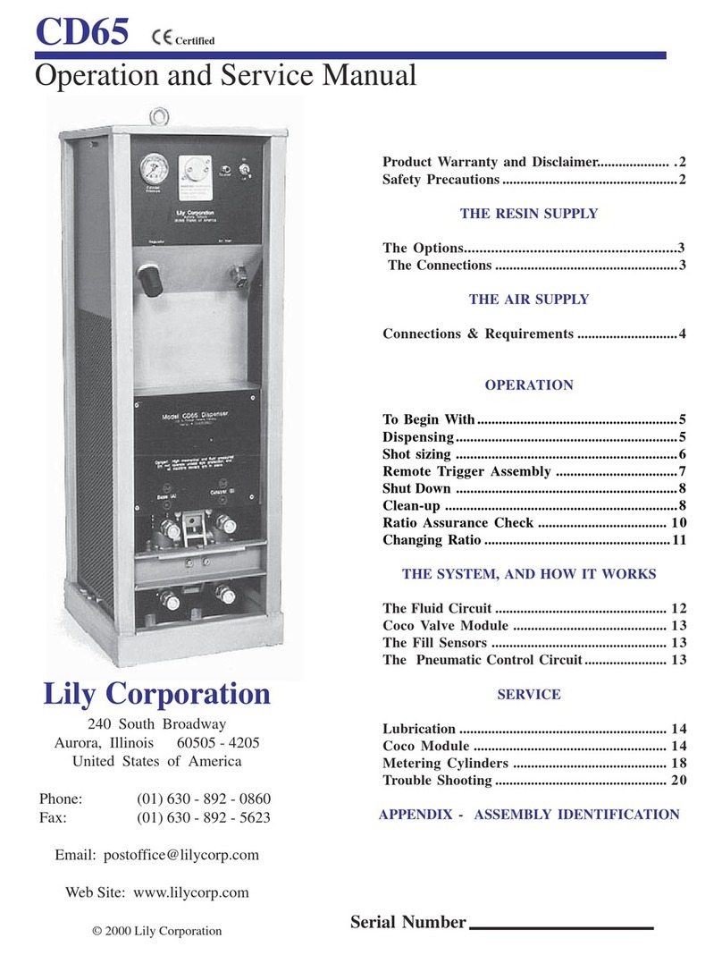
Lily Corporation CD15 Operation manual

1 Ver. 1.6
Product Warranty and Disclaimer 2
Safety Precautions 2
The Resin Supply
Fluid Connections 3
Filling The Supply Tanks 3
Monitoring The Resin Supply 4
Operation
The System and How It Works
Servicing the System
To Begin With 6
Dispensing 6
Shut Down 7-8
Clean - Up 7
Ratio Assurance Check 8-9
Changing Ratio 10
The Fluid Circuit 11
The Fill Sensors 12
Lily Corporation
240 S. Broadway
Aurora, Illinois 60505-4205
United States of America
Ph: 630-892-0860
Fax:630-892-5623
www.lilycorp.com
Operation and Service Manual
CD15
The Air Supply
Connections & Requirements 5
Troubleshooting
Troubleshooting 40-41
Parts Diagrams 24-39
Parts Diagrams
Lubrication 12
COCO Module 13
Disassembly 13-14
Assembly 15-17
Metering Cylinders 17-18
The Control Circuit

2 Ver. 1.6
EXPRESS WARRANTY AND DISCLAIMER OF IMPLIED WARRANTIES
Lily Corporation unconditionally guarantees its products to be free of defects in material or
workmanship and further warrants that, for a period of three months from date of factory
shipment, its products will meet the performance criteria stated in Lily Corporation’s
publications.
There are no other warranties, expressed or implied, including those of merchantability and
fitness for particular purposes.
Lily Corporation cautions the users of its products that epoxies must be
metered at the correct ratio and thoroughly mixed to achieve their formulated
strength. The user is further cautioned that thorough mixing within a static
mixing device can only occur with uniform flow of the two components.
Transmission of the two components through separate hoses to a remote
mixer may result in uneven flow of the components due to swelling and
contracting of the hoses, or different compressibility of the material
Warning and Safety Precautions
The CD15 can develop fluid pressures in excess of 1000 pounds per square
inch. Everyone within 25 feet should wear eye protection when the system is
energized. Mechanical members are actuated under forces of up to 500 psi.
Maiming injuries can be incurred. Do not energize the system unless all
screens are in place, and fingers, tools, and other objects are outside of the
frame of the machine.
Become thoroughly acquainted with first-aid procedures recommended by your
resin supplier in the event resin enters one’s eyes. If solvents are to be used
for cleaning, personnel should become thoroughly acquainted with their
characteristics. Most solvents are hazardous under all circumstances and
extremely dangerous in non-ventilated areas, or at elevated temperatures.
A thorough understanding of the Operator’s Manual is crucial to the safe
operation of the CD15. Do not attempt to operate this system until thoroughly
familiar with it’s contents. Phone Lily Corporation if clarifications are needed.

3 Ver. 1.6
Resin Supply
Fluid Connections
Use a 7/8” wrench to remove the caps and connect the
hoses. Some fluid may drip from the fittings . It is a
harmless material used to test the equipment following
manufacture, and does not need to be purged from the
system before dispensing. Stow the caps on the
magnetic flange of the channel.
Leave the inlet fluid fittings connected. Their
disconnection and re-connection only leaves
opportunities for costly error.
AB
Connect the fluid hose from the A tank (base resin) at the
lower left hand fitting (base resin inlet) on the front of the
CD15 dispenser. Connect the B tank (catalyst) at the
lower right hand fitting (catalyst inlet) as you view the
dispenser.
Install the Tempest mixer at the dispenser outlet (upper) fittings by
mating and tightening the two ½” compression fittings. Tighten the
fittings uniformly or they will bind and be difficult to assemble. The
fittings can be drawn up with the fingers, and then snugged with a
7/8” wrench. Be certain the component designations ( A & B
marked on the mixer) and the dispenser outlets match.
Filling The Supply Tanks
Epoxies have two components: The base resin, (Part A) is nearly always the majority
component if the ratio is other than 1:1. The catalyst (Part B) (“B” does not stand for base!)
is also known as the hardener. The catalyst is usually thinner than the base. It is of the greatest
importance that the person placing the components into the reservoirs knows—without any
doubt—the difference. If there is any doubt as to which is which, STOP!......until you “know”
1. Rotate the selector valve
pointer 180° from the air inlet
tubing. This will close off
incoming air, and vent the tank.
2. Lift the bale and press
down on the tank lid to free it.
3. Twist and tilt the lid until it
clears the opening. The lid
seal should be attached to the
rim. If not, check to see if it has
dropped into the tank, or stuck
to the underside of the tank lip.
4. After the material has been
added, replace the lid. Lock it
into place by pushing its bale
forward. Rotate the selector
valve pointer back toward the
air supply tubing to energize
the tank.

4 Ver. 1.6
Resin Supply
Warning: Corrosive damage to system components can occur if a resin component has a
PH of greater than 10 or less than 1.
Monitoring The Resin Supply
If either resin container is depleted, the CD15 will dispense the remaining component. Air is a
fluid, and the system cannot tell the difference. In the case of crack injection, the result may
be very costly, as it is unlikely that the error can be fully corrected. Therefore,
Do not allow the supply tanks to run out of material
When the dispenser is supplied by pressure vessels, it is not possible to
see how much resin remains in the tanks. However, the resin supply can
be monitored by using the counter on the control panel. The counter
registers the number of cycles the dispenser makes.
Resin
Ratio
Cycles
Per
Gallon
1:1 40
2:1 54
3:1 61
3.5:1 63
4:1 65
To use the counter to monitor resin consumption, go to the chart to
determine how many cycles occur in dispensing a single gallon of
combined components at the ratio you are using. For examples, if you
are dispensing at a 2:1 ratio, one gallon of material (the combined
components) will be consumed with every 54 cycles. If you are
dispensing at a 3.5:1 ratio, one gallon of material will be consumed
with every 63 cycles.
Next, decide how many gallons can be
safely dispensed without depleting either
component. If, for example, the ratio is 2:1,
and you have placed 4 gallons in the base
tank and 2 gallons in the catalyst tank for a
total of six gallons, 4 gallons of the
combined components can be safely
consumed. This will leave a reserve of two
gallons.
Now set the counter to zero by depressing the bar beneath the window. Mark the number 216 (4
gallons of resin @ 54 cycles per gallon = 216 cycles) in numbers on the top of the machine. Use a a
Magic Marker or other conspicuous method to remind you to pay attention to the gauge reading.
Until the count approaches 216, you do not have to worry about the supply.
It is recommended that a minimum of 2 gallons be reserved as a margin. This is especially important
at ratios other than 1:1. For instance, if the ratio is 4:1, a two gallon reserve leaves less than one half
gallon in the catalyst tank! If you are using a ratio that is not listed on the chart, ask Lily Technical
Service for the number of dispense cycles at the ratio you are using.

5 Ver. 1.6
The Air Supply
The air connections are the ‘press to connect’ variety. The connection
is made by firmly inserting the tube end into the fitting. It is released by
pulling the fitting collar firmly back against the fitting body while pulling
the tube from the fitting.
An excess of tubing is provided with
this assembly. Trim the assembly to fit
your installation.
Connections & Requirements
S-161
S-654

6 Ver. 1.6
The Air Supply - HT15 Mounted
The air connections are the ‘press to connect’ variety. The connection
is made by firmly inserting the tube end into the fitting. It is released by
pulling the fitting collar firmly back against the fitting body while pulling
the tube from the fitting.
An excess of tubing is provided with
this assembly. Trim the assembly to fit
your installation.
Connections & Requirements
Air Compressor
Connection
Bulkhead Connection at
Handtruck
Connection to CD15
Air Lines to Pressure
Vessels

7 Ver. 1.6
Operation
●Purge the air hose from the compressor of water or other contaminants.
●Switch the dispenser cabinet off.
●Point the selector valve handles on the material tanks toward the tubing.
●Fix a mixer or manifold and fluid valve at the material outlet fittings.
●Reduce the dispenser air pressure to zero by turning the regulator counter
clockwise until its spring is relaxed.
●Make certain water for eye-wash is at hand, and that those nearby are wearing
goggles and protective gear as recommended by the resin supplier.
●Take steps I and II under Clean-up on Page 7.
To Begin With
Dispensing
Connect the air supply, and switch the air on. Increase the air pressure at the dispenser
regulator until the system begins to dispense. Slowly increase the pressure to the maximum
while observing for fluid or air leaks. This practice will identify any damaged tubing, seals, or
fittings before the system is moved on site. Following the high pressure check, reduce the
pressure to that selected for the application at hand. The dispense pressure may be altered
at any time by adjusting the regulator. Once the pressure setting has been selected, the unit
will continue to dispense at that pressure until the setting is changed. Note: The dispenser
pressure gauge will only register a reading during a dispense cycle.
A stem within a gage slot tracks the vertical travel of the dispense air
cylinder. This enables the operator to monitor the dispense rate of the
unit, and to determine when it has stalled due to the refusal of a crack
to accept additional resin.
The regulator at the control panel regulates the air pressure only to the
main air cylinder when on its dispense (downward) stroke. The
pressure it exerts on the metering pistons determines the pressure at
which the resin exits the dispenser. However, the air cylinder pressure
is never the same as that of the resin pressure. The resin pressure will
vary with the ratio for which the dispenser is set. The chart at the left
lists the relationship between the regulated cylinder pressure and the
resin pressure at various ratios.
Ratio Factor
1:1 4
2:1 5.4
2.5:1 5.7
3:1 6
3.5:1 6.2

8 Ver. 1.6
Operation
Shut Down
Because the resin components are not joined within the dispenser, no clean-up of the
dispenser is required. And, most epoxy resins can be left within a system indefinitely.
However, there is a very important step to be taken at shut-down if (a), a low viscosity resin
is being used, and (b), a mixer or manifold is fixed directly to the outlet fittings of the Coco
module. The procedure is called “burping”. Burping is necessary because the base and
catalyst components of most low viscosity resins have a much different specific gravity. Like
vinegar and oil in salad dressing, one is heavier than the other, and quickly sinks to the
bottom. Until they are mixed, the base component tends to sink beneath the catalyst. When
the components hover together within a mixer fixed to the outlet valves, it is possible within a
very few minutes for the base component to settle and pond out beneath the catalyst. With
sufficient time, it may enter the catalyst outlet valve with costly results as it hardens
overnight.
Clean Up
Use the Gusto Purge Assembly (Page #30) to clean the mixer, tubing, FF-2 valves, and other items
exposed to catalyzed resin. Complete steps 1 and 2 below to charge the Gusto tank before starting
injection. It is a precaution which allows clean-up in the event the air supply is lost due to compressor
failure. For with the Gusto tank fully charged with air, there is sufficient energy within the tank to
clean up at least the major components.
1. Vent the Gusto tank by rotating the selector valve so that it points away from
the adapter block, and towards the bronze filter. Remove the lid and pour about
one-half gallon of Acetone or Methyl Ethyl Ketone (MEK) solvent into the tank.
Do not use petroleum based solvents such as toluol, xylol, mineral spirits or
naptha, as they will destroy the Gusto lid seal. Do not fill the tank, as this will
reduce the volume of air available for an emergency clean-up.
2. Replace the lid and secure it with its bale. Rotate the selector valve 90
degrees so that it is closed to the inlet and outlet. Connect the air supply and
pressurize the tank at the maximum pressure available. Set the tank aside until
time to clean-up.
3. Next “burp” the CD15. To do this simply dispense a few ounces of material into
a waste container immediately after removing the mixer from the dispenser. This
will flush any base resin that may have entered the catalyst fitting or valve.
4. Immediately after burping the dispenser and disconnecting the mixer, cap the
dispenser outlet fittings with the caps secured at the magnetic bracket, Then
secure the mixer to the manifold at the Gusto tank. Disconnect the air supply from
the dispenser, and connect it at the Gusto air inlet. Close the FF-2 valve, and
then rotate the selector valve to point to the mixer.

9 Ver. 1.6
Operation
5. Allow the pressure in the volume tank on the compressor to catch up before introducing
the solvent bursts. With the maximum pressure and volume available, open the fluid outlet
valve. Quickly shake the Gusto tank to splash small solvent bursts into the air stream. Space
the bursts about 5 seconds apart. If a low viscosity resin is being used, 5 or 6 bursts are
usually sufficient to clean the mixer and tubing. However, if a thick material must be purged,
more bursts will be required. Keep the bursts as small as possible, for large dosages of
solvent choke the air stream velocity, reducing the scouring effect. Continue until the
exhausted solvent is free of resin.
6. To clean the interior of the FF-2 valves, lay the Gusto tank on its side so
that solvent floods the outlet fitting. Then, quickly rotate the valves a few
times under the full solvent flow.
Clean Up
Ratio Assurance Test
WARNING!The CD15 contains moving parts which are by definition wearing parts. Critical
components are wearing from the moment you energize the system. It is absolutely essential
that this wear be anticipated and monitored to assure proper ratio dispensing. Key personnel
must become familiar with the following procedure for monitoring the wear of metering seals,
for if it does not become routine, improperly metered material will result.
The frequency with which the performance of the seals should be checked varies with the
abrasiveness of the fillers within the product being dispensed, as well as the volume of resin
dispensed. Normally, once each week of operation is sufficient to detect any ratio error
before it becomes significant. However, if the results are critical, monitoring should be more
intense. The ratio check is a three stage procedure.
Stage I: To determine if the outlet valve seals are leaking in the direction of normal flow.
1. Switch the dispenser “off”. [This will open the inlet valves, and close the outlet valves.]
2. Remove the mixer from the dispenser.
3. Wipe the outlet fittings, and place a paper towel beneath them.
4. Wait at least five minutes, and then observe the towel for any evidence of leakage from
the fittings. If no seepage has occurred, move to stage II.
If seepage, regardless of how minute, has occurred, replace the leaking seals. If seepage,
regardless of how minute, has occurred, replace the leaking seals.

10 Ver. 1.6
Stage II: To determine if the Coco inlet valve seals are leaking in the direction of normal
flow.
1. Turn the pressure regulator counterclockwise until no pressure is registered on the gauge.
2. Flip the dispenser switch “on”. [This will open the outlet valves and close the inlet valves.]
3. Repeat steps 4 and 5 from Stage I.
If seepage, regardless of how minute, has occurred, replace the leaking seals.
Stage III: To determine if the Coco inlet valves are leaking in the direction opposite normal
flow.
1. Tightly cap the outlet fittings
2. Turn the switch “on”. [This will open the outlet valves and close the inlet valves.]
3. Rotate the directional valves to vent the pressure vessels.
4. Disconnect the material supply hoses at the dispenser.
5. Turn the dispenser pressure regulator knob clockwise to the maximum pressure available.
6. Wipe the inlet fittings, and place a paper towel beneath them.
7. Wait at least five minutes, and then observe the towel for any evidence of leakage from
the fittings.
If seepage occurs, regardless of how minute, has occurred, replace the leaking seals.
Ratio Assurance Test
Operation

11 Ver. 1.6
Operation
Changing Ratio
Ratio is determined by the relative diameters of the catalyst and base pistons. If the ratio is 1:1, both
metering pistons will be the same. However, with any other ratio, the catalyst metering piston will be
of a smaller diameter. Ratio is therefore changed by exchanging one catalyst metering assembly for
another. A metering assembly consists of a metering cylinder, a metering piston, and the seals, etc.
component to them. Metering assemblies for alternate ratios are available from Lily. A few simple
steps are required to change ratio:
1. Switch the dispenser off.
2. Use the directional valve to thoroughly vent the pressure vessels.
3. Remove the right hand and rear screens.
4. Grip the catalyst metering piston, and press it down until it is clear of the underside of the
main air cylinder end cap. The material in the metering cylinder will be forced to flow back into
the tank. If the piston does not go down easily, use a strap wrench to free it, and twist it as it
is pressed downward.
5. Use a strap wrench to turn the catalyst metering assembly
counter-clockwise until it is free. Do not attempt to remove the
assembly with any tool other than a strap wrench, as the chamber
may be damaged by any uneven grasping force.
6. Use the seal pick to remove the base manifold o-ring. Clean
the pocket thoroughly, and install a new o-ring in the lower
groove.
7. Lubricate the threads of the replacement metering asssembly with an anti-sieze
compound or silicone lubricant. Thread the assembly into the manifold by turning it clockwise
until it is seated. Do not overtighten. As the chamber bottoms out in the manifold you will
feel a definite stop. Do not tighten further.
8. Replace the screens.

12 Ver. 1.6
THE SYSTEM AND HOW IT WORKS
The Fluid Circuit
3
EE
A B A
F
DD
G
C
C
EE
DD
F
AB A
CC
G
The resin components are pressurized within vessels (A) or by pumps. Pressurized, the
components flow through open inlet valves (B) to enter their respective metering cylinders (C).
The metering pistons (D) are extended by the resin pressure until they bear against the main
air cylinder end cap (E).
After both metering pistons are fully extended, the inlet valves (B) close, and the outlet valves
(F) open.
The resin components then exit under the pressure exerted by the main air cylinder (E)
descending against the metering pistons (D).
The components merge at a mixer (G). When the dispense stroke is completed, the outlet
valves (F) close, the inlet valves (B) open to allow the metering cylinders to refill, as the main
air cylinder ascends.

13 Ver. 1.6
Sensors prevent the dispense cycle until both metering cylinders are completely filled. This is
important, because if a dispense cycle occurs before both metering cylinders are filled, there
will be a shortage of one component, and inadequate cure of the dispensed resin as a result.
The air signal that triggers the system to dispense is routed through a conduit within the main
air cylinder end cap. This conduit is intersected by two holes which vent, and thereby erase,
the signal if they are not plugged.
The holes can only be sealed off by the impingement
of the ends of both of the metering pistons when fully
extended. Once both of the vent holes are sealed,
(confirming the arrival of both pistons) pressure
builds in the air circuit to trigger the dispense cycle.
Urethane pads fixed to the ends of the metering
pistons cushion the impact against the air cylinder end cap, and make a tight seal at the vent
holes.
The Fill Sensors
THE SYSTEM AND HOW IT WORKS
If the air supply is properly maintained, the system will deliver literally millions of trouble-free
cycles. However, in the real world, that is not always possible.
Therefore, periodic (twice a year) lubrication of the air circuitry is
recommended. To do so, de-energize the system and remove the left
cover. Free the four way air fitting (P-189) from the elbow (P-242) fixed to
the air filter (S-570) by pressing the collar of the elbow down. Do not
disconnect any other tubing. Squeeze a generous dose of Lily Silicone
Lube (P-315) into the rigid leg of the four-way fitting. Reconnect the
fittings. No other lubrication is needed. Never use WD-40 or similar
products in the air circuit.
Lubrication
If the CD15 is properly maintained, service will involve little more than routine replacement of
dynamic seals exposed to material being dispensed. The frequency of seal replacement will
depend upon the material dispensed. Thousands of gallons of non-abrasive resin with good
lubricity may be dispensed with little, if any, service; while the use of an abrasive – and
usually inexpensive – material is likely to necessitate frequent seal replacement. Costly
damage to metering cylinders and their pistons may also result from the use of an abrasive
product.
SERVICING THE SYSTEM

14 Ver. 1.6
SERVICING THE SYSTEM
The COCO Module
When a ratio assurance check reveals a need for seal replacement at the Coco module, it is
not necessary to replace all of the seals within the module. Rather, replace only those seals
metering the same component. Resin components differ dramatically in terms of their
abrasiveness, so the wear of the seal managing one component is seldom an indication that
the seals on the opposite side are similarily worn.
It is good practice to replace the coupler shaft seals (S-328) when replacing the ball seals.
They are exposed to the same product, so the wear is comparable. Besides, the seals are
exposed during the course of replacing the ball seals, and therefore easily replaced in the
course of ball seal replacement.
When servicing the coco module, refer to the exploded parts view on page #26 as well as the
illustrated steps below.
Disassembly
Turn the switch off. Vent the fluid tanks, and disconnect the air supply to the dispenser.
Remove all three screens. Grasp the metering pistons and press them down into their
cylinders. This will purge the cylinders of material, which will flow back into the tanks.
Disconnect the material supply hoses at the Coco inlet fittings, and remove the mixer at the
outlet fittings. Then, follow the steps below:
1. Use a 13/16” wrench to
loosen the zero clearance
fittings at the rigid tube
segment (M-617).
Remove the tube, taking
care not to lose the seals
within the fittings.
3. Pull the assembly from
the frame. If is is not free,
use a plastic, wood, or
rubber instrument to urge
it loose.
2. Remove the bolt (S-334)
securing the spacer block to
the module frame (M-571).
4. Use an 8-15 mm snap ring
tool to remove the ring
retaining the coupler shaft (M-
581).

15 Ver. 1.6
SERVICING THE SYSTEM
Disassembly
5. Grasp the coupler
shaft (M-581) with a
cushioned tool, and
gently work it and its
bushing (M-802) from
the cavity.
7. Remove the O-Ring
(S-509) and the seal
spring (S-330) (concave
washer).
9. Use a seal pick to
remove the seal (S-
332). Take care not to
scratch the ball or the
wall of the pocket.
11. Use the seal pick to
gently urge the lower
seal from its seat. Take
care not to scratch the
housing.
6. Use a 3/16” allen
wrench to remove the
four screws securing the
valve to the spacer
block. If they do not
separate easily, tap
them apart. Use a
plastic mallet.
8. Remove the
remaining washer
(S-329).
10. Shake the ball
(M-803) free from the
valve body.
12. Remove the lower
washer and spring.
Take care not to scratch
the housing.
Cleaning Clean the components thoroughly, but do not use steel bristle brushes
or instruments likely to scratch or gouge. Most solvents and cleaning agents can
be used without damage to the stainless steel parts.
Inspection Carefully inspect each part. If possible, use a magnifier and light.
Pay special attention to the balls and the valve sockets. If there is any blemish,
replace the part. Flat and spring washers do not need to be replaced unless
damaged.

16 Ver. 1.6
SERVICING THE SYSTEM
1. Fit the seal spring
(S-330) into the pocket
with its concave side
toward the ball.
2. Place the washer (S-
329) over the spring.
Nudge it to be certain
that both it and the spring
are fully seated.
3. Insert the seal vertical
to the pocket until it is
within the pocket. Then,
twist it flat so that the
spring side of the seal is
facing down.
4. Nudge it into place
with the fingers, and then
press it firmly into the
bottom of the pocket with
the setting tool (M-806 )
from the seal kit.
5. Slide the ball into the
pocket with the detent
(slot) facing the coupler
pocket. Use the tang of
the coupler shaft (M-581)
to squarely align the ball
slot.
6. Install the exterior
seal (S-332) with the
spring groove facing
away from the ball.
7. Install the flat washer
over the seal, and apply
silicone lube to hold it in
place. Install the spring
with the concave side
facing the ball!!
9. Attach the valve
bodies to the Coco
Spacer Block (M-572).
Take care not to distort
the o ring seals. Snug,
but do not tighten the
bolts!
8. Press a new o-ring
into the groove around
the outside of the spring
and washer. Use
silicone lube to hold it in
place.
10. Insert the seal
(S-328) into the coupler
shaft bore. To avoid
damage to the seal
edges, start it
perpendicular to the
bore, and then flatten it
into place with the spring
toward the ball.
Assembly

17 Ver. 1.6
SERVICING THE SYSTEM
Assembly
11. Carefully insert the
coupler shaft (M-581),
bronze bushing (M-802)
and washer (P-469) into
the housing.
13. Make certain the
ring is fully engaged in
its groove.
12. Install the
retaining ring (P-505).
Note that one side of
the ring has slightly
rounded edges, while
the other side has a
sharp square edge.
The sharp edge of the
snap ring must face
away from the ball.
Use an 8-15mm snap
14. Before bolting the valve assembly to the frame, be certain that the
valve positions are oriented properly. If the Coco air cylinder rod (M-580) is
fully extended (normal position if the dispenser was switched off before
disassembly), the inlet valves (the bottom valves) should be open, and the
upper outlet valves closed. The valves are easily opened or closed by
grasping the coupler shaft (M-581) with a cushioned tool, and rotating it.
Slots are machined into the stems to indicate the valve positions. If the slot
is perpendicular to the flow the valve is closed. If the slot is in line with the
15. Fit the valve assembly to its frame. Make
certain that the valve spline fits snugly into the
frame slot. Apply an anti-seize compound to the
threads of the mounting bolt (S-334) and draw it up
16. Fit the Coco Alignment Gage (M-037) posts
into the inlet ports of the Coco Module. It may be
necessary to nudge the valve bodies with a
wooden or plastic tool to manage the fit. If the
valves don’t budge, slightly loosen the bolts (S-
310) securing the valve to the Spacer block.
Closed
Open

18 Ver. 1.6
SERVICING THE SYSTEM
17. With the gage posts fully inserted, snug the bolts securing the inlet
valve bodies to the center block. Then further tighten the bolts in
sequence, moving from corner to corner across the valve until all are
tight. Remove the Alignment Gage and move it to the outlet valves and
repeat the procedure. These steps assure smooth operation of the
valve sequencing cams and ease in removing and installing the mixer.
And finally, conduct a ratio assurance check!
The Metering Cylinders
1. Grasp the metering
piston and press it into
its cylinder, thus
purging the component
back into its tank.
3. Press the metering
piston from the cylinder
bore. If it is seized,
phone Lily or visit a
machine shop for
assistance. Do not
5. If the piston is
scratched or marred,
polish its surface with
an abrasive cloth until
no burr remains to
damage the metering
2. Loosen and
remove the metering
cylinder by rotating it
counter-clockwise. Do
not use a pipe wrench!
Use a strap wrench.
4. Clean the bore and
piston thoroughly.
Examine the cylinder.
If it is scratched or
otherwise damaged, it
must be replaced.
6. To replace the
piston seal, remove
the screw in the cap
retaining the seal.
Then remove the cap
and the seal.
The frequency of service will depend upon the abrasive content of the material being dispensed, and
to a lesser degree, the abrasive atmosphere common to many construction sites. The need for
metering assembly service is recognized by leakage between the metering piston and its cylinder,
sluggish extension of the piston, or by seisure of the piston within the cylinder.
To remove a metering cylinder for service, turn the dispenser switch off, disconnect the air supply at
the dispenser, rotate the selector valves on the material tanks to vent, remove the screens, and
follow the steps below:

19 Ver. 1.6
SERVICING THE SYSTEM
7.Replace the seal
with its spring groove
towards the bottom
of the piston.
9. If the piston cap is
larger than the piston
diameter, it, and its
cap, must be
removed to insert the
piston back into the
cylinder.
11. Use the seal pick
(P-457) to remove
the base manifold
o-ring seal. Clean
the pocket thoroughly
before installing a
new seal.
13. Replace the
screens.
8. Inspect the piston
pad. If it is torn or
worn, replace it by
removing its retaining
screw. Apply a drop
of blue Loctite thread
seal or equal to the
10. Lubricate the
piston and chamber
with silicone and
insert the piston pad
end first into the
bottom (threaded
end) of the metering
12. Apply an an anti-
seize compound to
the cylinder threads,
and then screw it into
the manifold. Do not
overtighten!
Following seal replacement, slight leakage may be noticed between the piston and the
cylinder. This will usually stop after dispensing a few gallons of resin.

20 Ver. 1.6
SERVICING THE SYSTEM
The Control Circuit
The CD15 is entirely pneumatic. It uses compressed air for its control circuit, as well as for energy to
dispense. An air circuit is nearly as reliable as an electric circuit if the air supply is clean, dry, and free
of lubricants and additives, other than those applied by the manufacturer.
To understand an air circuit, it is necessary to understand the symbols used:
The “Unregulated Air” symbol is used to indicate the presence of unregulated air. Rather than use
lines to show the tubing carrying unregulated air to energize various valves, the symbol avoids a
maze of lines more likely to confuse rather than enlighten.
The “Or” (P-794) element relays an air signal arriving from either inlet port. If a
signal arrives from one port “or” another, it is relayed.
The “Stroke Sensor” (P-182) sends an air signal from its port S whenever
there is no pressure in the line in which it is installed. However, if the line is
energized, port S is vented.
Table of contents
Other Lily Corporation Dispenser manuals
Popular Dispenser manuals by other brands

Dacor
Dacor Discovery DYWS4 quick start

Rocket Man
Rocket Man M1001 operating manual

Cornelius
Cornelius NITROPRO MINI instructions

Cornelius
Cornelius 2 Flavor Training manual

Schroeder America
Schroeder America 2V Dispenser 980 Installation instruction, parts list and configuration guide

TEFAL
TEFAL BR3019U manual