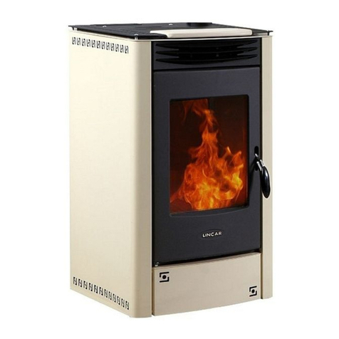
Lincar Stella 740 Guide

1/38
Stell
a
Mod. 740 – 740/SA
Siri
a
Mod. 840 - 840/SA
Residential space heatin g app liance with boiler f ired by wood pellets
USING– MAINTENANCE MANUAL
Equipmentsbuiltin conformity withEuropean Standardsfor the
markingand according to Art. 15a B-VG
Cod. 90003121 Rev. 1

mod. 740-740/SA–840-840/SA GB
2/38
Dear Customer,
Whil e we thank yo u for t he preferen ce you grant ed us, we rem ind y ou to read
carefully thepresent handbookbecauseit gives Youimportant warnings with
particular attention to the installation, utilization, maintenance and to the security of
the product in addition to condition of guarantee . To avoid it wi ll be considered “
IMPROPER USE” of the equipment and therefore“UNCORRECTLY
UTILIZATION” with possibly of decay of theguarantee.
INDEX
Section Pag.
Installation 3
Connection measurements 5
Security distances 6
Connections 7
Technical data 11
Utilization 12
Fuel 13
Controlpanel 14
Appliance regulation 15
St arting 16
In dications on Di sp l ay 17
Security 18
Controlpanel menu 19
Menu details 21
Routine maintenance 25
Extraordinary maintenance 26
Accessories 27
Possibile failures and cure 27
Alarmindications 28
Examples ofconnections 29
Technical data plate 36

mod. 740-740/SA–840-840/SA GB
3/38
INSTALLATION
SECTION DESTINATED TO THEINSTALLER
Prescriptions and norms
•Read carefu l ly the conten ts o f t h is hand book, it contain s imp ort ant in fo rmat ion and
instructions for installation, use, maintenance and product safety.
•The installation, the electrical as well as the hydraulic connection, the working
verification and the maintenance operations must be carried out by a qualified staffonly,
utilizing always theindividual security devices and all other security features foreseen by
local laws.
•The appliance must be installed inside an room considered suitable for installation and
use by competent authorities. All laws, standards and regulations in force on the
installation site must be observed, especially regarding fire prevention.
•Technological connection and appliance installation must be carried out by a qualified
staff, who is authorized to release a conformity certificate according with the normative
in force and current standards.
•All the normative concerning civil town planning and/or industrial in force must be
respected inside the installation roomof the appliance.
•All laws, standards and regulations in force on the installation site must be observed,
regarding: flues, electricity, water and steam, drains and wastedisposal,
•The appliance should be connected to an electrical plant suitable with the declared
electrical power ofthe appliance itself(see data plate).
•The manufacturer disclaims all responsibility caused by incorrect installation,
using, tampering, maintenanceor no respectof normative inforce.
•In order to avoid problems arising from residuals and/or deposit it is deeply
recommended to effect a complete washing of the plant (specially by new plants) before
connecting the appliance.
•Cut-off cocks must be installed out of the appliance, which permits to insulate the stove
in casethe thermal plant should be disconnected for maintenance and/or repair purposes.
•Flexible tubes are preferred to connect the appliance to the plant.
•Verify that the thermal plant is suitable with declared power ofthe appliance. The values
are reported on the technical data plate, which is placed on the appliance, a copy of it is
at tach ed in th is manual.
•The connection of the appliance to the thermal plant should also foresee a cock for the
emptying ofthe boiler. This cock should be placed on the backflow tube and, ifpossible,
connected to the a sink.
•The filling of the boiler and eventually of the
heating plant must be carried out by qualified
technicians, it is possible to control the pressure
of the boiler on the display, only after having
connected the appliance to the electric socket.
press button1to see the pressure.

mod. 740-740/SA–840-840/SA GB
4/38
Directions:
The appliance is equipped with a security valve, which (in case that for any reason the
pressure of the thermal plant is exceeding 3 bar) intervenes, discharging the fluid
contained into the boiler. In order to avoid annoying outlets of water (not due to
problems of the appliance) generated by overpressure of the hydraulic plant, we
recommend to install a pressure reducing valve regulated at 2 bar, placed before the
thermal plant charging cock.
The eventual intervention of the security valve brings forth outlets of water and/or
steam, which flows on the floor, therefore the plant should be prearranged so that the
valve intervenes effectively only for real necessity and not for other causes, such as
overpressures due to an incorrect plant.
In case of outlets of the thermal plantfluid, due to the intervention of the securityvalve,
LINCAR S.p.A. declines any responsibilityfor eventual damages to floors or what else
had comein contact with thefluid.
During the operating phase of the appliance, speciallyat reduced heating power (owing
to the high efficiencyof the heat exchanger) the combustion products, convoyed into the
chimney, mayreach temperatures which maycause condense.
In order to avoid scalingsand or other inconvenient due to condense, use well insulated
flues and condense collection systems, which are normallyavailableon the market. As
forseen bythe local standars.

mod. 740-740/SA–840-840/SA GB
5/38

mod. 740-740/SA–840-840/SA GB
6/38
MEASURESFUMEEXHAUSTANDWATER TUBESCONNECTIONS.
•Should it be necessary to make holes on the wall for the fumes exhaust, you have to:
−Measure and draw on the wall at natural size the points for the connection of the
stove;
−Realize the holes onthe wall;
−Connect the stove to the external chimney by mean of a tube for the fumes exhaust.
Couplingdimensions:
A– Plant delivery G 3/4 ” B– Sanitary water outlet G 1/2 ”
C– Water supplynet entry G 1/2 ” D– P lant backflow G 3/4 ”
E– Filling cock
Couplingdimensions :
A– Plant delivery G 3/4 ” D– P lant backflow G 3/4 ”
•In case of not horizontal connection of the fume exhaust tube but in vertical, keep a
security distance fromthe wall of100 mm.
740/SA STELL
A
840/SA SIRI
A
840 SIRI
A
740 STELL
A

mod. 740-740/SA–840-840/SA GB
7/38
Preliminaryoperations
•Take away the packing
•Before installation, check the appliance integrity. In case of doubt, do not use the
appliance and call the dealer.
•Packing materials is for recycle, getting it in thespecify container
Appliance positioning
•The installation roomshould have :
−A sui t ab l e fl oor fo r s to v e w eig ht . Sh ou ld the exis ti ng co ns t ru cti on not satis fy t hi s
req uiremen t , n eces s ary meas uremen ts must b e t ak en (I.e. a pl at e fo r th e di strib ut ion
ofthe weight)
−A suitable floor for stove calorific radiation, which grants against fire risks.
−The installation of the appliance should grant an easy access for the cleaning
operations ofthe appliance itself, as well as ofgas exhaust ducts and ofthe
chimney.
−A minimal distance from fla mmable materials (see security distances)
−The room must be continuously ventilated according to the local rules.
FLOOR PROTECTION
The equipment has to be put on a refractory surface.
In case of flammable floor ( moquette, parquet ..) it
is necessary to put a refractory base ( stainless steel,
ceramic etc ) with the following dimensions :
−Hold up in front ≥500 mm;
−Hold up lateral ≥300 mm;
−Hold up back ≥100 mm
SECURITYDISTANCES
•Fromnot flammable object :
A > 500 mm B > 100 mm C > 100 mm
•From flammable object and from principal wall
in reinforced concrete :
A > 1000 mm B > 200 mm C > 200 mm
•The minimal distance between the stove and
every flammable objects over it must be at least 1,5
mt
To measure fro m apparatus
external surface for every models

mod. 740-740/SA–840-840/SA GB
8/38
ELECTRICALCONNECTION
•The appliance is equipped with an electrical cable having an European plug. It is a type
“Y” connection and therefore any replacement of the cable must be carried out by a
qualified staff only. Feeding 1N 230V AC 50Hz. The electrical cable should be disposed
in such a way to avoid any contact with hot and sharp parts.
CONNECTION TO THE HEATING PLANT
•It’s advisable to read, follow and respect what indicated in the SectionInstallation.
•Do not use the appliance, if it has not been connected to a heating plant in working
co nditions .
•Before setting at work the appliance, it is necessary to fill the boiler and to eliminate
possible air bubbles.
•The appliance is equipped with a closed 8 liters expansion tank. The installer must
ABSOLUTELY verify the dimensions of the heating plant and, if necessary, replace the
expansion tank with another if the equipped one should not be sufficient.
•The appliance is produced with the internal working at closed expansion tank. In case the
appliance is used in pairing with other types of appliances or heating plants, the installer
sh ou ld p rearran g e al l po ssible exp ed i en ces to so lv e co mp at ibility prob l ems .
•Per. for the equipped appliances of fast sanitary water(mod. 740-840) is lively advised
the installation of a water softener (also according to the hardness of water system), to
avoid limestone coking in the rapid exchanger that in the long time reduce strongly the
efficiency and therefore the ability to produce warmwater
Connection to the chimney
•Before connecting the appliance, verofy if the technical data reported on the technical
correspond to the ones you have required at the moment ofpurchaser.
•All heating biomass equipments, especially wood and pellet stoves, have to evacuate the
combustion products in a flue, which must be built in conformity with normative in force
•The following instructionsdescribe„ informations for a good installation „ and they refer
to normatives in force, but they are not to be considered exhaustive for installations laws
CHIMNEYOR FLUE
•The chimney or flue should havethe following characteristics:
−Well sealed from combustion products, impermeable and completely insulated as
normative condictions
−The flue has to be built with materials well suitable for normal mechanical stress,
heat, action ofcombustion products and their condenses
−The flow has to be vertical with deflections no higherthat 45°
−A right distance from combustible or flammable material, insulated with an air
cav ity or righ t in su l at or

mod. 740-740/SA–840-840/SA GB
9/38
−Internal round section, the square or rectangular section should have round corner
with a ray notless than 20 mm
−Internal section should be constant, free and indipendent
−Rectangluar section with sides ration max of 1,5
−All manufacturer instruction should be respected concerning the section and the
building characteristic of the chimney or flue. For particular section, deviation of
section or path a complete inspection of exhaust fumes system will be necessary.
−It is ad vi s ab le that t h e fl u e should b e supplied wi th a „ chamb er „ fo r s ol id mat eri al
and condenses collection, placed under the flue throat and easy to be reached and
opened through a sealed „little door“ for inspection.
−In case of fire of chimney or flue, employ the right system to soffocate the flames
and call for firemen.
EQUIPMENTCONNECTION TOFLUEANDEVACUATION OFCOMBUSTION
PRODUCTS
•The flue should receive the exhaust fumes fro m one only heating equipment
•It is possible to realise an equipment composed by a fireplace and a cooking oven with a
sole exhaust fumes point towards the chimney, for which the manufactures has to
provide thebuilding characteristics ofthe duct ofthe exhaust fumes channel
•It is prohibited to connect in the same flue, a heating equipment and a suction hood
•It is prohibited to connect the exhaust pipe towards closed space even if it is in open air
•The direct exhaust fumes has to be done ahead roofand the exhaust pipe should have the
above characteristics.
CHIMNEYCAP
•The chimney cap should have the following characteristics:
−It’s advisable to read, follow and respect what indicated in the SectionInstallation.
−Internal section equivalent to the one ofthe chimney
−Exhaust section exit not lower than the doubleofthe chimney internal one
−Built in a way to avoid rain, snow or external body entrance, to ensure the right exit
ofcombustionproducts with any type ofwind
−Positioned to guarantee the right fumes dispersion especially out of re-flux area.
Thi s area h as s ev eral d imen sions and confo rmat i o ns in fu n ct io n o f t he in cli n at ion
corner of the covering , therefore it is necessary to adopt the minimal heights as
indicated in the following tables:

mod. 740-740/SA–840-840/SA GB
10/38
Inclination Roof
C(°) A H Re FluxArea Highness Z(m)
15 1,85 1,00 0,50
30 1,50 1,30 0,80
45 1,30 2,00 1,50
60 1,20 2,50 2,10
Re-flux
area Chimney pot
wind damping
Chimney
Pot Wind
Damping
Revolving
chimney pot
for strong
horizontal
wind

mod. 740-740/SA–840-840/SA GB
11/38
CONNECTION TO A FLUE
•It’s advisable to read, follow and respect what indicated in the SectionInstallation.
•Connect the heating equipment to the flue / chimney verifying that the exhaust pipe does
not enterinto the free section ofthe flue.
•Employ onlytubes supplied by seal gasket.
•Limitate theuse ofhorizontal tubes (max. 2 meter) and curves.
COMBUSTION AIR INTAKE DIRECTLYFROMTHE INTALLATIONROOM
•It’s advisable to read, follow and respect what indicated in the SectionInstallation.
•The equipment should have the necessary air for combustion, supplied by external air
intake.
•The air intake should have the following characteristics :
a) Total free section min 200 cm²;
b) Connected directly with theinstallation room;
c) Protected with grate or lath (attention to not reduce the min. section required on
point a) and placed so as to avoid obstructions.
•The air inflow can be also supplied from an adjacent room, but the air intake should be
always free and connected with the outside. No chimney or suction hood should be
present in the installation room or in the adjacent ones.
•Inside the adjacent roomthe air intake should have the characteristics required in letter a
and c .
•The adjacent room should not be use as garage, warehouse of combustible material etc..
NOTE :Extractor fans whenoperating in thesameroomor space as the appliance may cause
problems.

mod. 740-740/SA–840-840/SA GB
12/38
NOTE :The installation room should not be put in depressure by other appliances such as
suction hoods, chimneys, evacuation flues, present in the room itself or in the adjacent rooms,
which arein communication.
Technical data
Stella Siria
Description 740 740/SA 840 840/SA
Width mm 540 645
Depth mm 570 585
Height mm 1165 1190
Weight in ceramic (without water) kg 225 220 225 220
Weight soap stone (without water) kg 243 238 - -
Fume exhaust diameter mm 80 80
Air suction diameter mm 50 50
Max term ic output kW 19.9 19.9
Max nom inal heat output kW 18.6 18.6
Water heat output kW 14.4 14.4
Space heat output kW 4.2 4.2
Min termic output kW 5.6 5.6
Reduced heat output kW 5.4 5.4
Min water heat output kW 4.5 4.5
Min space heat output kW 0.9 0.9
Boiler capacity liter 16 16
Operatine pressare (min. - max.) bar 0.5 - 2.0 0.5 - 2.0
Expansion tank capacity liter 6.0 6.0
Nominal heat output % 0.0194 0.0194CO emissions to
13% of O2
Reduced heat output % 0.0453 0.0453
Nominal heat output % 10.68 10.68
Emissions of CO2: Reduced heat output % 9.20 9.20
Nominal heat output % 93.8 93.8
Efficiency : Reduced heat output % 96.7 96.7
Nominal heat output °C 119.1 119.1
Flue gas temperature: Reduced heat output °C 64.6 64.6
Nominal heat output g/sec 11.0 11.0Flue gas mass flow
Reduced heat output g/sec 3.7 3.7
Fuel consumption at max kg/h 3.81 3.81
Fuel consumption at min kg/h 1.08 1.08
Autonomy min / max h 8.0 / 28.0 8.0 / 28.0
Fuel tank capacity kg 30 30
Heating volume (favourable insulation) m3430 430
Heating volume (unfavourable insulation) m3235 235
Chimney draft (m in. - max.) Pa 11.2 / 4.8 11.2 / 4.8
Depressione al camino (min. - max.) Pa min>0 / max<20 m in>0 /max<20
Electrical absorption
Voltage / Frequency V / Hz 230 / 50 230 / 50
El. Power in lighting phase W 330 330
Medium power absorption W 100 100
Fuse (5x20) A 4T 4T
Fuel Wood Pellets Ø6mm
Emissions values ref.to Art.15aB-VG
CO Nominal heatoutput Max / Min mg/MJ 142 / 333 142 / 333

mod. 740-740/SA–840-840/SA GB
13/38
NOX Nominal heat output Max/ Min mg/MJ 74 / 63 74 / 63
OGC Nominal heat output Max / Min m g/MJ 2 / 21 2 / 21
DUST Nominal heatoutput Max/ Min mg/MJ 10 / 14 10 / 14
UTILIZING - SECTION DESTINATED TO THE USER
Important warnings
•Read carefu lly th e in stru ct ions of t h is section, whi ch are v ery impo rt ant for th e us e, the
maintenance and the safety ofthe appliance.
•This handbook has to be read and studied in each part of it. Such a Lack can be
considered an improper use of the equipment and therefore a not correct working of the
appliance.
•Take care of this handbook and use it every time it is necessary.
•The appliance should be employed only for the use for which it has been projected; any
other use could bedangerous.
•The applianceshould notbe utilized as incinerator.
•The working of the appliance creates high temperatures on some internal and external
surfaces, with which user could get in touch: pay the maxi mum attention!
•The whole appliance should be consider as active zone of thermical exchange with hot
surfaces, therefore children, animals and disabled should not come in direct contact with
such parts.
•Employ thespecific utensil to open the fire door.
•The correct use of the stove is with closed door, if the fire door glass is broken and / or
damaged or in case of bad functioning, the stove must not be lighted till the problem has
been solved.
•Disconnect the appliance in case ofbreakdown or bad functioning, eventually disconnect
it fromthe socket.
•Any maintenance operation, repairs or substitution, should be effected by a qualified
after-sales service.P retend original spare parts, only.
•No not tamper the appliance.
•Do no t ob st ruct ai r v ent s o r h eat di ss ip ati on op eni ng s .
•Do not use the appliance as a bearing struction or as a staircase.
•Never introduce manually the pellet intothe burnerbasket.
•Do not putother materials than pellet into its container.
•Do not touch the appliance with moist or wet hands, it is an electrical appliance.
•Any responsibility arising from an incorrect use of the appliance is totally at charge of
the user and relieve LINCAR S.p.A. fromall and any responsibilities.
•The appliance must be installed and utilized only inside a room considered by the
competent authorities suitable for installation and use.
•All safety distances from flammable materials must be observed as well as all indications
reported in the chapter“Installation”

mod. 740-740/SA–840-840/SA GB
14/38
Fuel
•The fuel to be utilized is :
GOODQUALITY WOODPELLETS’
Calorific power kWh/kg 4,8÷5,2
Density kg/m
3650
Water contents % Max 8% ofweight
Ashpercentage % Max 1% ofweight
Diameter mm 5 ÷ 6,5
Leng ht mm 20 ÷ 30
Contents % 100%untreated wood with a max. bark percentage of5%
•It is not allowed to use solid fuels as straw, mais, hazelnut, pinecone or others, different
from the ones indicated in this handbook. We recommend to ask to Your Dealer always
for certified pellet (as per above table).
INFORMATION ABOUT PELLETS
•Pellets are realized with wood rejections that come from sawmills or from planing shops
and with wood fragment of forest industry. This raw material is shattered, dried up,
crushed, without any bound material till up to become the pellet fuel.
PELLETS PRESERVATION
•Pellet hasto bekept in a dry and clean rooms.
Starting
•The appliance should set at work only after having completed the following operations:
co mp l et e as semb ling, con n ect io n to exh aus t fu mes du ct an d to the heat in g pl ant . A n ew
stove needs to completethe drying process ofthe paint. During the first heatings you can
notice the following situations:
- During the first ignitions the appliance may exhale bad smell. We suggest a good
aeration ofthe roomtill bad smells have been eliminated.
- The complete drying process willbe obtained after some heating operations
WOODPELLET LOADING
•Be careful during wood pellet loading operation ! The pellet bag should not touch the
warmstove.

mod. 740-740/SA–840-840/SA GB
15/38
•Be careful that no external corps, such as pieces of bag, wood pieces or other parts, that
can obstruct the screw feeder and damage it, enter into the pellet tank
•The load of pellet is done from the top, after having removed the cover. During stove
functioning, it is advisable to employ the specific glove, because the stove surface could
reach high temperature. Check always the level of fuel in the container and check-it
often, to avoid the light off of the stove. The cover of the container must be always
closed, except during pellet loading. Pellet container capacity : information on Technical
details part.
CONTROLPANELPUSCHBUTTONSFUNCTIONS
Button1 (P1)
- Pushed for one time you enterinto the heating plant water temperature
modification modality (use P1 and P2 to modify the value,P4to exit).
- Keepingit pushed, it indicates on the display the plant water temp. ,the
pressure of the boiler and the loading time of fuel.
- Inside ofa menu it modifies thevalue onvideo.
Button2 (P2)
- Pushed for one time you enterinto the roomtemperature modification
modality (useP1 andP2 to modify thevalue, P4 to exit).
- Keeping it pushed, it indicates on the display the temperature ofthe
outgoing fumes and thenumber revolutions/min. ofthe fumes expeller motor
- Inside ofa menu it modifies thevalue onvideo.
Button3 (P3)
- Pushed for one time you enterinto the Menù ofprogramations (useP5 and
P6 to run in the different menu, P3 to enter into the menù, P4 to exit).
- Inside ofa menu it confirms the value displayed on the video and proceeds
to th e n ext on e.
Button4 (P4)
- Ifpusched for few seconds it switches on/offthe appliance.
- Ifpushed insideofa menu yougo back to theprevious position or you exit
from the menu.
Button5 (P5)
- Pushed for one time you enter into the power modification modalità, (use
P6 and P5 to modify the value,P3 orP4 to exit).
- Inside ofa menu it allows to run forward the different menu and submenu.
Button6 (P6)
- Pushed for one time you enterinto the domestic water temperature
modification modality (use P1 and P2 to modify the value,P4to exit).

mod. 740-740/SA–840-840/SA GB
16/38
Settingutilized onlybyappliances withdomesticH2O service
- Inside ofa menu it allows to run back the different menu and submenu.
APPPLIANCEREGULATION
(to be completely carried out before effecting the1st Lighting)
REGULATION ofHeating water Temperature.
The appliance is provided with a thermostat put on the boiler for the control of the water
temperature sent to the plant, this thermostat reduces progressively the power of the appliance
(modulation) whenever the temperatureofthe water insidethe boiler has reached the selected
temperature.
TO SELECT Water temperature (boiler)
- P ush on bu tt on 1
-Regulate the temperature of plant utilizing the buttons P1 and P2
-Terminate the regulation ofthe temperature ofthe waterpressing
shortly on buttonP4, the modification will be memorized and the disply
returns to the previous indication
REGULATION ofDomestic water Temperature [not applicable for 740SA- 840SA
The appliance is provided with a thermostat for the control ofthe temperature of domestic
water, this thermostat regulates thepower ofthe appliance in orderto maintain the
temperature of the domestic water whenever required, it is suggested to keep this temperature
higher by 10°C in respect of the temperature of the water for the heating plant.
The production ofdomesticwater occurs by mean ofthe use ofa rapid exchanger, when
warm water is requested a feeler transfers this request to the appliance, which increases the
power tothe max. level to satisfy the request and thepower modulation will start as soon as
the selected value of domestic water temperature has been reached.
TO SELECT domestic water temperature
- P ush on bu tt on 6
-Regulate the temperature of plant utilizing the buttons
P1 andP2
-Terminate the regulation ofthe temperature ofthe waterpressing
shortly on buttonP4, the modification will be memorized and the display returnsto the
previous indication
REGULATION ofthePower ofthe appliance.
The appliancehas the possibility to be regulated within a range of5 powerlevels (1-min, 5-
max), during the first working hours wesuggest to put the power regulation on level 3.
The appliancewill use the selected power value as maximu mvalue for the functionofheating
ofthe plant, in this way it is possible to restrict the max. power ofthe appliance.
In any case if the selected power permits to the boiler temperature to reach the selected value,
the appliancewill automatically reduce thepower (modulation) in order to reduce the
consumption ofthe fuel.

mod. 740-740/SA–840-840/SA GB
17/38
-Push onP5
- Regulate the power ofthe appliance utilizing the buttons P5 o P6
- Terminate the regulation of the temperature of the water pressing
shortly on buttonP4, the modification will be memorized and the
di sp lay retu rns to t h e p revi ou s in dicati on
REGULATION ofthe RoomTemperature
The setting ofthe roomtemperature means to put a limit to the heating process ofthe
appliance, whenever the room temperature exceeds the selected value (i.e. 20°C)the
appliance reduces automatically thepower commuting on minimum(power 1)
-Push onP2
- Regulate the temperature the buttons P1 and P2
- Terminate the regulation of the temperature of the water
pressing shortly on buttonP4, the modification will be memorized and
th e di sp l ay retu rns t o t h e prev ious in dicati on
STARTING CYCLE
1st Lighting (new stove and whenever the pellet container has been completely emptied
-Put the fuel into the container and switch on the appliance
-In case the display is signalling an alarm keep the push button P 4
pressed
-In case the display is signalling “Final cleaning” wait until on the
display appears “ Off” (approx. 15 minutes)
- Appliance in switched off condition display “OFF”
- P ush on P 3 to get access to the programmation menu.
- P ush P 5 t o go on ME NU 06
- Push P3 to go to the menu load initial
- Push on P1 to activate the continuous charge of fuel.
- Once the pellet has started to fall into the
burner basket press on push button P4 to stop
the fall offuel into theburner basket.
- Empty the burner basket fromthe fuel and put it again in its correct
place.

mod. 740-740/SA–840-840/SA GB
18/38
- Push P4 and keep it pressed for few seconds until thedisplay reports the start ofthe lighting
NORMAL STARTING CYCLE
Push P4 and keepit pressed for few seconds
The appliance begins an automatic cycle to effect the lighting, this cycle is composed by 3
phases, which are shown on the display :
1-START(duration approx. 2min.) 2-LOAD PELLET (max. duration 18/20 min)
(lighting element heating) (fuel loading)
3-FLAME LIGHT(duration 5 min) Once the lighting phase has been completed,
(burner stabilization) the appliancestarts working normally
During theworking phasethe appliance controls constantly the
temperature ofthe roomand ofthe boiler. Ifduring the working phase at
the selected power (i.e. pow.4)one ofthe two temperatures is reached,
the appliance reduce automatically the power and the display signals
“WORK MODULAT.
INDICATIONS ON DISPLAY
Display Appliance phase Explanations
START Lighting element
heating
Lighting phasestarted, heating ofthe lighting
element
LOAD
PELLET Initial fuel load Fuel started to convoy to the burner basket
FLAME
LIGHT Fu el li gh ti ng The appliance has noticed the presence of fire in the
basket, stabilization phase starting.
WORK Working at power The appliance has terminated the lighting phase and
is now ready to work at the selected power.
WORK
MO DULAT
Working at
reduced power
Boiler or room temperature has reach the selected
values.
CO OLONG
WAITING
Fu ncti on in St and -
By
Room or boiler temperatures have exceeded the
selected ones. Appliance works in stand-by waiting
for diminution oftemperatures.
STAND-BY OFF waiting for
re-i gnition
A selected temperature has been exceeded, appliance
first reducethe power and then switches off

mod. 740-740/SA–840-840/SA GB
19/38
SANI
WORK
P rod ucti on o f
warmdomestic
water
(only mod. 740-
840
Domestic warmwater has been requested, appliance
commute to max. power to reach theselected temp.
CLEANING
BASKET
Automatic
cleaning cycle of
burner basket
Appliance carries out an automatic procedureto
eliminate part ofresiduals remained into the burner
basket
CLEANING
FINAL E xtinction Appliance started the extinction phase and proceed
wi th th e di sp osal o f t he fuel stil l in to th e b ask et .
SMOKE
MO DULAT
High fume
temperature
Appliance noticed a too high fume temperature, the
power is at the moment reduced.
ALARM
ACTIVATD
Appliance in
Alarm, start of
extinction cycle
Appliance noticed an anomaly, extinction cycle
starts and the display signals the type ofproblem.
PRODUCTION OFDOMESTIC WATER
Mod. 740 – 840. The production of domestic water is possible EXCLUSIVELY when the
appliance is set at work with presence of fire. If the appliance is in OFF or STAND-BY
modality the production ofdomestic water will not be possible
This model is equipped with a rapid exchanger for the production of domestic water, if there
is a request of warm domestic water, the appliance signals to the electrocin card the necessity
of producing warm domestic water; the power level rises till pow. 5 is reached, in case the
selected domestic water temperature is exceeded, the appliance reduces the combustion
(modulation) in order to maintain the temperature. Once the domestic water is no longer
requested, the appliance returns on normal working cycle.
The time for the production of warm domestic water with a rapid exchanger may differ in
function of some factors; power level at the moment of request of domestic water, kind of
fuel, boiler temperatureselected, length oftubes, insulation ofheating plant.
Mod. 740/SA-840/SA- The production of warm domestic water with an appliance which is
NOT including a rapid exchanger depends from the type of heating plant, connected to the
appliance. Should you desire to have warm domestic water, you have to utilize an
accumulator out of the appliance, which will be heated by mean of appropriate deviations of
the heatingplant.
SECURITYFEATURES
The appliance is equipped with different security features, which grant and assure the regular
functioning.
-Pressure switch for the control of exhaust fumes. In case of obstruction of the fume exhaust
duct, due to materials, contrary wind, or to any other difficulty that do not allow a regular
outflow of the fumes, this device signals the problem to the appliance and a stop cycle starts,
while on the display appears “ FAILURE DEPRESS”.

mod. 740-740/SA–840-840/SA GB
20/38
-Mechanical security thermostat with manual resetting. This device is controlling the
temperature of the water of the boiler, in case a too high temperature (90°C…95°C) is
registered it stops immediately the feeding of fuel and a stop cycle starts, while on the display
appears “ SAFETY THERMAL”. The thermostat is placed on the lh back side, in order to
reset the thermostat unscrew the small protection cover and push on thepin ofthe thermostat.
-Boiler temperature control. The temperature of the boiler is constantly controlled by a
specific feeler in order to modulate the appliance during the normal working, in case the
temperature is exceeding the max. value (factory value setting) a stop cycle starts, while on
the display appears “ HOT WATER”.
-Fume temperature control. The temperature of the exhaust fumes is constantly controlled by
a specific feeler in order to control the regular working of the appliance, in case the
temperature is exceeding the max. value (factory value setting) a stop cycle starts, while on
the display appears “HOT EXHAUST”.
-Boiler pressure control. The pressure ofthe boileris constantly controlled in order toverify if
it is within the limit values (min. and max), in case the pressure is not within the requested
values a stop cycle starts, while on the display appears “ PRESS WATER”.
-Fume expeller motor control. The fu me expeller motor is constantly controlled in order to
verify its correct working, in case of anomaly a stop cycle starts, while on the display appears
“FAN LIGHTIN”.
-Control ofte mperatures realising feelers. The regular working ofthe feelers, which ensure a
correct working of the appliance, are constantly controlled by the electronic card. If the
controlled values do not re-enter into the working parameters a stop cycle starts, while on the
display appears “FEELER EXHAUST” or“FEELER WATER”.
CONTROLPANELMENU
-Push on button P 3 to have access to the menu
-Use buttonsP5 and P6 to run on the different menu
-Push again on buttonP3 to enter into the displayed menu
-U se butt on s P 5 and P6 to ru n on t h e di fferen t s ubmen u, t he butt on P 1 and P2 mod i fy t h e
value shown on thedisplay
-The button P3 accedes to the displayed menu/submenu
-The buttonP4 returns always to the previous menu
MENU description
•Menu 01 SETCLOCK (setting up the clock insidethe appliance).
•Menu 02 SETCHRONO (setting up the programmation for automaticswitching
ON and OFF).
•Menu 03 SELECTLANGUAGE (setting up the language ofthe control PANEL).
•Menu 04 STATUS STAND-BY (activates/deactivates Stand-By modality)
•Menu 05 STATUS BUZZER (setting up of buzzer sound).
•Menu 06 LOAD INITIAL (continuous fuel load setting).
Other manuals for Stella 740
1
This manual suits for next models
3
Table of contents
Other Lincar Heater manuals
Popular Heater manuals by other brands

Toyotomi
Toyotomi DC-100C Operation and maintenance instructions

Clever
Clever RADSON MILO H + V manual

Prem-I-Air
Prem-I-Air PECCB3200 instruction manual

Nippa
Nippa WB18 Installation and operating guide

BN Thermic
BN Thermic BNTMOUH02 Installation and operating instructions

Holmes
Holmes Ceramic Wave HCH5802 owner's guide