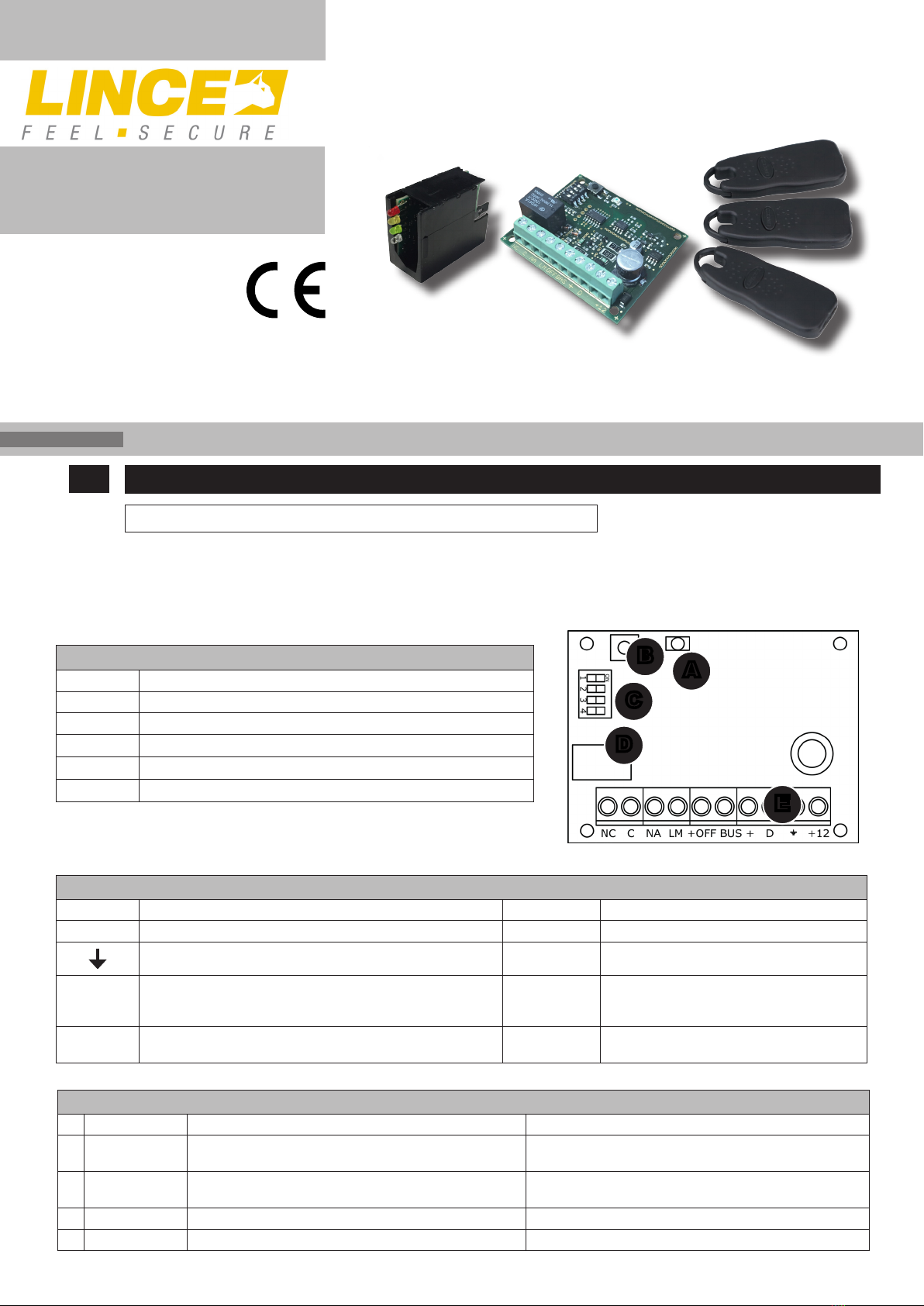
Lince 4037S137PLUS User manual

IT SCHEDA CHIAVE UNIVERSALE CON INSERITORE TRANSPONDER
Manuale di installazione ed uso.
INTRODUZIONE
La S137 PLUS è una scheda universale di gestione chiavi elettroniche che dispone di un relè di uscita da 10 A e di un’uscita di
manomissione del BUS; dispone anche di due ingressi denominati LM e +OFF utili per integrare la scheda in qualsiasi impianto di allarme.
E’ collegabile esclusivamente alla linea di inseritori transponder della serie EUROPLUS.
DESCRIZIONE DEI MORSETTI
MORSETTO DESCRIZIONE MORSETTO DESCRIZIONE
+12 Alimentazione (10 Vcc÷15 Vcc) +Alimentazione per BUS inseritori
massa di riferimento DLinea dati BUS inseritori
LM Ingresso linea aperta settabile BUS
Uscita Open Collector attiva in caso di ag-
giunta/rimozione periferiche o apertura del
morsetto AS dell’inseritore
+ OFF Se collegato ad una variazione di massa, indica l’effettivo
stato impianto C, NC, NA Uscita relè mono/bistabile
Fig. 1
DESCRIZIONE DELLE
PARTI DELLA SCHEDA
PARTE DESCRIZIONE
ALED di visualizzazione
BTasto di programmazione
CDip-switch per le impostazioni
DRelè
EMorsettiera
C
A
B
E
D
IMPOSTAZIONE DEI DIPSWITCH
n° DECRIZIONE OFF ON
1 Uscita BUS Massa normalmente presente morsetto aperto quando si attiva
l’uscita
Morsetto normalmente aperto,
commuta a massa quando si attiva l’uscita
2 Ingresso LM Necessita della massa per attivare il lampeggio del LED
inseritore (solo con Dip4 Off)
Il lampeggio del LED inseritore si attiva con il morsetto
appeso (Solo con Dip4 Off)
3Ingresso
OFF LED acceso con morsetto appeso (solo con Dip4 ON) LED acceso con positivo presente appeso (solo con Dip4
ON)
4 Uscita Relè C, NC, NA = Bistabile C, NC, NA = Impulsato 1 s
Manuale di installazione ed uso.
MADE IN ITALY La dichiarazione CE del presente articolo è reperibile su sito www.lince.net.
Via Variante di Cancelliera, snc
00072 ARICCIA (Roma)
Tel. +39 06 9301801
Fax +39 06 930180232
[email protected] www.lince.net
ART. 4037S137PLUS
001530/00130AF Rev0
SCHEDA CHIAVE UNIVERSALE

SIGNIFICATO DEI LED
Respiro bianco BUS acquisito / stand-by
Sequenza giallo-rosso-verde blu
(supercar) BUS non collegato
Lampeggio bianco-rosso Tamper inseritore aperto
Lampeggio bianco Anomalia su BUS - acquisire BUS
sulla scheda
LED giallo-rosso-verde
accesi ssi
Conferma di avvenuta memorizza-
zione chiave
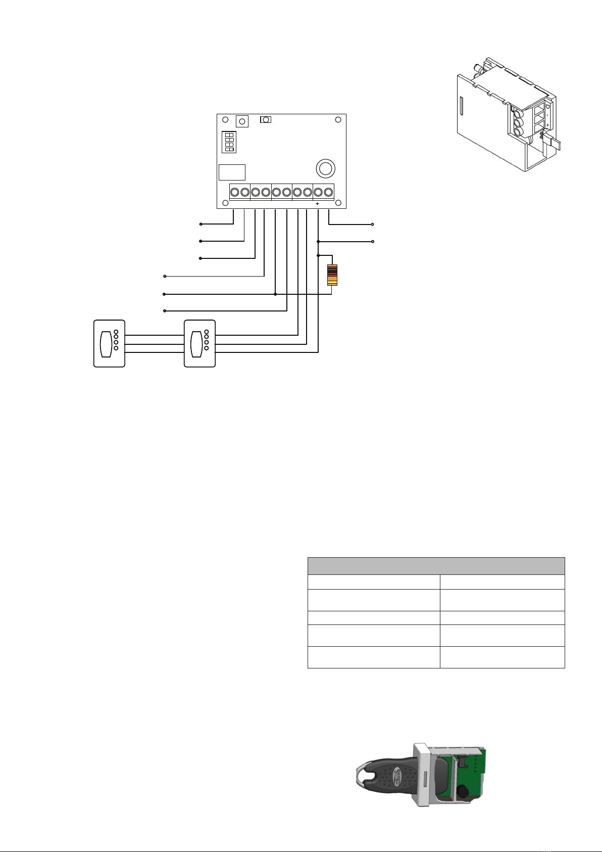
COLLEGAMENTI ELETTRICI ED ESEMPIO DI COLLEGAMENTO
Al ne di effettuare opportunamente e agevolmente i collegamenti elettrici, collegare alimentazione,
massa e dati tra la scheda inseritore e la scheda interfaccia rispettando le serigrae riportate su
entrambe le schede. Collegare quindi i morsetti ingresso/uscita ai relativi dispositivi esterni.
NOTA:
Collegare la massa degli inseritori all’unica massa presente sulla scheda interfaccia
MEMORIZZAZIONE CHIAVI
Per memorizzare le chiavi transponder seguitre i passi riportrati
• Premere e rilasciare il tasto di programmazione; il LED rosso a
bordo scheda lampeggia lentamente (timeout di 1 minuto) ed i
LED degli eventuali inseritori collegati si spengono.
• Inserire in un qualsiasi inseritore collegato al BUS la chiave da
memorizzare.
• Si ottiene un breve lampeggio se la chiave non è ancora
memorizzata; si ottiene un lampeggio di riuto permanente
(nchè la chiave rimane inserita) se già memorizzata
• Estrarre la chiave per memorizzarla.
• Ripetere la sequenza per tutte le chiavi (max. 40)
• Per uscire dalla programmazione senza attendere il timeout
premere brevemente il tasto di programmazione.
RESET INIZIALE
Procedere come descritto di seguito:
• A scheda disalimentata, premere, e mantenere premuto, il tasto di programmazione B.
• Alimentare la scheda continuando a tenere premuto il tasto di programmazione Bper almeno 3 secondi, quindi rilasciare il tasto.
NOTE:
Tutti i codici presenti sulla scheda saranno cancellati così come tutte le periferiche precedentemente memorizzate sulla linea BUS;
ACQUISIZIONE DEL BUS
Per effettuare l’acquisizione sul BUS sarà sufciente alimentare la scheda che entro 30’’ congurerà automaticamente la mappa degli
inseritori. Per tutti i 30’’, necessari, si avrà il lampeggio rapido del LED rosso.
NOTE:
• Per aggiungere, rimuovere e/o sostituire inseritori, disalimentare la scheda e rialimentarla. Al termine delle operazioni si avrà la
nuova mappatura del BUS.
• Il numero massimo degli inseritori collegabili è denito dalla corrente prelevabile dalla centrale di comando o alimentazione
remota alla quale viene collegata la scheda S 137 PLUS (ogni inseritore assorbe in media 34 mA).
Fig. 2
Fig. 3
NC C NA LM +OFF BUS + D +12
1 2 3 4
ON
Scambio relè modalità
Impulsiva o passo passo in
funzione del jumper
LM: Ingresso
+OFF: Ingresso
BUS: Uscita elettrica
Alimentazione 10÷150 Vcc
Massa (comune)
ATTIVAZIONE
• Inserire la chiave e premerla verso l’inseritore no al click, si accenderà
solo il LED rosso;
• successivamente estrarre la chiave.
DISATTIVAZIONE
• Inserire la chiave e premerla verso l’inseritore no al click, si spegnerà
solo il LED rosso;
• successivamente estrarre la chiave. Fig. 4
MADE IN ITALY
Resistore da 1 kOhm (in dotazione, colori
marrone, nero, rosso) per la gestione
dell’ingresso + OFF

EN UNIVERSAL KEY WITH KEYREADER
Installation and operation manual.
DESCRIPTION
The S137 PLUS is a universal electronics board for managing electronic keys that has a 10 A output relay and an output of the BUS
tamper; it also has two inputs called LM and + OFF that are useful to integrate the card into any alarm system. It can only be connected to
the EUROPLUS transponder key readers.
TERMINAL BLOCK DESCRITPION
TERMINAL DESCRIPTION TERMINAL DESCRIPTION
+12 Power supply (10 Vcc÷15 Vcc) +BUS power supply for keyreader
Ground DKeyreader BUS line
LM Open line input settable BUS
Open Collector output active in case of adding
/ removing peripherals or opening of the AS
terminal of the keyreader
+ OFF If connected to a mass variation, indicates the actual
state of the system C, NC, NA bistalbe/step-by-step relè output
Fig. 5
BOARD PART DESCRIPTION
PART DESCRIPTION
AVisualization LED
BProgramming switch
CDip-switches for settings
DRelè
ETerminal block
C
A
B
E
D
Manuale di installazione ed uso.
MADE IN ITALY The CE declaration of this item is available on www.lince.net website.
Via Variante di Cancelliera, snc
00072 ARICCIA (Roma)
Tel. +39 06 9301801
Fax +39 06 930180232
[email protected] www.lince.net
ART. 4037S137PLUS
001530/00130AF Rev0
DIPSWITCH DESCRIPTION
n° DESCRIPTION OFF ON
1 BUS output Ground normally present, terminal block opened when the
output is activated
Terminal block normally open,
switches to ground when the output is activated
2 LM input It requires a ground signal to activate the ashing of the
LED keyreader (only with D4 Off)
The ashing of the LED activates with the hanging terminal-
block (Only with D4 Off)
3 OFF input LED on with hanging terminal block (only with D4 ON) LED on with hanging present positive (only with D4 ON)
4 Relè output C, NC, NO = step-by-step C, NC, NO = pulsed 1 s
UNIVERSAL KEY

LEDs MEANING
White breath BUS acquisito / stand-by
Blue yellow-red-green sequence
(Supercar) BUS not connected
White-red ashing Keyreader tamper opened
White ashing BUS anomaly - acquire BUS on the
board
LED yellow-red-green
xed on
Conrmation of the complete
key memorization
ELECTRICAL CONNECTIONS AND CONNECTION EXAMPLE
In order to make the electrical connections conveniently and easily, connect the power supply, ground and
data between the keyreader board and the interface board, respecting the silk-screen printed on both boards.
Then connect the input / output terminals to the relevant external devices.
NOTE:
Connect the mass of the keyreaders to the only mass on the interface board
KEYS STORING
To store the keys, follow the steps reported below
• Press and release the programming button; the red LED on the
board ashes slowly (timeout of 1 minute) and the LEDs of any
connected readers is switched off.
• Insert the key to be stored in any keyreader connected to the
BUS.
• A short ash is obtained if the key is not yet stored; you get a
ash of permanent rejection (until the key remains inserted) if
already stored
• Extract the stored key.
• Repeat the sequence for all the keys (max 40)
• To exit programming without waiting for the timeout, briey
press the programming key.
INITIAL RESET
Proceed as described below:
• With the board disconnected, press and hold the programming key B.
• Power up the card while continuing to hold down the programming button Bfor at least 3 seconds, then release the button.
NOTE:
All the codes on the card will be deleted as well as all the peripherals previously memorized on the BUS line;
BUS STORAGE
To carry out the acquisition on the BUS it will be sufcient power supply the board that within 30’’ will automatically congure the map of
keyreaders. For all 30 ‘’, necessary, you will have the rapid ashing of the red LED.
NOTE:
• To add, remove and / or replace the keyreader, switch off the board and switch it on again. At the end of the operations, the new BUS
mapping will be performed.
• The maximum number of connectable keyreaders is dened by the current available from the control unit or remote power supply to
which the S 137 PLUS board is connected (each inserter absorbs an average of 34 mA).
Fig. 6
Fig. 7
NC C NA LM +OFF BUS + D +12
1 2 3 4
ON
Mode relay exchange
Impulsive or step by step
jumper function
LM: Input
+OFF: Input
BUS: electrical output
10÷15 Vdc power supply
Ground (common)
ARMING
• Insert the key and press it towards the key reader until it clicks, only
the red LED will light up;
• then extract the key.
DISARMING
• Insert the key and press it towards the key reader until it clicks, only
the red LED will go out;
• then extract the key. Fig. 8
1 kOhm resistor (supplied, colors brown,
black, red) for the management of the + OFF
input
Table of contents
Languages:
Other Lince Remote Control manuals