Page Number - 10 Form 823094
Applications et essentiel des tests
Le appareil de contrôle de pression du système de refroidisse-
ment MV4529 est destiné à diagnostiquer et à localiser la
présence de fuites dans un système de refroidissement
d’automobile. Il contient l’équipement nécessaire pour mettre
sous pression et surveiller un système de refroidissement manu-
ellement. Les fuites sont indiquées par une chute de pression
de quelques secondes ou minutes. L’emplacement de fuite(s)
externe(s) se reconnaît par le suintement visible du liquide sous
l’effet de la pression. Les fuites internes, qui peuvent ne pas être
visibles, sont causées typiquement par un joint de culasse sauté
ou
par un bloc ou une culasse endommagé et peuvent être
diagnostiquées en surveillant la pression pendant un test rapide
avec le moteur en marche.
Le MV4529 peut aussi servir à tester les bouchons à soupape
de pression du système de refroidissement utilisant une valve de
décharge comme protection contre la surpression. Un
bouchon défectueux peut causer une surpression ou une
sous-pression du système de refroidissement et provoquer
une surchauffe et/ou endommager sérieusement le moteur.
Ce test est réalisé en utilisant la pompe à pression incluse
dans ce kit, mais il exige aussi des adaptateurs de test de
bouchon qui ne sont pas inclus dans ce kit et qui doivent être
achetés séparément. Refer to the Adapter Selection Guide
included in the kit for more information on cap adapters.
Précautions
L’équipement de test a pour but d’effectuer les procédures de
service pour une variété de véhicules sans danger et facilement.
Cependant certains des tests indiqués dans ces directives
peuvent ne pas pouvoir être exécutés sur tous les véhicules à
cause des différences entre les systèmes de refroidissement.
Les procédures figurant dans ce manuel sont destinées à ser-
vir de directives pour l’utilisation de cet équipement. Outre ces
directives, suivez toujours les procédures recommandées par le
constructeur pour le service de chaque véhicule. N’essayez pas
de forcer un test sur un système de refroidissement pour lequel
cet équipement n’est pas prévu.
L’exécution de tests de système de refroidissement en utilisant
le MV4529 est simple et facile à condition de suivre les
directives. Cependant, n’oubliez pas que le système peut être
rempli de liquide froid ou chaud sous pression, prêt à être expul-
sé. Si un test est exécuté sur un moteur qui est chaud et/ou
sous pression, réfléchissez toujours avant de retirer un bouchon
ou de déconnecter un tuyau ou une autre pièce.
Lisez toujours attentivement et comprenez les instructions avant
d’utiliser l’équipement.
Portez toujours des lunettes de protection pour retirer le
bouchon du radiateur ou de la bouteille du liquide de refroidisse-
ment, ou en effectuant un test quelconque sur
le système de refroidissement.
Ne retirez jamais le bouchon du radiateur ou de la bouteille de
liquide de refroidissement et n’essayez pas de mettre sous
pression le système de refroidissement d’un véhicule qui est
surchauffé.
Laissez toujours le système refroidir avant de réaliser une procé-
dure de test en rapport avec le système de refroidissement.
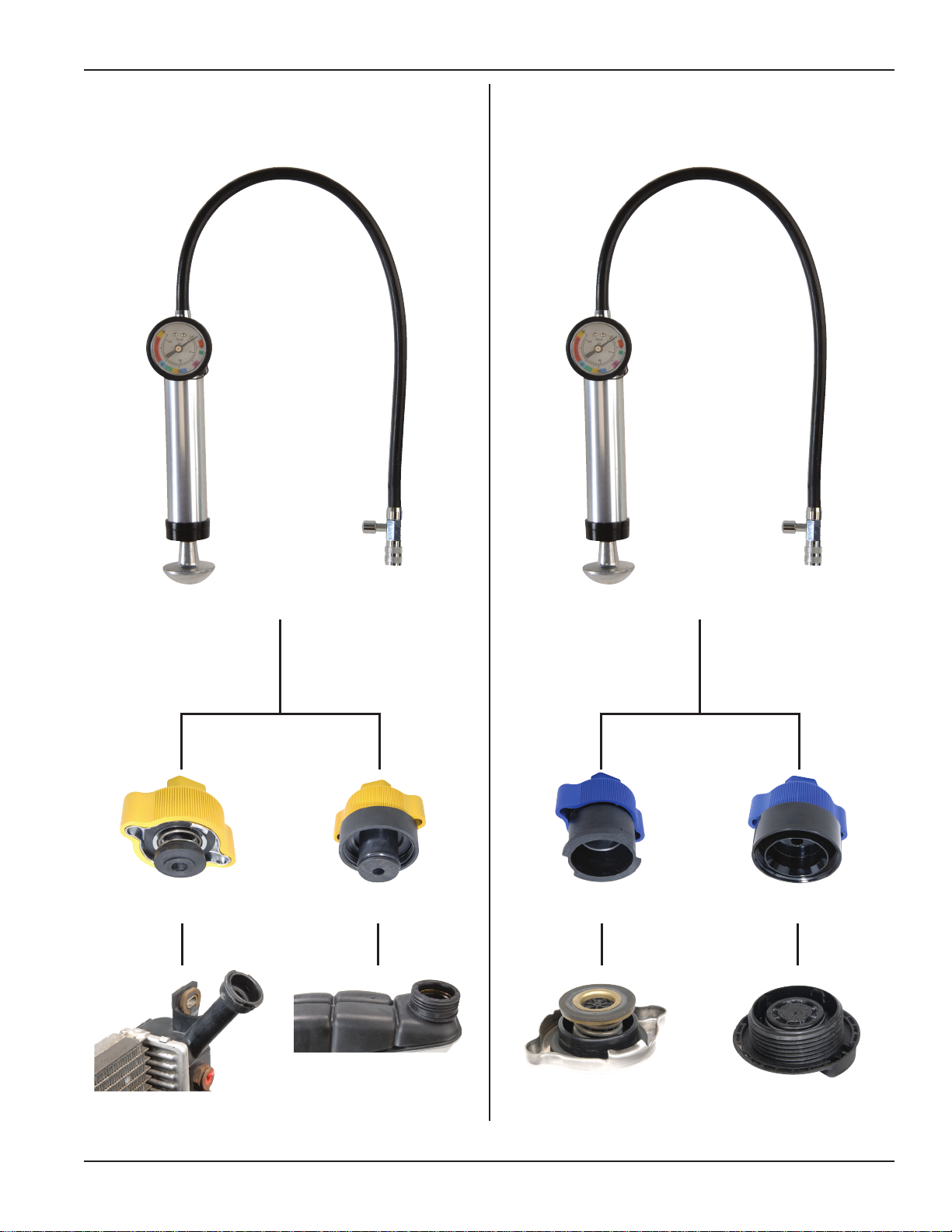
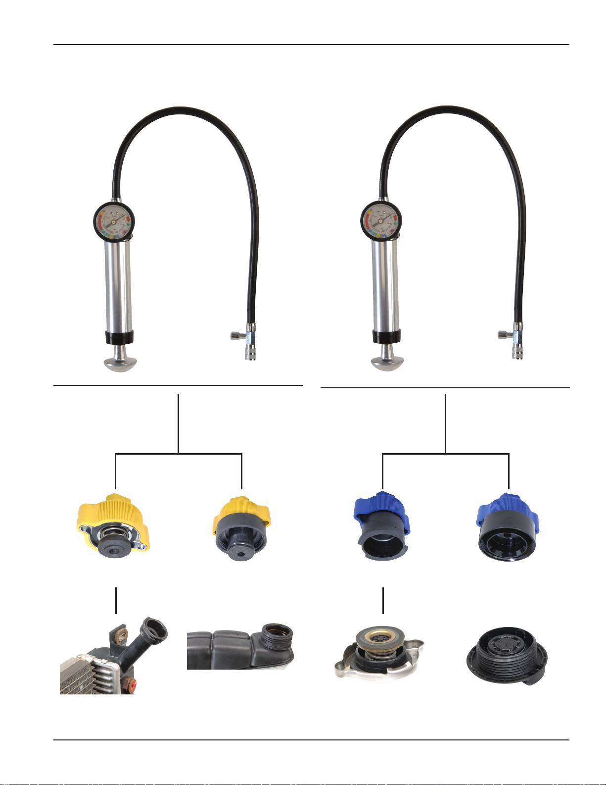
Tests
Pour décider où établir la connexion avec le système de
refroidissement, regardez d’abord le radiateur et déterminez
s’il a un goulot de remplissage et un bouchon à soupape de
pression. Cette configuration est habituelle sur environ la moitié
des véhicules fabriqués aux États-Unis et presque sur tous les
véhicules fabriqués en Asie, et est l’emplacement de premier
choix pour établir la connexion. Si le radiateur est fermé et
inaccessible, la connexion doit se faire par la bouteille de liquide
de refroidissement. Certains systèmes de refroidissement util-
isent une bouteille de trop-plein de liquide de refroidissement qui
ne fait pas partie du système étanche. Si vous essayez de tester
le système de refroidissement par cette bouteille, la
connexion avec le système étanche ne se fera pas et cela aura
pour résultat de faire passer simplement la pression ou le vide
du test dans l’atmosphère. Ce type de bouteille de trop-plein se
reconnaît facilement au bouchon encliquetable ou au bouchon
fileté ouvert vers l’atmosphère. Il n’existe pas d’adaptateurs
pour convenir à ce type de bouteille de trop-plein de liquide de
refroidissement. La connexion pour exécuter le test doit se faire
par un radiateur ou une bouteille de liquide de refroidissement
avec un modèle de bouchon à baïonnette ou fileté fabriqué
spécialement pour maintenir une pression spécifique dans le
système de refroidissement.
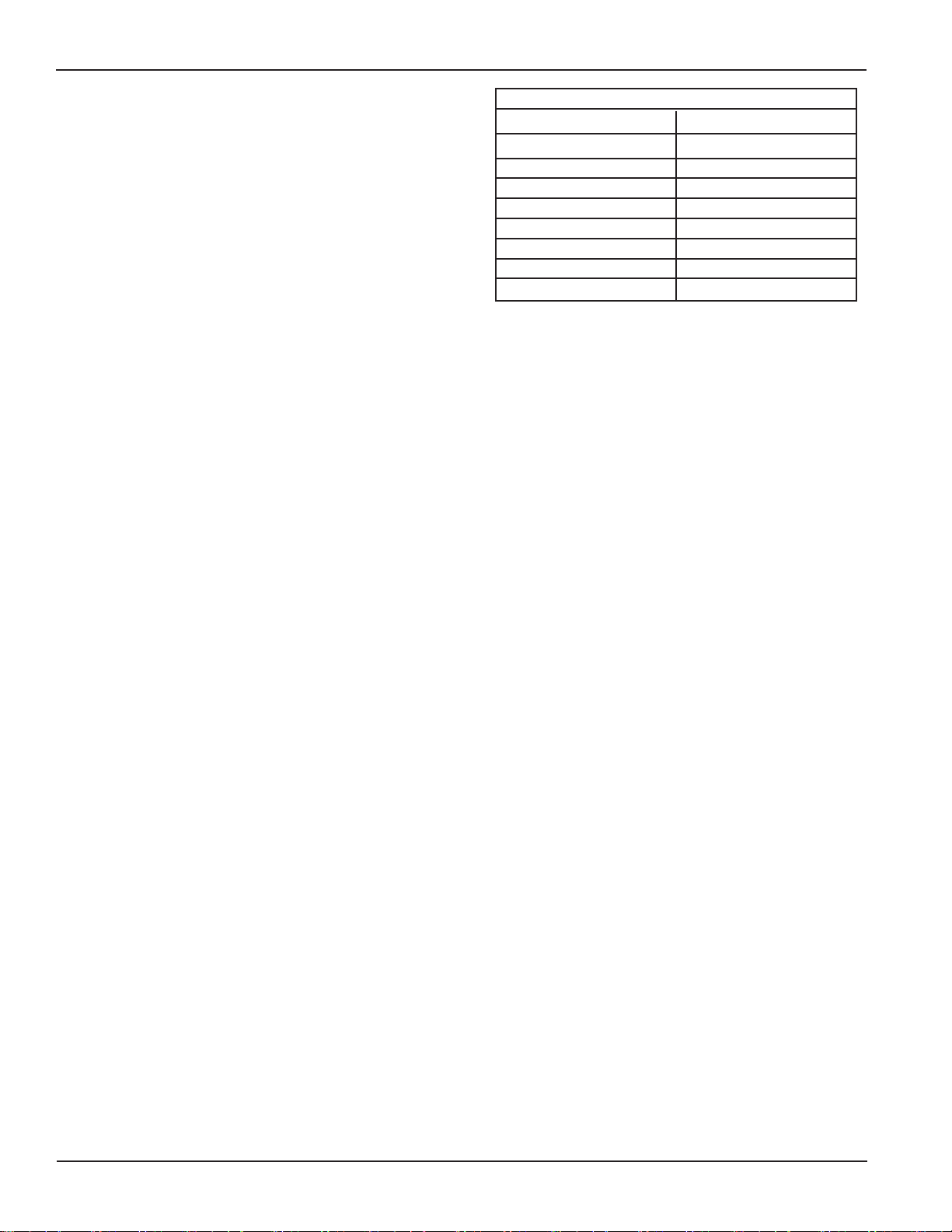
Adaptateurs
Le MV4529 inclut un adaptateur de type à baïonnette pour le
système de refroidissement pour installation sur les voitures
et camionnettes américaines de modèle ancien et sur cer-
tains modèles récents. Cet adaptateur ou un autre est néces-
saire pour brancher l’équipement d’essai sur le système de
refroidissement d’une marque et d’un modèle spécifique. Des
adaptateurs supplémentaires sont offerts séparément pour
d’autres véhicules de constructeurs américains, asiatiques et
européens. Consulter, dans le Guide de sélection d’adaptateurs
inclus dans ce nécessaire, la liste des adaptateurs pour utilisa-
tion sur tous les systèmes et bouchons offerts par MityVac.
Quand l’adaptateur correct pour le véhicule est identifié, il est
possible de l’utiliser pour faire tous les essais mentionnés dans
ce manuel.