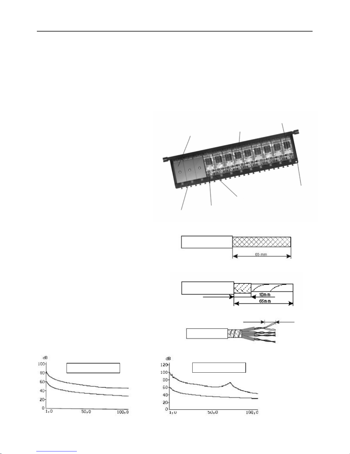
Lindy GIGAPATCHPANEL 20703 User manual

© LINDY ELECTRONICS LIMITED & LINDY-ELEKTRONIK GMBH -FIRST EDITION ( Jul 2001)
GigaPatchPanel
Manual English
Benutzerhandbuch Deutsch
Manuel Français
Manuale Uso Italiano
LINDY Art.No. 20703
LINDY Art.No. 20704
www.LINDY.com

English Manual
Module Cover Terminals 2-Port-PCB
Chassis
Shielding Contact
Strain Relief
Ground Connector
LINDY GigapatchPanel
The LINDY GigaPatchPanel is supplied with 16 or 24 Cat 6 ports. The new modular construction allows you to
install the panels with any even number of ports between 2 and 24, partially equipped panels can be extended or
completed with the addition of dual modules at any time. This means that the valuable space inside your rack can
be fully optimised, for the future expansion of your network.
The newly developed LSA-rct technology allows a fast and reliable connection of the wires to the terminals. Each
unit is supplied with a suitable crimping tool, however there is also a premium tool available which allows you to
connect 4 wires simultaneously and thus helps to increase efficiency and lower the costs of the network installation.
?Up to 12 shielded dual RJ45 Cat 6 modules per unit
?PCB-terminals optimised for fast data transfer
?Strain relief’s are attached -so they won’t get lost
?Additional strain relief by use of a cable tie is possible
?Coding scheme both, EIA/TIA 568 A and B
?Crimping tool supplied
?Connection via LSA-rct terminals
?Cores with 22-24 AWG can
be accommodated
?Pairs can be lead
directly to the terminals
–no need to untwist
them
Preparation of the cable
Foil-or Braid shielded cable
Cut away the outer sheath by approx 65mm with a
cable or sharp knife. Make sure to cut only as deep as
the shielding allows, don’t damage the insulation of the
wires!
Cut the foil or the braid shielding as shown in the
picture so that you leave approx 10mm of the shielding.
Wind the shielding wire around the 10mm left of the
shielding, it will be clamped later beneath the strain
relief.
If present, shorten the shielding foil of the single pairs
(Pimf-cable only) to the same length. Untwist the pairs
for 13mm at most and connect the wires using the
followingcolourscheme
untwist 13 mm at most
NEXT –Pairs 1,2 –3,6
NEXT
–
Pairs 3,6
–
4,5

English Manual
Mounting
1. Mount the strain relief and the shielding braid or
foil as shown in the picture. The flexible strain
reliefs will avoid squeezing the solid core cables
too heavily.
2. Connect the individual wires
Note: The colour schemes TIA 568-Aand TIA 568-B
must not be mixed within one network structure
3. Snap in the cover 4. Mount the cover screw
Pinout of a module confirming ISO/IEC 11081 Colour scheme for 100Base-T and 1000BaseT
Jack
Pin # Wire colour
EIA/TIA 568A Wire colour
EIA/TIA 568B
1green/white orange/white
2green orange
3orange/white green/white
4blue blue
5blue/white blue/white
6orange green
7brown/white brown/white
8brown brown
Terminals
Terminals
Jack Jack
Ground
connector

Deutsches Benutzerhandbuch
Moduldeckel Klemmen 2-Port-Platine
Chassis
Schirmkontakt
Zugentlastung
Erdungsanschluß
LINDY GigaPatchPanel
Die LINDY GigaPatchPanels sind standardmäßig mit 16 oder 24 Cat.6-Ports bestückt. Durch das neuartige modulare Konzept
können Panels mit jeder geraden Anzahl Ports zwischen 2 und 24 bestückt, und anteilig bestückte Panels jederzeit mit den
Einzelmodulen nachgerüstet werden. Der wertvolle Platz im Server-Rack läßt sich somit zukunftsorientiert und offen für
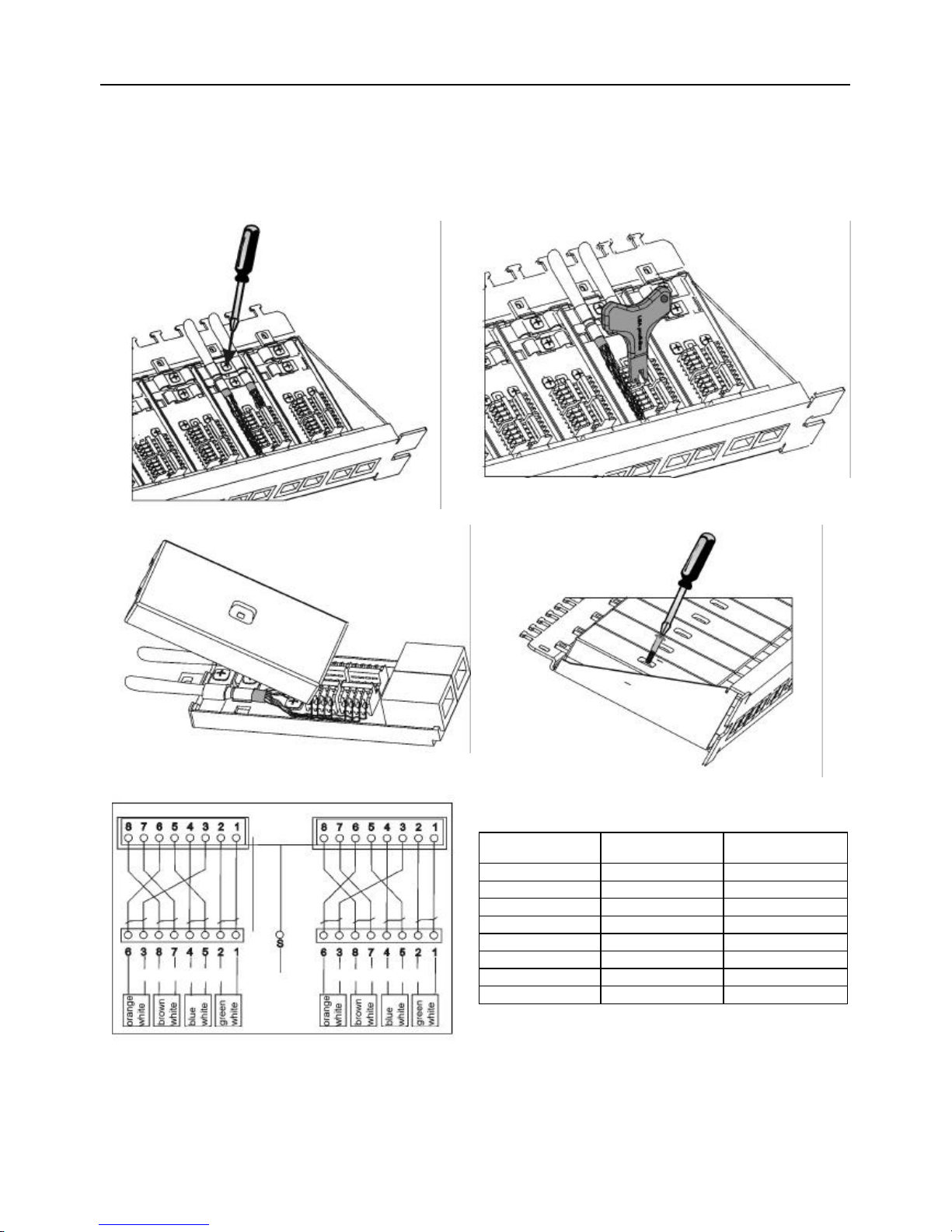
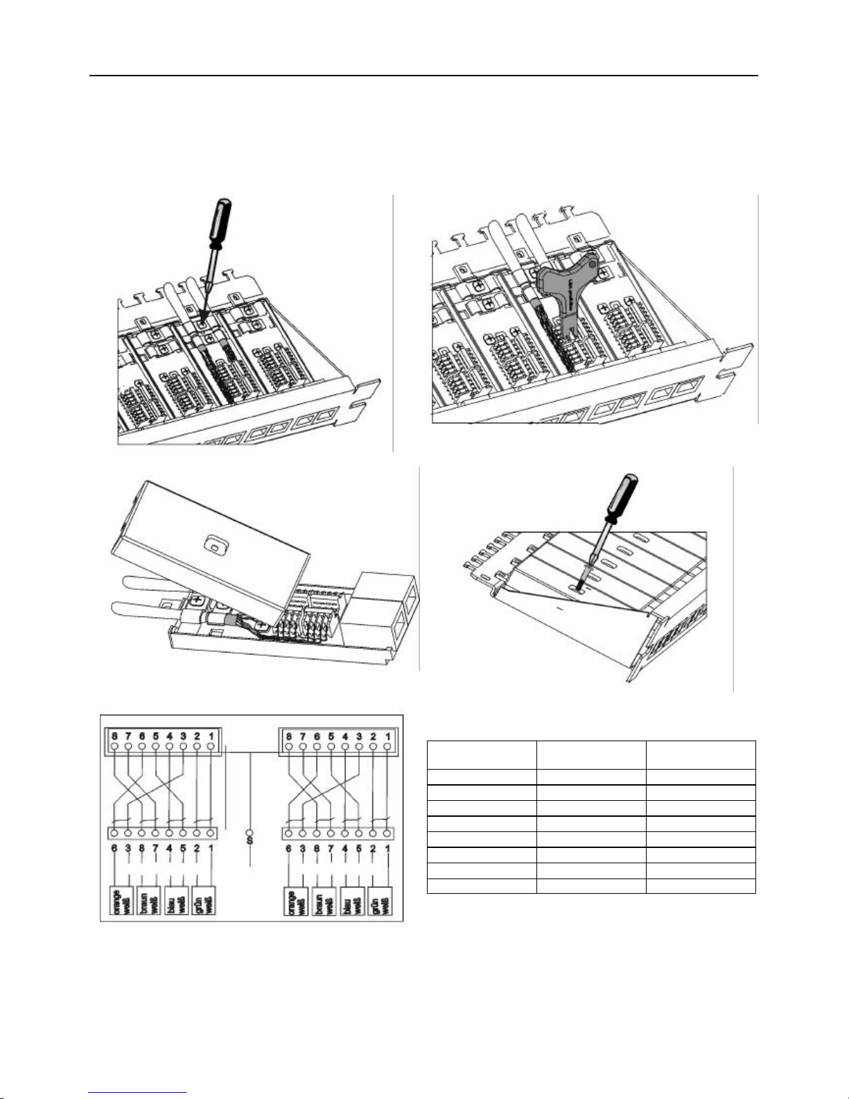
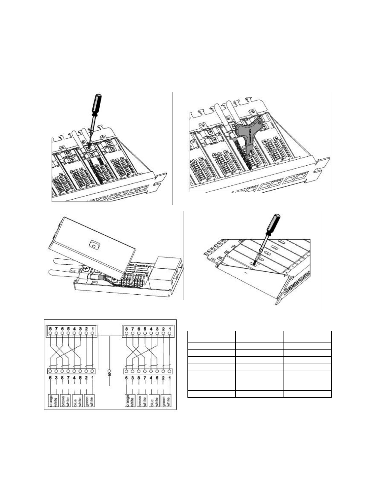
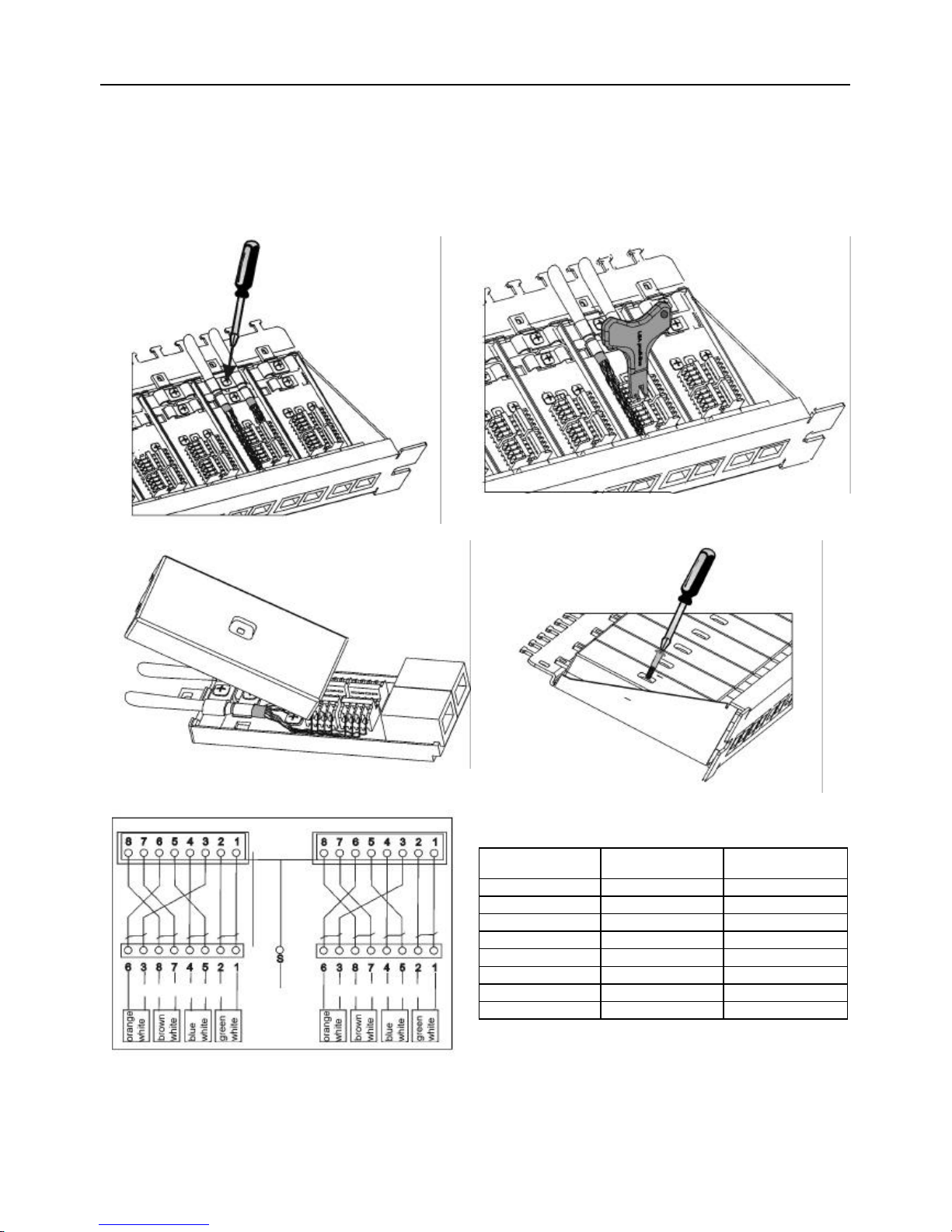
künftige Erweiterungen planen. Durch die neu entwickelte LSA-rct-Technologie lassen sich die Panels schnell und problemlos
beschalten. Jedem Panel liegt ein Anlegewerkzeug bei, wahlweise kann jedoch auch die Premiumversion (LINDY Art. Nr.
20708) verwendet werden, die ein Anlegen von simultan vier Drähten gestattet. Die Beschaltung der Panels gestaltet sich
dadurch noch effizienter und hilft so, die Installationskosten niedrig zu halten.
?bis zu 12 einzeln abgeschirmte Module zu je 2 RJ45-Cat 6-Anschlüssen
?Optimierte Leiterplatten-Anschlussklemmen für schnelle Datenübertragung
?Zugentlastung mittels 'unverlierbarer' Kabelschellen
?zusätzliche Zugentlastung mittels Kabelbinder möglich
?Übersichtliche Farbcodierung nach EIA/TIA 568 A/B
?Anlegewerkzeug im Lieferumfang
?Beschaltung nach ISO/IEC 11801 /EN 50173
?AnschlussmittelsLSA-Schneidklemmen
?Beschaltung mit Drähten AWG 22-24
?Adernpaare können bis zur
Klemme geführt werden, ohne
daß die Verdrillunggelöst
werden muss
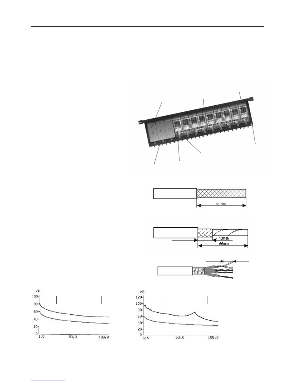
Die Kabelvorbereitung
KabelmitGeflecht-oder Folienschirm
Setzen Sie den Kunststoffmantel ca. 65mm mit einem
Kabel-oder Teppichmesser ab. Achten Sie darauf, nur
bis zur Schirmung zu schneiden, damit die Adern nicht
verletzt werden.
Schneiden Sie das Schirmgeflecht, bzw. Schirm-und
Kunststoffolie so ab, dass noch ca. 10 mm unter dem
Kuststoffmantel hervorschauen. Wickeln Sie den
Beilaufdraht um die verbleibenden 10mm Schirmung,
er wird später unter der Schelle mit festgeklemmt
Falls vorhanden, kürzen Sie die Schirmfolie der
einzelnen Paare (PiMF-Kabel) auf die gleiche Länge.
Entdrillen Sie die Paare maximal auf eine Länge von
13mm und legen Sie die Adern nach dem
vorgegebenen Farbschema auf. Verwenden Sie in
Ihrem Netzwerk stets nur eines der beiden
angegebenen Farbschemata. Niemals mischen!!!
Maximal 13 mm entdrillen
NEXT –Pairs 1,2 –3,6
NEXT
–
Pairs 3,6
–
4,5

Deutsches Benutzerhandbuch
Montage
5. Befestigen Sie die Kabelzugentlastung und das
Schirmgeflecht wie abgebildet. Die flexiblen
Kabelschellen vermeiden ein zu starkes
Quetschen der Verlegekabel.
6. Legen Sie die einzelnen Drähte auf
Achtung: Die Farbcodes TIA 568-A und TIA 568-B
dürfen innerhalb einer Netzwerkstruktur nicht
gemischt werden.
7. Deckel einrasten 8. Deckel verschrauben
Pinout eines Moduls nach ISO/IEC11801 Klemmenbelegung für 100Base-T und 1000Base-T
Patchfeld
Anschlußklemme Adernfarbe nach
EIA/TIA 568A Adernfarbe nach
EIA/TIA 568B
1grün/weiß orange/weiß
2grün orange
3orange/weiß grün/weiß
4bau blau
5bau/weiß blau/weiß
6ornge grün
7braun/weiß braun/weiß
8braun braun
Anschlußklemmen
Anschlußklemmen
Buchse Buchse
Schirmanschluß

Manuel en Français
Capot Terminaux 2-Port-PCB
Chasis
Blindage contacts
Serre-câbles
Connecteur Terre
Panneau de brassage LINDY GigaPatch
Le panneau de brassage LINDY GigaPatch est livré avec 16 ou 24 ports Cat 6. La nouvelle conception modulaire
du panneau de brassage vous permet une installation allant de 2 à 24 connexions, les emplacements de ports
vides pourront être complétés à tout moment par des modules supplémentaires. Ceci implique des possibilités
d’extension pour votre rack même déjà en place.
La nouvelle technologie LSA-rct vous permet une connexion rapide et fiable des fils aux terminaux.
Chaque unité est fournie avec une pine à sertir adaptée, cependant il existe également un outil à sertir de haute
qualité vous permettant de connecter 4 fils simultanément, augmentant l’efficacité et baissant les coûts
d’installation de votre réseau.
?Jusqu’à 12 modules doubles blindés RJ45 Cat 6 par unité
?Terminaux PCB optimisés pour transfert de données rapides
?Les câbles sont attachés par des serre-câbles –ils ne se perdront pas
?Possibilité d’ajouter des serre-câbles supplémentaires
?Schéma de codage EIA/TIA 568 A et B
?Outil de sertissage fourni
?Connexions par terminaux LSA-rct
?Compatible câbles
AWG22/24
?Les paires sont
directement connectées
aux terminaux –pas
besoin de les dénuder
Préparation du câble
Câble blindé torsadé
Coupez la gaine du câble sur approximativement
65mm avec un cutter ou une lame. Soyez certains de
couper jusqu’au blindage, n’endommagez pas la gaine
des fils intérieurs!
Coupez la feuille d’aluminium ou le blindage comme
indiqué sur l’image ci-contre pour laisser
approximativement 10mm du blindage. Veuillez laisser
dépasser la feuille d’aluminium de 10mm de la gaine,
elle sera serrée avec l’aide du serre-câbles.
Si présent, raccourcissezle blindage de la paire (câble
Pimf uniquement) à la même longueur. Dénudez les
paires sur environ 13mm au maximum et connectez-
les en utilisant le schéma de codage couleur ci-
dessous.
Dénudez 13 mm au maximum
SUIVANT –Pairs 1,2 –3,6 SUIVANT –Paires 3,6 –4,5

Manuel en Français
Montage
9. Vissez le serre-câbles sur vos câbles.
Le serre-câbles vous évitera une torsion inutile du
câble dans la section du connecteur.
10. Connectez individuellement les fils
Remarque: Les code à couleurs des normes
TIA 568-A et TIA 568-B ne doivent pas être
mélangés dans une installation réseau.
11. Insérez le capot 12. Revissez le capot
Brochage d’un module ISO/IEC 11081 Schéma des couleurs pour 100Base-T et 1000BaseT
Jack
Broche # Couleur de fil
EIA/TIA 568A Couleur de fil
EIA/TIA 568B
1vert/blanc orange/blanc
2vert orange
3orange/blancvert/blanc
4bleu bleu
5bleu/blanc bleu/blanc
6orange vert
7brun/blanc brun/blanc
8brun brun
Terminal
Terminal
Jack Jack
Terre

Manuale in Italiano
Coperchi Terminali 2-Porte-PCB
Telaio
Contatti schermati
Bloccacavo
Presa di terra
LINDY GigaPatchPanel
Il LINDY GigaPatchPanel è fornito con 16 o 24 porte Cat.6. La nuova struttura modulare, consente l’installazione di
un numero pari di porte, comprese tra 2 e 24. Ciò significa che lo spazio all’interno del mobile rack può essere
ottimizzato per eventuali ampliamenti della rete.
La nuova tecnologia LSA-rct consente una veloce ed affidabile connessione dei cavi ai terminali. Ciascuna unità
viene fornita con gli appositi attrezzi di montaggio.
?Fino a 12 moduli RJ45 Cat 6 doppiamente schermati per unità
?Terminali PCB ottimizzati per il trasferimento veloce dei dati
?Blocca cavi inclusi
?Schemi di codifica EIA/TIA 568 A e B
?Set crimpaggio
?Connessione via terminali LSA-rct
?Cavi AWG 22-24
alloggiabili
?Possibilità di collegare
cavi twistati
Preparazione del cavo
Tagliare la copertura esterna del cavo per circa 65mm.
Attenzione a non danneggiare la parte interna del cavo.
Eliminare la schermatura d’alluminio per circa 55mm
dalla fine, lasciandone quindi circa 10 dall’estremità
interna.
Eliminare l’eventuale schermatura dei singoli cavetti e
liberare i singoli cavetti, dalle coppie ritorte per circa
13mm dall’estremità finale.
Untwist 13 mm maximum
NEXT
–
Pairs 1,2
–
3,6
NEXT
–
Pairs 3,6
–
4,5

Manuale in Italiano
Montaggio
13. Montare i blocca cavi come illustrato in figura. 14. Collegare I singoli cavetti.
Nota: Seguire lo schema a colori TIA 568-A e B.
Non mischiare schemi e colori all’interno di un
singolo sistema network.
15. Chiudere il coperchio 16. Montare le viti
Pinatura conforme a ISO/IEC 11081 Schema colori per 100Base-T e 1000BaseT
Jack
Pin # Colore cavo
EIA/TIA 568A Colore cavo
EIA/TIA 568B
1verde/bianco arancio/bianco
2verde arancio
3arancio/bianco verde/bianco
4blu blu
5blu/bianco blu/bianco
6arancio verde
7marrone/bianco marrone/bianco
8marrone marrone
Terminals
Terminals
Jack Jack
Ground
connector

Technical Specifications
Number of Ports:
Up to 24 by using up to 12 dual Cat. 6 modules
Wiring: Confirming ISO / IEC 11801 / EN 50173
Wire Gauge: Cores of AWG 22 –24 can be accomodated
Coding Scheme: Both, EIA/TIA 568 A and B
Terminals: LSA –rct (rapid contact technology)
Ports:
Data ports up to Cat. 6 can be established
Maintanance: One module can be opened for maintenance or without
influencing all the other modules, on which network trafiic is
still running.
Strain reliefs:
Attached strain reliefs –no way for them to get lost
Additional Strain Relief: Optional with a cable tie
Crimping tool:
Supplied with every unit
PCB:
Optimised for fast data transfer
Rackmount Kit:
Mounted to every unit
Housing:
Completely made from steel sheet


© LINDY ELECTRONICS LIMITED & LINDY-ELEKTRONIK GMBH -FIRST EDITION ( Jul 2001)
www.LINDY.com
This manual suits for next models
1
Table of contents
Languages:
Other Lindy Computer Accessories manuals