manuals.online logo
Brands
  1. Home
  2. •
  3. Brands
  4. •
  5. Linear Technology
  6. •
  7. Motherboard
  8. •
  9. Linear Technology DC708 User manual

Linear Technology DC708 User manual

QUICK START GUIDE FOR DEMONSTRATION CIRCUIT DC708
LITHIUM-ION LINEAR BATTERY CHARGER WITH THERMAL REGULATION
1
LTC4064EMS-4.0

Demonstration circuit DC708 is a complete constant-
current, constant-voltage battery charger designed to
charge one Lithium-Ion cell used in battery backup ap-
plications or applications that require greatly increased
cycle life at the expense of battery capacity. The
LTC4064EMS-4.0 used on this demo circuit features an
internal P-channel power MOSFET with a unique thermal
feedback loop that reduces the output current under
high ambient temperature and/or high power dissipation
conditions. This feature allows the charger to provide
higher charge currents under normal conditions and still
provide safe charging under abnormal conditions such
as high ambient temperature, high input voltage or low
battery voltage. The IC is available in a 10-pin MSOP
thermally enhanced package featuring an exposed bot-
tom-side metal pad for soldering to the PC board.
Other Features include:
•
Preset float voltage of 4.0V±1%.
•
Greatly increased cycle life when used for charging
4.1V or 4.2V batteries.
•
1A and 0.5A Constant Current selected by a jumper.
•
Capable of charging directly from USB power.
•
3-hour charge termination timer. This timer can be set
for other time periods through a capacitor change.
For instance, you may want to use a much shorter pe-
riod (on the order of 30 seconds) when evaluating the
board with a battery simulator instead of a real Li-Ion
battery.
•
Charge Current Monitor Output can be used for gas
gauging.
•
Manual Shutdown
•
Low battery drain current when input supply is re-
moved
•
No isolation diode or current sense resistor required.
•
C/10 Trickle charge for deeply discharged batteries
•
Auto recharge when battery voltage drops below pre-
set threshold
•
Input Power OK LED indicator (ACPR)
•
C/10 Charge LED indicator (CHRG)
•
Fault LED indicator for “out of temp range” (FAULT)
Small surface mount components are used to minimize
board space and height with the circuitry occupying ap-
proximately 0.15 square inches of board space with a
height of 0.054 inches (1.4mm).
Table 1. Typical Demo Board Specifications
Input Voltage Range V
IN
4.25V to 7V (upper
range limited by PC
board dissipation)
Output Voltage V
BAT
(constant
voltage mode)
4.0V ±1%
Output Current I
BAT
(constant
current mode)
1 A ± 8%, 0.5A ± 8%
••••••••••••••••••(se
lected by jumper)
Current Monitor Output
1.5V
±5% @ Full Cur-
rent
Output Current I
BAT
(trickle
current mode)
100mA ± 20%, 50mA ±
20%
C/10 CHRG LED Threshold Level
100mA ± 25%. 50Ma ±
25%
Circuit Board Temperature in
Thermal Feedback Mode
60°C to 70°C
Trickle Charge Threshold
Voltage
2.457V
Battery Drain Current with
V
IN
Removed
<1µA
QUICK START GUIDE FOR DEMONSTRATION CIRCUIT DC708
LITHIUM-ION LINEAR BATTERY CHARGER WITH THERMAL REGULATION
2
     

To save time, we recommend using a battery simulator
(described in Table 2 and Figure 1•) If an actual re-
chargeable Li-Ion battery is used, keep the DC resistance
between the charger and the battery to a minimum, as
this will affect the charge current in the constant voltage
mode.
Table 2. Test Equipment Required for Demo Board Evaluation
Lab Power supply for input power 0 to 7V, 1.2A
Digital voltmeter for measuring
input voltage (VIN)
3 1/2 digits
Digital voltmeter for measuring
battery voltage (VBAT)
4 1/2 digits, resolution to 1mV
Digital voltmeter for measuring
PROG pin voltage (current moni-
tor)
3 1/2 digits, resolution to 1mV
Digital voltmeter for measuring
voltage across current sense resis-
tor (IBAT)
100mV range
4.2V Rechargeable Li-Ion Cell or
Battery Simulator
600mA/Hr to 1.3A/Hr
Battery Simulator Consists of:
Power supply with coarse and fine
output voltage adjust controls
0 to 5V, 2.5A
Power resistor (preload for power
supply)
2
Ω
, 10W
Current sense resistor for measur-
ing charge current
0.1
Ω
, 1%, 1W
Current sense resistor for measur-
ing battery drain current
1k, 1%, 0.5W
SETUP
Refer to Table 2 and Figure 1 for equipment require-
ments and proper setup.
1.
Set jumper JP1 to the “RUN” position (lower posi-
tion).
2.
Set jumper JP2 to the lower position, which programs
the constant charge current to 1A.
3.
Set the input power supply to 0V, and then connect it
to the VIN and GND pins of the demo board.
4.
Set the battery simulator to 0V, and then connect it to
the BAT and GND pins.
5.
Connect the digital voltmeters as shown in the setup
diagram to measure VIN, V(current monitor), charge
voltage (VBAT) and the charge current (IBAT).
EVALUATION
Undervoltage Lockout Feature
•
Increase the input power supply to approximately
3.8V (battery simulator power supply set for 0V).
The charger output voltage and charge current should
be 0. All three LEDs should be off. The charger is in
shutdown due to the undervoltage lockout feature.
Trickle Charge Current
•
Increase the input voltage to 5V and keep the battery
simulator power supply at 0V.
The CHRG and ACPR LEDs should now be on, and the
FAULT LED should be off.
The charger output voltage
(VBAT) should be approximately 240mV, and the
charge current should be about 100mA (10mV on the
charge current DVM). This is the trickle charge mode
for a deeply discharged battery. Typically, a battery
that has not been charged for a long time.
Constant Current Charge
•
Starting at 0V, slowly increase the battery simulator
power supply (VBAT), observing the charger’s output
voltage on the DVM.
When the charger’s output voltage exceeds approxi-
mately 2.45V, the charger will suddenly enter the con-
stant current portion of the charge cycle, resulting in
an abrupt jump in the charge current to the pro-
grammed value of approximately 1.0A (100mV on the
charge current DVM). This is constant current mode.
Move jumper JP2 to the upper position (0.5A) to re-
duce the charge current (IBAT) to 500mA, resulting in
a reading of approximately 50mV on the charge cur-
QUICK START GUIDE FOR DEMONSTRATION CIRCUIT DC708
LITHIUM-ION LINEAR BATTERY CHARGER WITH THERMAL REGULATION
3
rent DVM. Move the jumper back to the original posi-
tion.
VPROG Verification
•
With 1.0A charge current flowing into the battery
simulator, measure the current monitor pin voltage
VPROG. This voltage is proportional to charge current
with 1.5V indicating full programmed current (1.0A).
Constant Voltage Charge
1.
Continue slowly increasing the battery simulator
power supply, thus simulating a battery accepting
charge.
The charge current should remain at the programmed
value of 1.0A until the charger output voltage is within
approximately 10mV of the of the preset charge volt-
age (4.0V), at which time the charge current will be-
gin to decrease. This is the beginning of the constant
voltage portion of the charge cycle.
2.
Continue slowly increasing the battery simulator
power supply until the charge current drops to ap-
proximately 200mA (20mV on the charge current
DVM), then read the charger output voltage. This
reading is the charger float voltage which should be
4.0V±40mV.
Shutdown
1.
Move the SHDN/CHRG jumper JP1 to the upper posi-
tion.
This shuts the charger down dropping the charge cur-
rent to 0mA. This is the shutdown mode.
2.
Move the jumper back to the original location.
Charge LED, C/10 Charge Near Complete
•
Continue to slowly increase the battery simulator
power supply while observing the CHRG LED. The
LED will go out when the charge current drops to ap-
proximately 10% of the programmed charge current
of 1.0A. This verifies that the C/10 output is operating
correctly.
NOTE: The LED current drops from approximately
10mA when the LED is on, to approximately 25µA
when the charge current drops to 10%, and drops to
0µA after the timer has timed out. (3 hours when a
0.1µF timing capacitor is used).
At C/10, when the CHRG LED goes out, a 4.2V battery
is about 60% charged. The charger will continue
charging for 3 hours (0.1µF timing capacitor) then
stop, at which point the battery is approximately 68%
charged.
NOTE: Charging a 4.2V Li-Ion battery at 4.0V will de-
crease the mah capacity of the battery to approxi-
mately 68%, but will extend the battery cycle life to
many thousands of cycles, possibly 10,000 or more
cycles.
Recharge
•
After the timer has timed out, slowly decrease the
battery simulator power supply. At around 3.9V, the
1.0A charge current should return. This is the Re-
charge Threshold Voltage.
NOTE: For evaluation purposes, the time can be de-
creased from the programmed 3 hours to approxi-
mately 30 seconds by reducing the timer capacitor
(C3) from 0.1µF to 270pF.
Sleep Mode
•
To verify battery drain current in the sleep mode, re-
move the input supply voltage or shut the supply off,
replace the 0.1
Ω
current sense resistor with a 1k
Ω
,
and set the battery simulator power supply to ap-
proximately 3.9V. The charge current DVM will now
read battery drain current with 1mV/µA.
NOTE: On this demo board, the thermistor (R6) is re-
placed with a 10k
Ω
resistor. Because the board can
get quite hot, the thermistor must be located near the
battery, not on the pc board.
QUICK START GUIDE FOR DEMONSTRATION CIRCUIT DC708
LITHIUM-ION LINEAR BATTERY CHARGER WITH THERMAL REGULATION
4
Thermal Control Loop
1.
Increase the input voltage to about 6.5V, and reduce
the battery simulator power supply to around 3V.
This causes increased power dissipation, which raises
the LTC4064 junction temperature. When the junction
temperature reaches approximately 105°C, the charge
current decreases enough to maintain the junction
temperature at 105°C.
2.
Increase the battery simulator voltage or reduce the
input voltage to reduce the charger power dissipation
and allow the charge current to return to the pro-
grammed current of 1A.
Figure 1.
Proper Measurement Equipment Setup
QUICK START GUIDE FOR DEMONSTRATION CIRCUIT DC708
LITHIUM-ION LINEAR BATTERY CHARGER WITH THERMAL REGULATION
2
Mouser Electronics
Authorized Distributor
Click to View Pricing, Inventory, Delivery & Lifecycle Information:
Analog Devices Inc.:
DC708A

This manual suits for next models

1

Other Linear Technology Motherboard manuals
Linear Technology DC1626A Quick setup guide

Linear Technology

Linear Technology DC1626A Quick setup guide

Linear Technology DC2073B Quick setup guide

Linear Technology

Linear Technology DC2073B Quick setup guide

Linear Technology DC1886A Quick setup guide

Linear Technology

Linear Technology DC1886A Quick setup guide

Linear Technology DC1780A-B Quick setup guide

Linear Technology

Linear Technology DC1780A-B Quick setup guide

Linear Technology DC1732 Series Quick setup guide

Linear Technology

Linear Technology DC1732 Series Quick setup guide

Linear Technology DC2249B Quick setup guide

Linear Technology

Linear Technology DC2249B Quick setup guide

Linear Technology LTC5585 User manual

Linear Technology

Linear Technology LTC5585 User manual

Linear Technology LTC3526 User manual

Linear Technology

Linear Technology LTC3526 User manual

Linear Technology DC1533A Quick setup guide

Linear Technology

Linear Technology DC1533A Quick setup guide

Linear Technology DC273A Quick setup guide

Linear Technology

Linear Technology DC273A Quick setup guide

Linear Technology DC1317A-B User manual

Linear Technology

Linear Technology DC1317A-B User manual

Linear Technology DC2072A Quick setup guide

Linear Technology

Linear Technology DC2072A Quick setup guide

Linear Technology DC2016A Quick setup guide

Linear Technology

Linear Technology DC2016A Quick setup guide

Linear Technology DC981A User manual

Linear Technology

Linear Technology DC981A User manual

Linear Technology DC1783A-A Quick setup guide

Linear Technology

Linear Technology DC1783A-A Quick setup guide

Linear Technology DC2235A Quick setup guide

Linear Technology

Linear Technology DC2235A Quick setup guide

Linear Technology DC1552A Quick setup guide

Linear Technology

Linear Technology DC1552A Quick setup guide

Linear Technology DC1261A Quick setup guide

Linear Technology

Linear Technology DC1261A Quick setup guide

Linear Technology DC1317A User manual

Linear Technology

Linear Technology DC1317A User manual

Linear Technology DC1513B Quick setup guide

Linear Technology

Linear Technology DC1513B Quick setup guide

Linear Technology Linduino One Quick setup guide

Linear Technology

Linear Technology Linduino One Quick setup guide

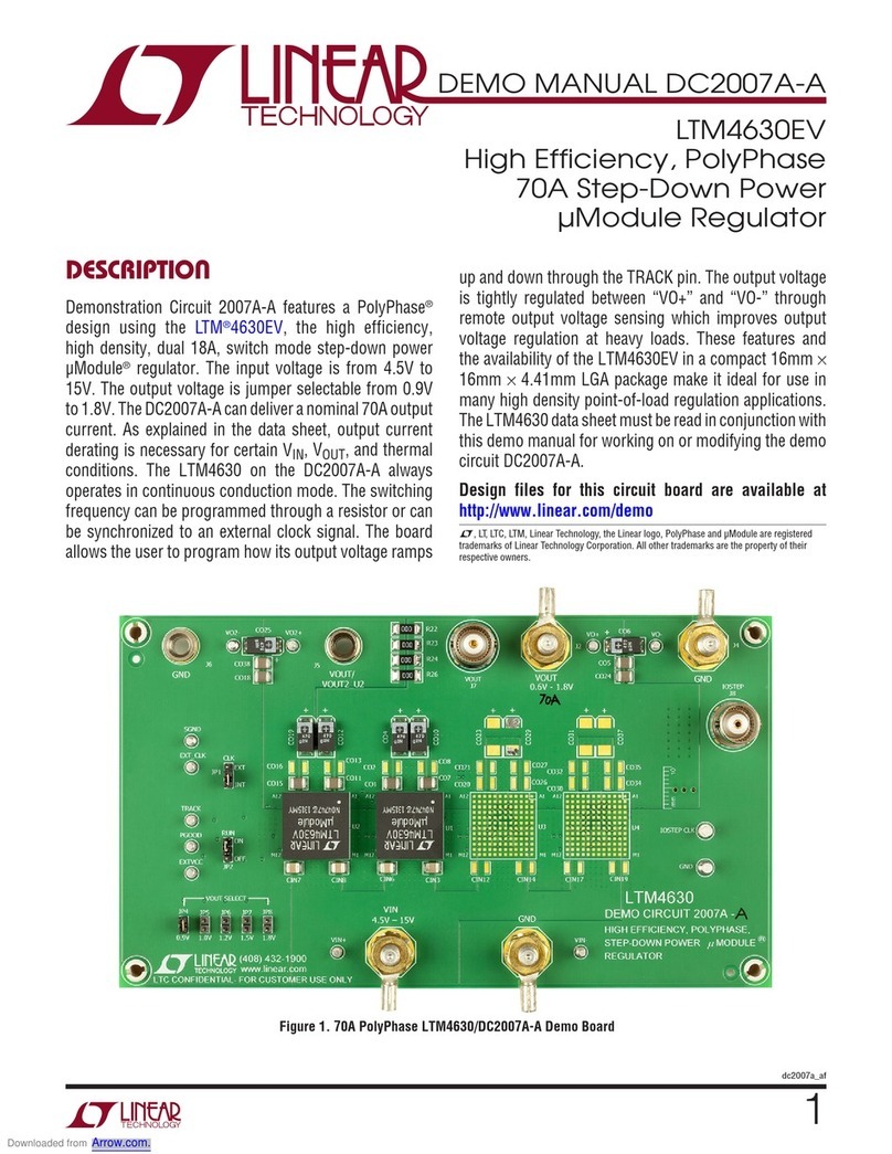
Linear Technology DC2007A-A Quick setup guide
Linear Technology

Linear Technology DC2007A-A Quick setup guide

Linear Technology DC2603A-A Quick setup guide

Linear Technology

Linear Technology DC2603A-A Quick setup guide

Linear Technology DC1496C Quick setup guide

Linear Technology

Linear Technology DC1496C Quick setup guide

Popular Motherboard manuals by other brands
Microchip Technology EVB-LAN9252-PICtail user guide

Microchip Technology

Microchip Technology EVB-LAN9252-PICtail user guide

Vishay SiC413 user manual

Vishay

Vishay SiC413 user manual

Asus P10S-I manual

Asus

Asus P10S-I manual

Asus A85XM-A user manual

Asus

Asus A85XM-A user manual

Samsung AlphaPC 164UX user manual

Samsung

Samsung AlphaPC 164UX user manual

Asus H61M-E user manual

Asus

Asus H61M-E user manual

ECS P4S5A manual

ECS

ECS P4S5A manual

MSI 694D Pro2 manual

MSI

MSI 694D Pro2 manual

Epson S5U13L01P00C100 user manual

Epson

Epson S5U13L01P00C100 user manual

Everspin MR10Q010-EVAL1 user guide

Everspin

Everspin MR10Q010-EVAL1 user guide

Asus PRIME B560M-K manual

Asus

Asus PRIME B560M-K manual

ON Semiconductor NCP1096GEVB user manual

ON Semiconductor

ON Semiconductor NCP1096GEVB user manual

ECS A75F2-M2 user manual

ECS

ECS A75F2-M2 user manual

EPOX EP-D3VA user manual

EPOX

EPOX EP-D3VA user manual

Microchip Technology ATBTLC1000 Series user guide

Microchip Technology

Microchip Technology ATBTLC1000 Series user guide

JETWAY 614DFR1A user manual

JETWAY

JETWAY 614DFR1A user manual

AvaLAN AW900mTR-EVAL user manual

AvaLAN

AvaLAN AW900mTR-EVAL user manual

WONDOM ICP1 How to set up

WONDOM

WONDOM ICP1 How to set up

manuals.online logo
manuals.online logoBrands
  • About & Mission
  • Contact us
  • Privacy Policy
  • Terms and Conditions

Copyright 2025 Manuals.Online. All Rights Reserved.