Linear 2GIG-DW10-345 User manual

Copyright © 2014 Linear LLC 1
2GIG-DW10-345
THIN DOOR/WINDOW CONTACT
INSTALLATION INSTRUCTIONS
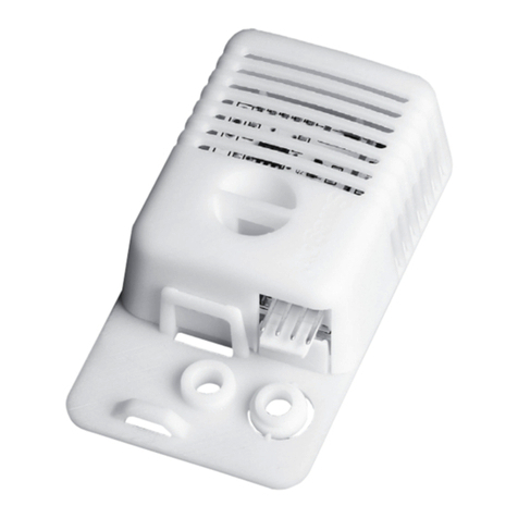
TheThinDoor/WindowContact(2GIG‐DW10‐345)isdesignedforuse
ondoors,windows,andotherobjectsthatopenandclose.It
communicateswiththecontrolpanelusingthe345MHzfrequency.
Whenthemagnet(whichismountednearthesensor)movesaway
fromorclosertothedoorcontact’ssensor,signalsaretransmittedto
thecontrolpanel.Thedoorcontactalsohasanexternalinputthat
acceptsconnectionsfromNormally‐Closed(NC)drycontactdevices.
Foraddedprotection,itisalsoequippedwithacovertamper.
Figure 1 ThinDoor/WindowContact—SensorandMagnet
Box Contents
Verifythatthepackageincludesthefollowing:
•1—ThinDoor/WindowContact
•1—RareEarthMagnet
• 2—PhillipsHeadScrews
• 2—LithiumCoinBatteries
•2—AdhesiveFoamTape
•1—12in(30cm)WireLead
Testing the Thin Door/Window Contact
Beforemountingthedoorcontactatthedesiredlocation,performa
walktesttoverifythatitcanestablishgoodRadioFrequency(RF)
communicationswiththecontrolpanel.
NOTE: TofullytesttheThinDoor/WindowContact,seethe
controlpanel’sInstallationandProgrammingGuide.
Mounting Guidelines
Usetheseguidelineswheninstallingthedoorcontactforinternal
switchusage:
•MountSensorswithin100ft(30m)oftheControlPanel.
Althoughthetransmittermayhavearangeof350ft(106.7m)
openair,thesensorlocationcanhaveasignificanteffecton
range.Inopen/unobstructedsituations,thetransmitterrange
maybegreater.Inadversewirelessconditions,changingthe
sensororientationmayleadtoimprovedrange.
•MountSensorsatLeast4.7in(12cm)AbovetheFloor.
Placingsensorsslightlyabovefloorlevelhelpstominimize
possiblesensordamage.
•Singlevs.DoubleDoorInstallation.Forsingle‐door
installation,mountthesensoronthedoorframeandthe
magnetonthedoor.Fordouble‐doorinstallation,mountthe
sensorontheleast‐useddoorandthemagnetonthemost‐
useddoor.
•DoNotExposeSensorstoMoistureorExtremeTemperature.
Itisbesttomountsensorsinadrylocationwherethe
operatingtemperaturedonotexceed32°to120°F(0°to49°
C).
•KeepSensorsandMagnetsAwayfromMetal/Metallic
Surfaces.Tokeepsensorsandmagnetsawayfrommetalor
metallicsurfaces(forexample,foilwallpaper),itis
recommendedthatyouusespacers(notincluded).Youshould
alsoavoidmountingsensorsinareaswherethereisalarge
quantityofmetalorelectricalwiring(forexample,neara
furnaceorinautilityroom).
•AlignMagnetwithSensor.Makesurethealignmentarrowon
themagnetpointstothecenteralignmentmarkonthesensor
(seeFigure1ThinDoor/WindowContact—Sensorand
Magnet).
Mounting the Thin Door/Window Contact
Usethefigurebelowasaguidelinewhenmountingthedoorcontact.
Instep7below,youhavetheoptiontomountthedoorcontactwith
anexternalinputwireforanNCdrycontactdevice.
Figure 2 ThinDoor/WindowContact—BackplateandBatteryCompartment
Tomountthedoorcontact:
1Atthetopofthesensor,pressdownonthecliptounlockthe
sensor’sbackplate.Then,gentlypulldownonthebackplateto
removeit.
2Onthebackplate,drill‐throughtopandbottommountingholesif
needed(seeFigure2ThinDoor/WindowContact—Backplateand
BatteryCompartment).
3Holdingthebackplatelocation,placethebottommountinghole
asfollows:
•SingleDoorInstallation.Atthedesiredlocationonthedoor
frame.
•DoubleDoorInstallation.Atthedesiredlocationontheleast‐
useddoor.
AThinDoor/WindowContactSensor
BThinDoor/WindowContactMagnet
CAlignmentMarksonSensor
DAlignmentArrowonMagnet
AAccessholeforexternalinputwire(onbackplate)
BTopandbottommountingholes(onbackplate)
CExternalinputwirejack(onsensor)
DTamperswitch(onsensor)
E3‐Volt(3V)lithiumcoinbatterycompartments(onsensor)
FMetalclipsforremovingbatteries(onsensor)

2Copyright © 2014 Linear LLC
Thin Door/Window Contact | Installation Instructions
IMPORTANT: Tominimizetheriskofpotentialsensordamage,
alwaysmountthesensorataminimumheightof4.7in(12
cm)fromthefloor.
4Usingthetwo(2)PhillipHeadScrews(provided),securethe
backplatethedoor(ordoorframe).
5Ensurethatthealignmentarrowonthemagnetislinedupwith
themiddlemarkonthesensor(seeFigure1ThinDoor/
WindowContact—SensorandMagnet).
6Usetheadhesive(provided)tosecurethemagnetasfollows:
•SingleDoorInstallation.Onthedoor.
•DoubleDoorInstallation.Onthemost‐useddoor.
IMPORTANT: Themagnetmustbenomorethan0.4in(1cm)
awayfromthesensor.
NOTE: Ifyouarenotusinganexternalinputwire,skipstep7
andcontinuewithstep8.
7Ifyouareusinganexternalinputwire,dothefollowing:
7a Threadtheexternalinputwirethroughthebase.
7b Insertthetwo‐pinconnectorintotheexternalinputwire
jackonthe(seePartCinFigure2ThinDoor/Window
Contact—BackplateandBatteryCompartment)cover.
8Replacethesensorbackplate.Ifapplicable,ensurethatthe
externalinputwireisconnectedtotheNCdrycontactdevice.
NOTE: TolearnhowtoprogramasensorintotheControlPanel,
seetheControlPanel’sInstallation&ProgrammingGuide.
Inserting and Replacing the Batteries
Toinsertorreplacethebatteries:
1Atthetopofthesensor,pushdownthecliptounlockthe
sensor’sbackplate.Then,gentlypulldownonthebackplateto
removeit.
2Placeasmallflatheadscrewdriverintheslotbetweenthemetal
clipandbattery(seePartFinFigure2ThinDoor/Window
Contact—BackplateandBatteryCompartment).
3Holdingdowntheraisedplasticedgeinthebattery
compartment,gentlytwistthescrewdrivertopopouteach
battery.
IMPORTANT: Alwaysdisposeand/orrecycleusedbatteriesin
accordancewiththehazardouswasterecoveryand
recyclingregulationsforyourlocation.Yourcity,state,or
countrymayalsorequireyoutocomplywithadditional
handling,recycling,anddisposalrequirements.
4Insertthereplacementbatteriesinthecompartment.Theplus
(+)signofbothbatteriesshouldbefacingupandtheminus(‐)
sidefacingdown.
WARNING: Failuretofollowthesewarningsandinstructions
canleadtoheatgeneration,rupture,leakage,explosion,
fire,orotherinjury,ordamage.Donotinsertthebattery
intothecompartmentinthewrongdirection.Always
replacethebatterywiththesameorequivalenttype(see
Specificationsonpage2).Neverrechargeordisassemble
thebattery.Neverplacethebatteryinfireorwater.Always
keepbatteriesawayfromsmallchildren.Ifbatteriesare
swallowed,promptlyseeadoctor.
SPECIFICATIONS
WirelessSignalRange 350ft(106.7m),openair,withWireless
ControlPanel
CodeOutputs Alarm;AlarmRestore;Supervisory;Low
Battery;ExternalAlarm;ExternalRestore;
Tamper;TamperRestore
TransmitterFrequency 345.00MHz(crystalcontrolled)
UniqueIDCodes Overone(1)milliondifferentcode
combinations
SupervisoryInterval 70minutes
ExternalInput AcceptsN/Cdrycontactdevices
MagnetDimensions(LxWxH) 1.3x0.435x0.312in(3.3x1.1x0.79cm)
MagnetType RareEarth
SensorDimensions(DxH) 2.59x1.03x0.49in(6.58x2.62x1.24cm)
Weight(includingbattery&magnet) 1.1oz(31.2g)
HousingMaterial ABSPlastic
Color White
OperatingTemperature 32°‐120°F(0°‐49°C)
RelativeHumidity 5‐90%Non‐Condensing
Battery(included) Two(2)CR2013orequivalentLithium
batteries
Certification Anatel,ETL,FCC,IC,andNOM
REGULATORY INFORMATION
FCC Notice
ThisdevicecomplieswithPart15oftheFCC'sRules.Operationis
subjecttothefollowingtwoconditions:
1Thisdevicemaynotcauseharmfulinterference,and
2Thisdevicemustacceptanyinterferencereceived,including
interferencethatmaycauseundesiredoperation.
Thisequipmenthasbeentestedandfoundtocomplywiththelimits
foraClassBdigitaldevice,pursuanttoPart15oftheFCCRules.
Theselimitsaredesignedtoprovidereasonableprotectionagainst
harmfulinterferenceinaresidentialinstallation.
Thisequipmentgenerates,usesandcanradiateradiofrequency
energyand,ifnotinstalledandusedinaccordancewiththe
instructions,maycauseharmfulinterferencetoradio
communications.However,thereisnoguaranteethatinterference
willnotoccurinaparticularinstallation.Ifthisequipmentdoes
causeharmfulinterferencetoradioortelevisionreception,which
canbedeterminedbyturningtheequipmentoffandon,theuseris
encouragedtotrytocorrecttheinterferencebyoneormoreofthe
followingmeasures:
•Reorientorrelocatethereceivingantenna.
•Increasetheseparationbetweentheequipmentand
receiver.
• Connecttheequipmentintoanoutletonacircuitdifferent
fromthattowhichthereceiverisconnected.
•Consultthedealeroranexperiencedradio/TVtechnicianfor
help.

Copyright © 2014 Linear LLC 3
ThisproductcomplieswithFCCradiationexposurelimitsforan
uncontrolledenvironment.Avoidoperatingthisproductatadistance
lessthan20cmfromtheuser.
CAUTION: Anychangedormodificationsnotexpresslyapproved
bythepartyresponsibleforcompliancecouldvoidtheuser's
authoritytooperatethisequipment.
Industry Canada (IC) Compliance
ThisdevicecomplieswithIndustryCanadalicense‐exemptRSS
standard(s).Operationissubjecttothefollowingtwoconditions:(1)
thisdevicemaynotcauseinterference,and(2)thisdevicemustaccept
anyinterference,includinginterferencethatmaycauseundesired
operationofthedevice.
Repairstocertifiedequipmentshouldbemadebyanauthorized
Canadianmaintenancefacilitydesignatedbythesupplier.Anyrepairs
oralterationsmadebytheusertothisequipment,orequipment
malfunctions,maygivethetelecommunicationscompanycauseto
requesttheusertodisconnecttheequipment.
Usersshouldensurefortheirownprotectionthattheelectrical
groundconnectionsofthepowerutility,telephonelinesandinternal
metallicwaterpipesystem,ifpresent,areconnectedtogether.This
precautionmaybeparticularlyimportantinruralareas.
Usersshouldnotattempttomakesuchconnectionsthemselves,but
shouldcontacttheappropriateelectricinspectionauthority,or
electrician,asappropriate.
LIMITED WARRANTY
ThisLinearproductiswarrantedagainstdefectsinmaterialand
workmanshipfortwo(2)years.Thiswarrantyextendsonlyto
wholesalecustomerswhobuydirectfromLinearLLCorthrough
LinearLLC’snormaldistributionchannels.LinearLLCdoesnotwarrant
thisproducttoconsumers.Consumersshouldinquirefromtheir
sellingdealerastothenatureofthedealer’swarranty,ifany.
TherearenoobligationsorliabilitiesonthepartofLinearLLCfor
consequentialdamagesarisingoutoforinconnectionwithuseor
performanceofthisproductorotherindirectdamageswithrespectto
lossofproperty,revenue,orprofit,orcostofremoval,installation,or
reinstallation.Allimpliedwarrantiesforfunctionality,arevalidonly
untilthewarrantyexpires.ThisLinearLLCWarrantyisinlieuofall
otherwarrantiesexpressedorimplied.
2GIGbyLinear
1950CaminoVidaRoble,Suite150
Carlsbad,CA92008USA
FortechnicalsupportintheUSAandCanada:
855‐2GIG‐TECH(855‐244‐4832)
Email:2gigtechsupport@linearcorp.com
Visitwebsitefortechnicalsupporthoursofoperation
FortechnicalsupportoutsideoftheUSAandCanada:
Contactyourregionaldistributor
Visitdealer.2gig.comforalistofdistributorsinyourregion
77‐000015‐001Rev.B
Other Linear Accessories manuals
Popular Accessories manuals by other brands
Swegon
Swegon CASA Smart Sensor SRH Installation instruction

vidaXL
vidaXL 141466 Operating and safety instructions

Veris
Veris TW Series installation guide
PCB Piezotronics
PCB Piezotronics 350B50/NC Installation and operating manual
fafnir
fafnir TORRIX XTS Series Technical documentation

El-Björn
El-Björn EBL Boj 48/20 LW manual
Elko
Elko inels RFDSC-71 quick start guide
S+S Regeltechnik
S+S Regeltechnik AERASGARD FSLQ Operating Instructions, Mounting & Installation
Preco
Preco S Series Assembly and operational manual

Lanaform
Lanaform Aroma Spring Instructions for use
CombiSteel
CombiSteel 7464.03 Series user manual
Stirling
Stirling AD90G quick start guide
