Benewake TF03 User manual

TF03 RS232-RS485 Product Manual V1.1
Benewake(Beijing)Co., Ltd
Page2
Specified Product
Product model: TF03 RS485-RS232
Product Name: Long-Distance LiDAR
Manufacturer
Company name: Benewake(Beijing) Co., Ltd.
Address: NO.28 Xinxi Road, Haidian District, Beijing, PRC
Copyright
The Copyright of this document is protected. All the rights involved herein belong to
Benewake (Beijing) Co., Ltd. Any copy activity of this document, no matter in whole or in part,
should be in conformity of the Copyright Law. The actives of modification, omission or translation
of this document are not allowed unless a written permission from Benewake (Beijing) Co., Ltd.
All rights reserved © Benewake (Beijing) Co., Ltd.

TF03 RS232-RS485 Product Manual V1.1
Benewake(Beijing)Co., Ltd
Page3
Foreword
Dear users:
Thanks for choosing Benewake products, and it’s our pleasure to help you to solve any
technical question.
For the purpose of offering a better operation experience to you, we hereby write this manual
for an easier and simpler operation of our product, hoping to better solve the common problems
you maybe meet. Please contact us if you have any questions.( bw@benewake.com)
This operation manual covers the product operation introduction and common problem
solutions, but it is really hard to cover all the problems you maybe meet. So if you have any further
questions or problems, please feel free to consult our technical support service
(support@benewake.com). We will do our best to solve any problem related to the product. If you
have any other good advice or suggestions, welcome to visit our official website and offer us your
feedback there (http://en.benewake.com/contact_us), and we are looking forwards to your
participation.
We are Benewake who dedicated to making the best “Robotic Eyes” worldwide!

TF03 RS232-RS485 Product Manual V1.1
Benewake(Beijing)Co., Ltd
Page4
目录
1ATTENTIONS ............................................................................................................................................ 6
1.1 ABOUT THIS DOCUMENT ............................................................................................................................ 6
1.2 USAGE OF PRODUCT.................................................................................................................................. 6
1.3 CONDITIONS WITH POTENTIAL PRODUCT FAILURE ........................................................................................... 6
2PHYSICAL INTERFACE ............................................................................................................................... 7
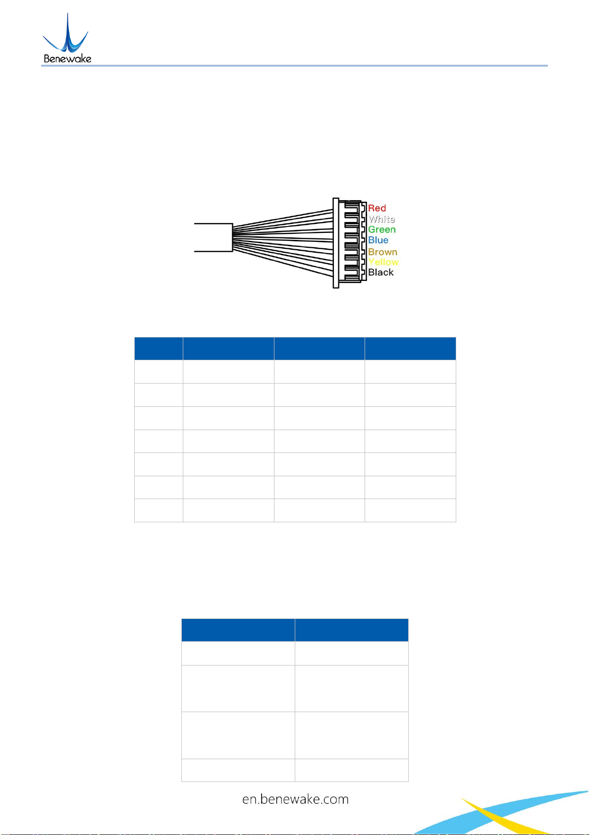
2.1 DESCRIPTION ABOUT THE LINE SEQUENCE AND CONNECTION.............................................................................. 7
2.2 ELECTRICAL CHARACTERISTICS...................................................................................................................... 7
3INSTALLATION INSTRUCTIONS ................................................................................................................. 8
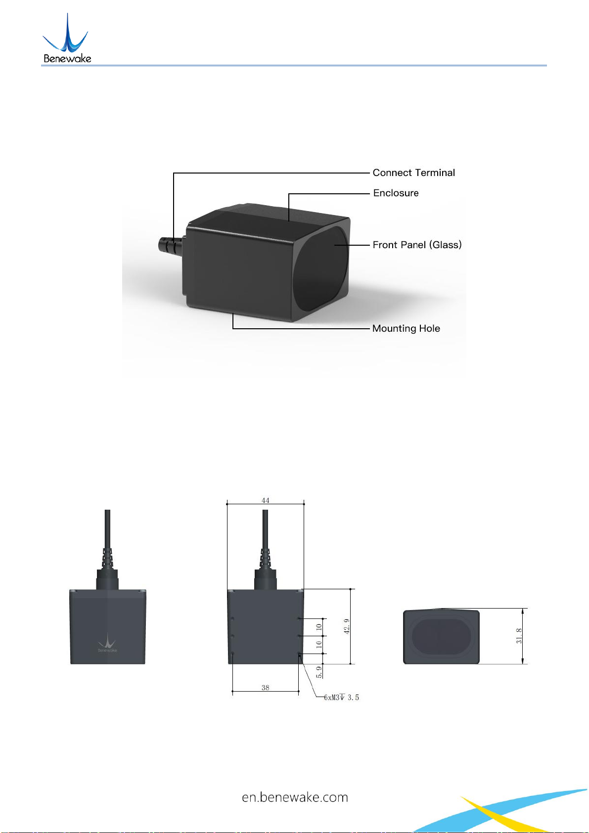
3.1 PRODUCT OVERVIEW................................................................................................................................. 8
3.2 PRODUCT STRUCTURE................................................................................................................................ 8
3.3 DETECTION ANGLE DESCRIPTIONS ................................................................................................................. 9
4COMMUNICATION PROTOCOL AND DATA FORMAT ............................................................................... 10
4.1 COMMUNICATION PROTOCOL .................................................................................................................... 10
4.2 CUSTOMER PARAMETER CONFIGURATIONS ................................................................................................... 11
4.2.1 THE GENERAL FORMAT DESCRIPTION OF COMMANDS................................................................................... 11
4.2.2 COMMANDS ........................................................................................................................................ 12
5QUICK TEST PROCEDURES...................................................................................................................... 13
5.1 REQUIRED TOOLS OF PRODUCT TEST........................................................................................................... 13
5.2 TEST PROCEDURES................................................................................................................................... 14
5.3 TEST EXAMPLE........................................................................................................................................ 15
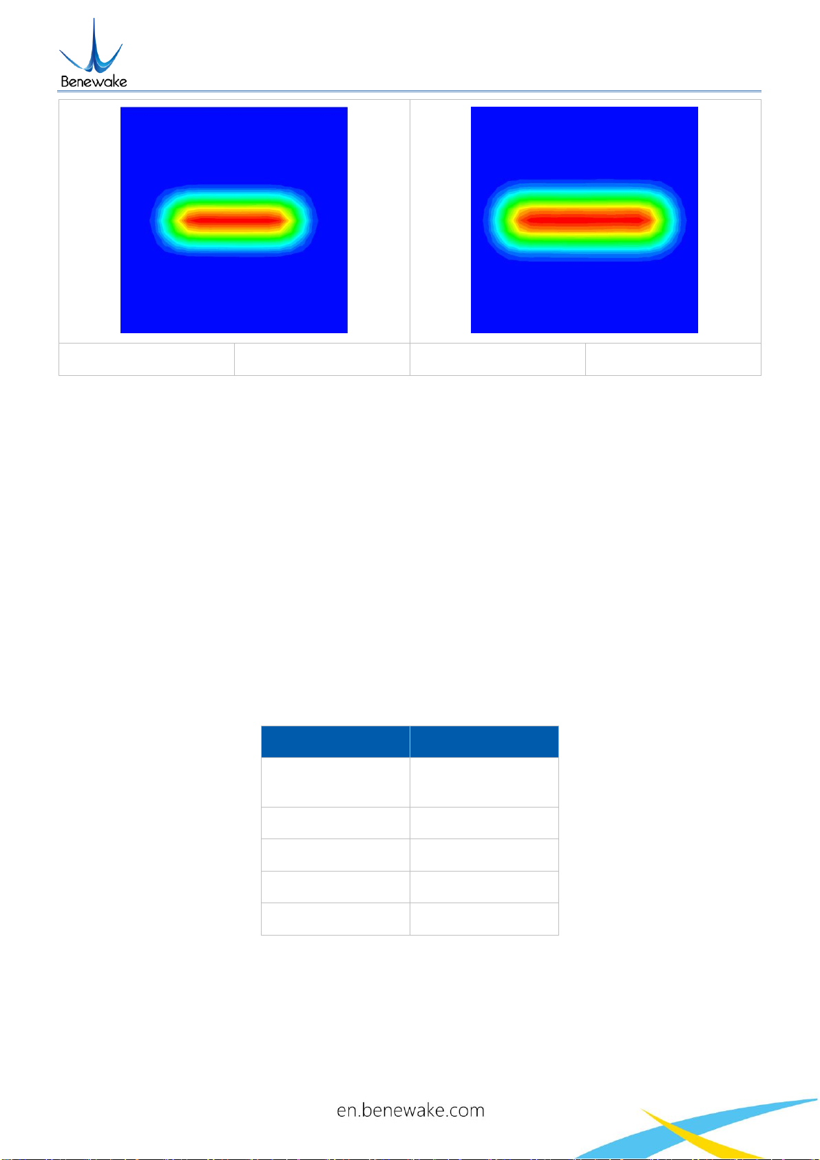
5.3.1 TEST RANGE WITH DIFFERENT REFLECTIVITY................................................................................................ 15
5.3.2 TESTING ACCURACY OF DIFFERENT MATERIALS............................................................................................ 15

TF03 RS232-RS485 Product Manual V1.1
Benewake(Beijing)Co., Ltd
Page5
5.3.3 REFLECTIVITY OF COMMON MATERIALS ..................................................................................................... 16
6TF03 SOFTWARE SETUP ......................................................................................................................... 18
7FAILURE REASONS AND TROUBLESHOOTING......................................................................................... 19
8FREQUENTLY ASKED QUESTIONS ........................................................................................................... 20
ATTACHMENT 1: INSTRUCTION OF TF SERIES PC DISPLAY SOFTWARE ......................................................... 21

TF03 RS232-RS485 Product Manual V1.1
Benewake(Beijing)Co., Ltd
Page6
1Attentions
1.1 About this Document
This Manual provides information necessary for the use of this product.
Please read this Manual carefully before using this product and make sure that you have
fully understood its contents.
1.2 Usage of Product
This product can only be maintained by qualified professionals and only the original spare
parts can be used to ensure its performance and safety.
The product itself has no polarity and overvoltage protection. Please complete wiring and
supply power correctly according to the contents of the Manual.
The working temperature of the product is -25°C~60°C; please do not use it beyond this
temperature range, so as to avoid risks.
The storage temperature of the product is -40°C~85°C; please do not store it beyond this
temperature range, so as to avoid risks.
Do not open its enclosure for assembly or maintenance beyond this Manual; otherwise,
it will affect the product performance.
1.3 Conditions with Potential Product Failure
When the product transmitter and receiver lens are covered by dirt, there will be a risk of
failures. Please keep the lens clean.
The product will have a risk of failure when immersed completely in water. Do not use it
underwater.
When detecting objects with high reflectivity, such as mirrors and smooth tiles, the
product may have a high risk of failures.

TF03 RS232-RS485 Product Manual V1.1
Benewake(Beijing)Co., Ltd
Page7
2 Physical Interface
2.1 Description about the line sequence and connection
Wiring terminal model: MH1.25-7P, core wire: AWG30, diameter:0.254mm, cross-sectional
area:0.05mm2.
Figure 1 TF03 Line Sequence
Table 1 TF03 Pin functions and connection instructions
No
color
Pin
Function
1
Red
VCC
Voltage Input
2
White
485-B
485
3
Green
485-A
485
4
Blue
/
/
5
brown
232_RXD
receiver
6
Yellow
232_TXD
transmitter
7
Black
GND
GND
2.2 Electrical Characteristics
This product has no overvoltage or polarity protection. Please ensure that the wiring and
power supply are normal.
Table 2 main electrical parameters
Parameter
Typical value
Power supply voltage
6-24V
Average current
≤200mA @ 6V
≤100mA @ 12V
≤50mA @ 24V
Peak current
≤200mA @ 6V
≤100mA @ 12V
≤50mA @ 24V
Average power
≤1.2W

TF03 RS232-RS485 Product Manual V1.1
Benewake(Beijing)Co., Ltd
Page8
3 Installation Instructions
3.1 Product Overview
Figure 2 Exterior
3.2 Product Structure
The LiDAR mounting holes are applicable to M3 screws. Note that the length of the screw
entering the enclosure shall be no more than 3.5mm.
Figure 2 TF03 dimensions (Left 1: top view; Left 2: vertical view; Left 3: front view)

TF03 RS232-RS485 Product Manual V1.1
Benewake(Beijing)Co., Ltd
Page9
3.3 Detection angle descriptions
TF03 has a 0.5-degree detection angle and rectangular light spots; see Table 3 for
simulated diagrams of the light spots. Therefore, at different distances, the spot size, namely
detecting range, is different as shown in Figure 4.
Note: The side length of common objects detected should be greater than that of the detection
range of TF03; When the side length of the detected object is less than that of the detection range,
the LiDAR effective range will be reduced
Figure 3 Detection angle schematic of TF03
Table 3 Spot simulated diagrams and sizes at different distances
Spot 20m away
Size:20cm*6cm
Spot 50m away
Size:50cm*14cm

TF03 RS232-RS485 Product Manual V1.1
Benewake(Beijing)Co., Ltd
Page10
Spot 100m away
Size:100cm*28cm
Spot 150m away
Size:150cm*42cm
Note: In it, the red is the strongest, the green is weak, and the dark blue is the background,
and the spot size is the length and width of the green in the figure.
4 Communication protocol and Data format
The TF03 RS485/RS232 version supports RS485 and RS232 communication modes. By
default, both interfaces can communicate, so long as the corresponding interface lines are
connected, they can be used.
4.1 Communication protocol
The communication protocol of TF03 RS485/RS232 is the same as that of UART. TF03
RS232-RS485 communication protocol is shown in Table 4.
Table 4 TF03 Serial port communication protocol
Item
Content
Communication
protocol
RS232-RS485
Baud rate
115200
Data bit
8
Stop bit
1
Checksum bit
None
1)Standard data output format of Serial port(RS485、RS232)
The output data (hexadecimal numbers) of TF03 is shown in table 5. Each data frame
consists of 9 bytes and the data contains the measured distance information; namely, DIST; the
frame tail acts as a data checksum bit; other bytes are reserved.

TF03 RS232-RS485 Product Manual V1.1
Benewake(Beijing)Co., Ltd
Page11
Table 5 TF03 serial data format
Data bit
Definition
Description
Byte0
Frame header
0x59
Byte1
Frame header
0x59
Byte2
DIST_L
DIST low 8-bits
Byte3
DIST_H
DIST high 8-bits
Byte4
Reserved bit
/
Byte5
Reserved bit
/
Byte6
Reserved bit
/
Byte7
Reserved bit
/
Byte8
Checksum
Low 8 bits of Checksum bit. Checksum = Byte0 +
Byte2+…+Byte7
4.2 Customer parameter configurations
4.2.1 The General Format Description of Commands
Custom parameters configurations are open in order that problems could be solved
conveniently. Parameters, such as output data format, output frame rate could be changed by
sending command. Parameter will be stored in flash and needn’t to be configured again if restart
after configured successfully.
Please change the configuration according to the real demands and never try uncorrelated
command frequently thus unnecessary loss from wrong command; please configure the product
according to the demands of the manual and never send unstated command.
The Format of Command is:
Byte
byte0
byte1
byte2
byte3~ byteN-2
byteN-1
Descriptions
Head
Len
ID
Payload
Check sum
Head:fixed to 0x5A
Len:the length of the entire instruction frame (unit: Byte)
ID:identifies the function of each instruction
Payload:have different meanings and lengths in different ID instruction frames

TF03 RS232-RS485 Product Manual V1.1
Benewake(Beijing)Co., Ltd
Page12
Check sum:the lower 8 bits of the Len-1 byte data.
4.2.2 Commands
Function
Command
Response
Remark
Default
setting
Obtaining
version number
5A 04 01 5F
5A 07 01 V1 V2 V3 SU
the version number
V3.V2.V1
SU is check sum,the
same below
/
System reset
5A 04 02 60
success:5A 05 02 00 61
fail:there isn’t any
reaction over 1s
/
/
Frame rate
5A 06 03 LL HH SU
success:is same as
command
fail:there isn’t any
reaction over 1s
/
100fps
Output enabling
switch
enable:5A 05 07 01
67
disable:5A 05 07 00
66
success:is same as
command
fail:there isn’t any
reaction over 1s
/
enabled
Single trigger
instruction
5A 04 04 62
Data frame
/
/
Setting output
format
5A 05 05 LL SU
success:is same as
command
fail:there isn’t any
reaction over 1s
LL:format,
06:RS485 output
RS485
output
Frame rate
5A 08 06 H1 H2 H3 H4
SU
success:is same as
command
fail:there isn’t any
reaction over 1s
Frame rate = (H4 <<
24)+(H3 << 16)+(H2 <<
8)+H1
115200
Enabling
checksum
switch
enable:5A 05 08 01
68
disable:5A 05 08 00
67
success:is same as
command
fail:there isn’t any
reaction over 1s
/
enable
Restoring
factory settings
5A 04 10 6E
success:5A 05 10 00 6F
fail:5A 05 10 ER SU
Fail(when ER is not 0)
/
Save settings
5A 04 11 6F
success:5A 05 11 00 70
fail:5A 05 11 ER SU
same as above
/
Configuring
over range
threshold value
5A 06 4F LL HH SU
success:5A 05 4F 00 AE
fail:there isn’t any
reaction over 1s
over range threshold value
=(HH << 8) + LL,unit cm
18000
Enabling rain-
fog algorithm
enable:5A 05 64 00
C3
disable:5A 05 64 01
C4
success:5A 05 64 00 C3
fail:there isn’t any
reaction over 1s
/
enable

TF03 RS232-RS485 Product Manual V1.1
Benewake(Beijing)Co., Ltd
Page13
Configuring
offset
5A 06 69 LL HH SU
success:5A 05 69 00 C8
fail:there isn’t any
reaction over 1s
Offset = (HH << 8) + LL,
unit cm
0
Interpretation:
1) The supported output frame rate is as follows:
1、2、…9、
10、20、…90、
100、200…900、
1000、2000…9000、10000;
2) When using the trigger mode, you need to disable data output, and then use the trigger
command;
3) “Configuring offset”can be used for customer secondary calibration radar distance,
supported from firmware version v1.11.3.
5 Quick Test Procedures
5.1 Required Tools of Product Test
Note: the product package contains only TF03 products and factory certificate, and other
accessories are collected by yourself.
The version of TF03-RS485 connected to the computer needs to use 485-USB board, the
version of TF03-RS232 connected to the computer need to use 232-USB board, please pay
attention to different versions of the line sequence when connecting. the following example
represents the serial port version TF03 connected to the computer tools and methods.
TF03
(232/485)
232/485 -
USB Board
USB Cable
PC
TF display
program
Figure 4 Tools example

TF03 RS232-RS485 Product Manual V1.1
Benewake(Beijing)Co., Ltd
Page14
5.2 Test procedures
1)Download the TF display program
Please download the TF display program from http://benewake.com/en/down.html
Note: Please close the anti-virus software before unpacking the TF display program;
otherwise, the files in the TF display program will be deleted as viruses; The TF display program
currently only supports running on the Windows system. See Attachment 1: Instruction of TF
Series PC Display Software.
Figure 5 How to connect TF03 to PC for test
As figure 6 shown, connect 『TF03』->『232/485 - USB board』->『USB cable』, ensure
no looseness, and then connect the 『USB cable』with the『computer』.
3)TF display software connection and reading
Figure 6 The interface of TF display software
As shown in Figure 7, open the TF display program, selectⅠ『Benewake TF03』 and select
the serial port for automatic identification (here is Ⅱ『COM9』).

TF03 RS232-RS485 Product Manual V1.1
Benewake(Beijing)Co., Ltd
Page15
Then, click『CONNECT』to connect to the TF display program.
After connected successfully, continuous output data images will occur in the right Ⅳ『TIME
LINE CHART』area and the Ⅴ『REAL TIME DATA』area below will display the current test
distance (Dist: 125cm), the output frame rate (Effective Points: 100Hz).
Note: the Dist(Echo) and Strength are unmeaning in here.
4)Another note
If TF03 is required to output in Pixhawk mode, check Ⅲ『Pix Mode』 first and then the data
images will be normally output in the Ⅳ『 TIME LINE CHART』 area. After the Pix Mode is checked,
the distance unit will change to m.
5.3 Test Example
5.3.1 Test Range with Different Reflectivity
As shown in Figure 8, the 180m version of TF03, red and blue curves represent the
relationship between the reflectance and range of the target under different ambient light
intensities indoors and outdoors, respectively.
Figure 8 The relationship between TF03 range and reflectance (version 180m)
5.3.2 Testing Accuracy of Different Materials
The test accuracy of TF03 at different distances and reflectivity is shown in Figure 9. Two

TF03 RS232-RS485 Product Manual V1.1
Benewake(Beijing)Co., Ltd
Page16
typical background boards(blackboard and whiteboard), are selected. The reflectivity of
whiteboard is 90% and that of blackboard is 10%.
Figure 9 Error curves of TF03 at different distances and reflectivity
5.3.3 Reflectivity of Common Materials
The reflectivity of common materials is listed below, ranging from low to high. According to
the test target and the corresponding reflectivity, we can measure whether the range of TF03 and
other parameters meet the requirements.
No.
Materials
Reflectivity
1
black foam rubber
2.4%
2
black cloth
3%
3
black rubber
4%
4
Coal (varies from coal to coal)
4~8%
5
Black car paint
5%
6
Black paper
10%
7
opaque black plastic
14%
8
Clean rough board
20%

TF03 RS232-RS485 Product Manual V1.1
Benewake(Beijing)Co., Ltd
Page17
9
newspapers
55%
10
translucent plastic bottles
62%
11
packing case cardboard
68%
12
Clean pine
70%
13
opaque white plastic
87%
14
white card
90%
15
Kodak standard whiteboard
100%
16
Unpolished white metal surface
130%
17
Shiny light metal surface
150%
18
stainless steel
200%
19
Reflective board, reflective
adhesive tape
>300%

TF03 RS232-RS485 Product Manual V1.1
Benewake(Beijing)Co., Ltd
Page18
6 TF03 Software Setup
Figure 7 TF03 Setup software display
Interface of custom TF display software is shown in the figure above.
1) After TF03 is connected to the computer, select the correct port number and baud rate in
Zone C manually and click the 『Connect』 button to realize communication between
the TF display software and TF03.
2) After connection is successfully established, zone B will display the ranging distance and
the frequency of data obtained by the TF display software. When no data is received after
two seconds, the data and frequency display will disappear.
3) Zone D is dedicated to function configuration and its third column lists the buttons for
sending instructions. After clicking such buttons, the setup software will send instructions
and wait for reply from TF03. When no reply is received for a long time, 『No Response』
will be displayed on the right side of the instruction-sending buttons. Please note that in
order to ensure that TF03 reply instructions can be obtained normally, lower the『frame

TF03 RS232-RS485 Product Manual V1.1
Benewake(Beijing)Co., Ltd
Page19
rate』or set the『output mode』as『instruction trigger』before configuration. If the changed
parameters need to be saved, click the settings button corresponding to 『Save
Configuration』before power down TF03.
4) Region E is dedicated to firmware upgrade, which enables the BootLoader function to be
used for upgrading the product firmware.
7 Failure reasons and troubleshooting
1)Under normal operation, TF03 sometimes will output 18000(cm).
Reasons:The actual distance measured is beyond the range of TF03, TF03 will output 18000.
Troubleshooting:Use the value 18000 as a value representing abnormal data. In other words,
after value 18000 is received, the TF03 output data is not used.
2)No data output after TF03 is connected to the TF display software.
Reason Ⅰ:The computer uses and operating system other than Windows.
Troubleshooting:Currently, the TF display software can only support the Windows operating
system. Use a computer with the Window operating system installed.
Reason Ⅱ: Poor connection between TF03 and computer.
Troubleshooting : Please confirm that TF03 is correctly and reliably connected to the
computer, and ensure that the cables and adapter board work properly.
3)TF03 does not cover the nominal range in some cases.
Reason: TF03 bases on the time-of-flight (TOF) principle, to achieve ranging by calculating
the round-trip time of flight of laser pulses. The intensity of ambient light or the reflectivity of
objects under testing is different, and thus will increase the intensity of ambient noise or return
light intensity. Therefore, the ranging performance of TF03 varies with different ambient light
intensities and reflectivities.
Troubleshooting: Under different ambient light intensity and reflectivity of objects under
testing, having different ranges is a normal phenomenon and does not affect the accuracy or
repeatability. Therefore, it can be used normally.

TF03 RS232-RS485 Product Manual V1.1
Benewake(Beijing)Co., Ltd
Page20
8 Frequently asked questions
Q1:Can the divergence angle (spot) of TF03 be increased or decreased?
A1: Generally, this is a custom requirement. You need to contact the sales staff for further
details. Divergence angle is determined at the beginning of product design. Determination of
divergence angle is also closely linked to the optical system and the product structure. Therefore,
it cannot be easily changed, and needs to be customized.
Q2: Can TF03 change the frequency of data output? Can TF03 output switching values?
A2: So far, customization of parameter configurations and adjustment of output modes have
been enabled for TF03. However, switching values have to be customized according to
requirements. You may consult our sales staff or technical support for further details.
Q3: Can TF03 work normally in rain, snow and fog?
A3: TF03 has a firmware version of the algorithm that penetrates the rain and fog. Contact
the sales or technical support personnel for firmware upgrade. The algorithm is turned on by
default in V1.11.15.
Other manuals for TF03
6
Table of contents
Other Benewake Accessories manuals

Benewake
Benewake TF02-Pro User manual

Benewake
Benewake CE30-C User manual

Benewake
Benewake TF350 User manual

Benewake
Benewake TF350 User manual

Benewake
Benewake TF03 User manual

Benewake
Benewake TF02-i User manual

Benewake
Benewake TFmini-i User manual

Benewake
Benewake TF02-Pro-W-485 User manual

Benewake
Benewake TF02-Pro-W-485 User manual

Benewake
Benewake TF350-RS-485 User manual