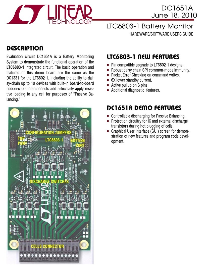
Linear ANALOG DEVICES LTM4680 User manual

LTM4680
1
Rev. B
For more information www.analog.comDocument Feedback
TYPICAL APPLICATION
FEATURES DESCRIPTION
Dual 30A or Single 60A µModule Regulator
with Digital Power System Management
The LTM
®
4680 is a dual 30A or single 60A step-down
µModule
®
(power module) DC/DC regulator featuring
remote configurability and telemetry-monitoring of power
management parameters over PMBus—an open stan-
dard I2C-based digital interface protocol. The LTM4680
is comprised of digitally programmable analog control
loops, precision mixed-signal circuitry, EEPROM, power
MOSFETs, inductors and supporting components.
The LTM4680 product video is available on the website.
The LTM4680’s 2-wire serial interface allows outputs
to be margined, tuned and ramped up and down at pro-
grammable slew rates with sequencing delay times. True
input current sense, output currents and voltages, output
power, temperatures, uptime and peak values are read-
able. Custom configuration of the EEPROM contents is not
required. At start-up, output voltages, switching frequency,
and channel phase angle assignments can be set by pin-
strapping resistors. The LTpowerPlay
®
GUI and DC1613
USB-to-PMBus converter and demo kits are available.
The LTM4680 is offered in a 16mm ×16mm ×7.82mm
BGA package available with SnPb or RoHS compliant ter-
minalfinish. Pin compatible with LTM4678.
APPLICATIONS
n Dual 30A or Single 60A Digitally Adjustable Analog
Loops with Digital Interface for Control and Monitoring
n Wide Input Voltage Range: 4.5V to 16V
n Output Voltage Range: 0.5V to 3.3V
n 90% Full Load Efficiency from 12VIN to 1VOUT at 60A
n ±0.5% Maximum DC Output Error Over Temperature
n ±2.5% Current Readback Accuracy (25°C to 125°C)
n Integrated Input Current Sense Amplifier
n 400kHz PMBus-Compliant I2C Serial Interface
n Supports Telemetry Polling Rates up to 125Hz
n Constant Frequency Current Mode Control
n Parallel and Current Share Multiple Modules
n Pin Compatible with LTM4678
n 16mm ×16mm ×7.82mm BGA Package
Readable Data:
n Input and Output Voltages, Currents, and Temperatures
n Running Peak Values, Uptime, Faults and Warnings
n Onboard EEPROM Fault Log Record
Writable Data and Configurable Parameters:
n Output Voltage, Voltage Sequencing and Margining
n Digital Soft-Start/Stop Ramp, Program Analog Loop
n OV/UV/OT, UVLO, Frequency and Phasing
n System Optimization, Characterization and Data Mining
in Prototype, Production and Field Environments
All registered trademarks and trademarks are the property of their respective owners. Protected
by U.S. Patents including 5408150, 5481178, 5705919, 5929620, 6144194, 6177787, 6580258,
7420359, 8163643. Licensed under U.S. Patent 7000125 and other related patents worldwide.
Dual 30A µModule Regulator with Digital Interface for Control and Monitoring* Efficiency vs Current at 12V Input
1.0V, 250kHz
1.5V, 425kHz
LOAD CURRENT (A)
0
5
10
15
20
25
30
65
70
75
80
85
90
95
100
EFFICIENCY (%)
4680 TA01b
RSENSE
22µF
×5
100µF
×8
100µF
×8
VOSNS0+
VOSNS0–
FAULT0
FAULT1
WP
SYNC
VIN0
VOUT0
SCL
SDA
RUN0
RUN1
VIN1
VOSNS1+
VOUT1
ALERT
SHARE_
CLK
GND
SVIN
VOSNS1–
SGND
IN+
IN–
LTM4680
LOAD0
LOAD1
I2C/SMBus I/F WITH PMBus
COMMAND SET TO/FROM
IPMI OR OTHER BOARD
MANAGEMENT CONTROLLER
4.5V to 16V
(FROM
4.5V TO 5.75V,
CONNECT
VIN, SVIN
AND INTVCC
TOGETHER)
ON/OFF CONTROL
FAULT INTERRUPTS
SYNCHRONIZATION TIME-BASE
REGISTER WRITE PROTECTION
VOUT1
ADJUSTABLE
UP TO 30A
VOUT0
ADJUSTABLE
UP TO 30A
4680 TA01a
*FOR COMPLETE CIRCUIT, SEE FIGURE 46
Click to view associated Video Design Idea.

LTM4680
2
Rev. B
For more information www.analog.com
TABLE OF CONTENTS
Features..................................................... 1
Applications ................................................ 1
Typical Application ........................................ 1
Description.................................................. 1
Table of Contents .......................................... 2
Absolute Maximum Ratings.............................. 4
Order Information.......................................... 4
Pin Configuration .......................................... 4
Electrical Characteristics ................................. 5
Typical Performance Characteristics .................. 12
Pin Functions .............................................. 15
Simplified Block Diagram ............................... 19
Decoupling Requirements............................... 19
Functional Diagram ...................................... 20
Test Circuits ............................................... 21
Operation................................................... 23
Power Module Introduction ...................................23
Power Module Overview, Major Features................23
EEPROM with ECC ................................................. 24
Power-Up and Initialization ....................................25
Soft-Start ...............................................................26
Time-Based Sequencing ........................................26
Voltage-Based Sequencing ....................................26
Shutdown ..............................................................27
Light-Load Current Operation ................................27
Switching Frequency and Phase .............................28
PWM Loop Compensation .....................................28
Output Voltage Sensing .........................................28
INTVCC/EXTVCC Power ..........................................28
Output Current Sensing and Sub Milliohm
DCRCurrent Sensing .............................................29
Input Current Sensing ............................................29
PolyPhase Load Sharing ........................................29
External/Internal Temperature Sense .....................30
RCONFIG (Resistor Configuration) Pins .................30
Table1. VOUTn_CFG Pin Strapping Look-Up Table for
the LTM4680’s Output Voltage, Coarse Setting (Not
Applicable if MFR_CONFIG_ALL[6] = 1b).............31
Table2. VTRIMn_CFG Pin Strapping Look-Up
Table for the LTM4680’s Output Voltage, Fine
Adjustment Setting (Not Applicable if MFR_
CONFIG_ALL[6] = 1b) ........................................31
Table3. FSWPH_CFG Pin Strapping Look-Up Table
to Set the LTM4680’s Switching Frequency and
Channel Phase-Interleaving Angle (Not Applicable
if MFR_CONFIG_ALL[6] = 1b) ...........................32
Table4. ASEL Pin Strapping Look-Up Table to
Set the LTM4680’s Slave Address (Applicable
Regardless of MFR_CONFIG_ALL[6] Setting) ....33
Table5. LTM4680 MFR_ADDRESS Command
Examples Expressed in 7- and 8-Bit Addressing .... 33
Fault Detection and Handling .................................33
Status Registers and ALERT Masking ..................34
Figure5. LTM4680 Status Register Summary......35
Mapping Faults to FAULT Pins .............................36
Power Good Pins .................................................36
CRC Protection ....................................................36
Serial Interface ......................................................36
Communication Protection ..................................36
Device Addressing .................................................36
Responses to VOUT and IIN/IOUT Faults ..................37
Output Overvoltage Fault Response ....................37
Output Undervoltage Response ...........................38
Peak Output Overcurrent Fault Response ............38
Responses to Timing Faults ...................................38
Responses to VIN OV Faults ...................................38
Responses to OT/UT Faults ....................................38
Internal Overtemperature Fault Response ............38
External Overtemperature and
UndertemperatureFaultResponse ....................39
Responses to Input Overcurrent and Output
Undercurrent Faults ...............................................39
Responses to External Faults .................................39
Fault Logging .........................................................39
Bus Timeout Protection .........................................39
Similarity Between PMBus, SMBus and I2C
2-WireInterface .....................................................40
PMBus Serial Digital Interface ...............................40
Table6. Abbreviations of Supported Data Formats ...41
Figure6. PMBus Timing Diagram ......................... 41
Figures 7 to 24 PMBus Protocols ...........................42

LTM4680
3
Rev. B
For more information www.analog.com
TABLE OF CONTENTS
PMBus Command Summary ............................ 45
PMBus Commands ................................................45
Table7. PMBus Commands Summary (Note:
The Data Format Abbreviations Are Detailed in
Table8) ...........................................................45
Table8. Data Format Abbreviations .....................50
Applications Information ................................ 51
VIN to VOUT Step-Down Ratios ............................... 51
Input Capacitors .................................................... 51
Output Capacitors .................................................. 51
Light Load Current Operation ................................. 51
Switching Frequency and Phase ............................52
Output Current Limit Programming .......................53
Minimum On-Time Considerations .........................54
Variable Delay Time, Soft-Start and Output
VoltageRamping ...................................................54
Digital Servo Mode ................................................54
Soft Off (Sequenced Off) .......................................55
Undervoltage Lockout ............................................56
Fault Detection and Handling .................................56
Open-Drain Pins ....................................................56
Phase-Locked Loop and Frequency Synchronization . 57
Input Current Sense Amplifier ................................58
Programmable Loop Compensation ......................58
Checking Transient Response ................................59
PolyPhase Configuration .....................................60
Connecting The USB to I2C/SMBus/PMBus
Controllerto the LTM4680 In System ....................60
LTpowerPlay:An Interactive GUI for Digital Power....... 61
PMBus Communication and Command
Processing .............................................................61
Thermal Considerations and Output
CurrentDerating ..................................................63
Tables 10 thru 11: Output Current Derating...........66
Table12. Channel Output Voltage vs Capacitor
Selection, All Ceramic Configuration, 15A to 30A
Load Step with 15A/µs Slew Rate ......................66
Table13. Channel Output Voltage vs Capacitor
Selection, Bulk and Ceramic Cap Configuration,
15A to 30A Load Step with 15A/µs Slew Rate ...67
Table14. Dual Phase Single Output Voltage vs
Capacitor Selection, Bulk and Ceramic Cap
Configuration, 30A to 60A Load Step with 30A/µs
Slew Rate ..........................................................68
Derating Curves ......................................................69
EMI Performance ...................................................70
Safety Considerations ............................................70
Layout Checklist/Example .....................................70
Typical Applications ...................................... 72
PMBus Command Details ............................... 77
Addressing and Write Protect.................................77
General Configuration Commands..........................79
On/Off/Margin ........................................................80
PWM Configuration ................................................82
Voltage....................................................................85
Input Voltage and Limits.......................................85
Output Voltage and Limits ....................................86
Output Current and Limits ......................................89
Input Current and Limits ......................................91
Temperature............................................................92
Power Stage DCR Temperature Calibration...........92
Timing ....................................................................93
Timing—On Sequence/Ramp...............................93
Timing—Off Sequence/Ramp ..............................94
Precondition for Restart .......................................95
Fault Response .......................................................95
Fault Responses All Faults....................................95
Fault Responses Input Voltage .............................96
Fault Responses Output Voltage...........................96
Fault Responses Output Current...........................99
Fault Responses IC Temperature ........................ 100
Fault Responses External Temperature............... 101
Fault Sharing......................................................... 102
Fault Sharing Propagation .................................. 102
Fault Sharing Response...................................... 104
Scratchpad ........................................................... 104
Identification......................................................... 105
Fault Warning and Status...................................... 106
Telemetry.............................................................. 113
NVM Memory Commands .................................... 117
Store/Restore ..................................................... 117
Fault Logging...................................................... 118
Block Memory Write/Read.................................. 122
Package Description ................................... 123
Table23. LTM4680 BGA Pinout.......................... 123
Revision History ........................................ 125
Package Photograph ................................... 126
Design Resources ...................................... 126
Related Parts ............................................ 126

LTM4680
4
Rev. B
For more information www.analog.com
PIN CONFIGURATIONABSOLUTE MAXIMUM RATINGS
Terminal Voltages:
VINn(Note 4), SVIN, IIN+, IIN−...................... –0.3V to 18V
(SVIN – IIN+), (IIN+– IIN−)........................... –0.3V to 0.3V
SW0, SW1 .................. −1V to 18V, −5V to 18V Transient
INTVCC, EXTVCC........................................... –0.3V to 6V
VOUTn........................................................ –0.3V to 3.6V
VOSNS0+, VOSNS1+......................................... –0.3V to 6V
VOSNS0−, VOSNS1−...................................... –0.3V to 0.3V
RUNn, SDA, SCL, ALERT ........................... –0.3V to 5.5V
FSWPH_CFG, VOUT0,1_CFG,
VTRIM0,1_CFG, ASEL ......................... –0.3V to 2.75V
FAULTn, SYNC, SHARE_CLK, WP,
PGOOD0, PGOOD1 ............................... −0.3V to 3.6V
COMPna, COMPnb, .................................. –0.3V to 2.7V
TSNS0a, TSNS1a...................................... –0.3V to 2.2V
TSNS0b, TSNS1b...................................... –0.3V to 0.8V
Temperatures
Internal Operating Temperature Range
(Notes 2, 13, 16, 17) .............................. –40°C to 125°C
Storage Temperature Range .................. –55°C to 125°C
Peak Solder Reflow Package Body Temperature... 245°C
(Not recommended for upside down reflow.)
(Note 1)
1 2 3 4 5 6 7 8 9 10 11 12
M
L
K
J
H
G
F
E
D
C
B
A
GND
GND
GND
VOUT0
GND
INTVCC VDD33
FSWPH_
CFG
VOUT0_
CFG
SHARE
CLK
VOUT1_
CFG
VTRIM1_
CFG
EXTVCC
GND
RUN1
PGOOD1
PGOOD0
VOSNS0+VOSNS0–
TOP VIEW
BGA PACKAGE
144-LEAD (16mm × 16mm × 7.82mm)
TJMAX = 125°C, θJCtop = 3.3°C/W, θJCbottom = 2°C/W, θJB = 2°C/W, θJA = 7°C/W
WEIGHT = 7.4 GRAMS
GND VOUT0
VOSNS1+VOSNS1–
VOUT1
VOUT1
SGND
VIN0
VIN1
SW0
SW1
SVIN
IIN+
IIN–
VDD25
ASEL
VTRIM0_
CFG
RUN0
FAULT0ALERT
FAULT1
COMP0b SDA
COMP0a
COMP1b
COMP1a
SYNC
SCLTSNS0aTSNS1aTSNS0b
TSNS1b
WP
ORDER INFORMATION
PART NUMBER PAD OR BALL FINISH
PART MARKING* PACKAGE
TYPE
MSL
RATING
TEMPERATURE RANGE
(See Note 2)
DEVICE FINISH CODE
LTM4680EY#PBF SAC305 (RoHS) LTM4680Y e1 BGA 4 –40°C to 125°CLTM4680IY#PBF LTM4680Y
LTM4680IY SnPb (63/37) LTM4680Y e0
Contact the factory for parts specified with wider operating temperature
ranges. *Device temperature grade is indicated by a label on the shipping
container. Pad or ball finish code is per IPC/JEDEC J-STD-609.
• Recommended LGA and BGA PCB Assembly and Manufacturing
Procedures
• LGA and BGA Package and Tray Drawings

LTM4680
5
Rev. B
For more information www.analog.com
ELECTRICAL CHARACTERISTICS
The ldenotes the specifications which apply over the specified internal
operating temperature range (Note 2). nis specified as each individual output channel (Note 4). TA= 25°C, VIN = 12V, RUNn = 3.3V,
EXTVCC=0, FREQUENCY_SWITCH = 350kHz and VOUTncommanded to 1.000V unless otherwise noted. Configured with factory-default
EEPROM settings and per Test Circuit 1, unless otherwise noted.
SYMBOL PARAMETER CONDITIONS MIN TYP MAX UNITS
VIN Input DC Voltage Test Circuit 1
Test Circuit 2; VIN_OFF < VIN_ON = 4V
l
l
5.75
4.5
16
5.75
V
V
VOUTnRange of Output Voltage Regulation VOUTnDifferentially Sensed on VOSNSn+/VOSNSn– Pin-Pair;
Commanded by Serial Bus or with Resistors Present at
Start-Up on VOUTn_CFG
l0.5 3.34 V
VOUTn(DC) Output Voltage, Total Variation with
Line and Load
Digital Servo Engaged (MFR_PWM_MODEn[6] = 1b)
Digital Servo Disengaged (MFR_PWM_MODEn[6] = 0b)
VOUTnCommanded to 1.000V, VOUTnLow Range
(MFR_PWM_MODEn[1] = 1b) (Note 5)
l 0.995
0.985
1.000
1.000
1.005
1.015
V
V
VUVLO Undervoltage Lockout Threshold,
When VIN < 4.3V
VINTVCC Falling
VINTVCC Rising
3.55
3.90
V
V
Input Specifications
IINRUSH(VIN) Input Inrush Current at
Start-Up
Test Circuit 1, VOUTn=1V, VIN = 12V; No Load Besides
Capacitors; TON_RISEn= 3ms (Note 12)
50 mA
IQ(SVIN) Input Supply Bias Current Forced Continuous Mode, MFR_PWM_MODEn[0] = 1b
RUNn= 3.3V
Shutdown, RUN0 = RUN1 = 0V
37
25
mA
mA
IS(VINn,DCM) Input Supply Current in
Discontinuous Mode Operation
Discontinuous Mode, MFR_PWM_MODEn[0] = 0b,
IOUTn= 100mA
20 mA
IS(VINn,FCM) Input Supply Current in Forced-
Continuous Mode Operation
Forced Continuous Mode, MFR_PWM_MODEn[0] = 1b
VINn= 12V, VOUTn= 1V
IOUTn= 30A
3.2
A
Output Specifications
IOUTnOutput Continuous Current Range Utilizing MFR_PWM_MODE[7] = 1 for IOUT_OC_FAULT_
LIMIT, Page 90 (Note 6)
0 30 A
∆VOUTn(LINE)
VOUTn
Line Regulation Accuracy Digital Servo Engaged (MFR_PWM_MODEn[6] = 1b)
Digital Servo Disengaged (MFR_PWM_MODEn[6] = 0b)
SVIN and VINnElectrically Shorted Together and INTVCC
Open Circuit;IOUTn= 0A, 5.75V ≤ VIN ≤ 16V, VOUT Low Range
(MFR_PWM_MODEn[1] = 1b), FREQUENCY_SWITCH =
350kHz (Note 5)
l
0.03
0.03
±0.2
%/V
%/V
∆VOUTn(LOAD)
VOUTn
Load Regulation Accuracy Digital Servo Engaged (MFR_PWM_MODEn[6] = 1b)
Digital Servo Disengaged (MFR_PWM_MODEn[6] = 0b)
0A ≤ IOUTn≤ 30A, VOUTnLow Range, (MFR_PWM_
MODEn[1] = 1b) (Note 5)
l
0.03
0.2
0.5
%
%
VOUTn(AC) Output Voltage Ripple 10 mVP-P
fS(Each Channel) VOUTnRipple Frequency FREQUENCY_SWITCH Set to 350kHz (0xFABC) l320 350 370 kHz
∆VOUTn(START) Turn-On Overshoot TON_RISEn= 3ms (Note 12) 8 mV
tSTART Turn-On Start-Up Time Time from VIN Toggling from 0V to 12V to Rising Edge
PGOODn. TON_DELAYn= 0ms, TON_RISEn= 3ms
l30 ms
tDELAY(0ms) Turn-On Delay Time Time from First Rising Edge of RUNnto Rising Edge of
PGOODn. TON_DELAYn= 0ms, TON_RISEn= 3ms,
VIN Having Been Established for at Least 70ms
l2.75 3.1 3.8 ms
∆VOUTn(LS) Peak Output Voltage Deviation for
Dynamic Load Step
Load: 0A to 15A and 15A to 0A at 15A/µs,
VOUTn= 1V, VIN = 12V (Note 12) See Transient Graph
60 mV
tSETTLE Settling Time for Dynamic Load Step Load: 0A to 15A and 15A to 0A at 15A/µs,
VOUTn= 1V, VIN = 12V (Note 12) See Transient Graphs
50 µs

LTM4680
6
Rev. B
For more information www.analog.com
ELECTRICAL CHARACTERISTICS
The ldenotes the specifications which apply over the specified internal
operating temperature range (Note 2). nis specified as each individual output channel (Note 4). TA= 25°C, VIN = 12V, RUNn= 3.3V,
EXTVCC=0, FREQUENCY_SWITCH = 350kHz and VOUTncommanded to 1.000V unless otherwise noted. Configured with factory-default
EEPROM settings and per Test Circuit 1, unless otherwise noted.
SYMBOL PARAMETER CONDITIONS MIN TYP MAX UNITS
IOUTn(OCL_AVG) Output Current Limit, Time
Averaged, Readback
Time-Averaged Output Inductor Current Limit Inception
Threshold, Commanded by IOUT_OC_FAULT_LIMITn
(Note12)
Utilizing MFR_PWM_MODE[7] = 0, Using IL PEAK = 40A,
Page 90
39 A
Control Section
VFBCMnFeedback Input Common Mode
Range
VOSNSn–Valid Input Range (Referred to SGND)
VOSNSn+Valid Input Range (Referred to SGND)
l
l
–0.1 0.3
3.6
V
V
VOUT-RNGL Full-Scale Command Voltage, Range
Low (0.5V to 2.75V)
Set Point Accuracy
Resolution
LSB Step Size
VOUTnCommanded to 2.750V, MFR_PWM_MODEn[1] = 1b
(Notes7,15)
−0.5
2.75
12
0.688
0.5
V
%
Bits
mV
VOUT-RNGH Full-Scale Command Voltage, Range
High (0.5V to 3.6V)
Set Point Accuracy
Resolution
LSB Step Size
VOUTnCommanded to 3.6V, MFR_PWM_MODEn[1] = 0b
Limit Design to 3.6V Operating for Module
(Notes7,15)
–0.5
3.6
12
1.375
0.5
V
%
Bits
mV
RVSNS0+VOSNS0+Impedance to SGND 0.05V ≤ VVOSNS0+– VSGND ≤ 3.3V 50 kΩ
RVSNS1+VOSNS1+ Impedance to SGND 0.05V ≤ VVOSNS1+– VSGND ≤ 3.3V 50 kΩ
tON(MIN) Minimum On-Time (Note 8 ) 60 ns
RCOMP0,1 Resolution
Compensation Resistor RTH(MAX)
Compensation Resistor RTH(MIN)
MFR_PWM_CONFIG[4:0] = 0 to 31 (See Figure1) 5
62
0.5
Bits
kΩ
kΩ
gm0,1 Resolution
Error Amplifier gm(MAX)
Error Amplifier gm(MIN)
LSB Step Size
COMP0,1 = 1.35V, MFR_PWM_CONFIG[7:5] = 0 to 7 3
5.76
1
0.68
Bits
mmho
mmho
mmho
Analog OV/UV (Overvoltage/Undervoltage) Output Voltage Supervisor Comparators (VOUT_OV/UV_FAULT_LIMIT and VOUT_OV/UV_WARN_LIMIT Monitors)
NOV/UV_COMP Resolution, Output Voltage
Supervisors
(Note 15) 9 Bits
VOV-RNG Output OV Comparator Threshold
Detection Range
(Note 15)
High Range Scale, MFR_PWM_MODEn[1] = 0b
Low Range Scale, MFR_PWM_MODEn[1] = 1b
1
0.5
3.6
2.7
V
V
VOUSTP Output OV and UV Comparator
Threshold Programming LSB Step
Size
(Note 15)
High Range Scale, MFR_PWM_MODEn[1] = 0b
Low Range Scale, MFR_PWM_MODEn[1] = 1b
11.2
5.6
mV
mV
VOUT-RNGH Full-Scale Command Voltage, Range
High (0.5V to 3.6V)
Set Point Accuracy
Resolution
LSB Step Size
VOUTnCommanded to 3.6V, MFR_PWM_MODEn[1] = 0b
(Notes 7, 15)
3.5
–0.5
12
1.375
3.7
–0.5
V
%
Bits
mV
VOV-ACC-nOutput OV Comparator Threshold
Accuracy Channel 0 and 1
2V ≤ VVOSNSn+– VVOSNSn–≤ 3.6V, MFR_PWM_MODEn[1]=0b
0.5V ≤ VVOSNSn+– VVOSNSn–< 2.7V, MFR_PWM_MODEn[1]=1b
(Note14)
l
l
±1.5
±40
%
mV
VUV-RNG Output UV Comparator Threshold
Detection Range
High Range Scale, MFR_PWM_MODEn[1] = 0b
Low Range Scale, MFR_PWM_MODEn[1] = 1b
(Note 15)
1
0.5
3.6
2.7
V
V

LTM4680
7
Rev. B
For more information www.analog.com
ELECTRICAL CHARACTERISTICS
The ldenotes the specifications which apply over the specified internal
operating temperature range (Note 2). nis specified as each individual output channel (Note 4). TA= 25°C, VIN = 12V, RUNn= 3.3V,
EXTVCC=0, FREQUENCY_SWITCH = 350kHz and VOUTncommanded to 1.000V unless otherwise noted. Configured with factory-default
EEPROM settings and per Test Circuit 1, unless otherwise noted.
SYMBOL PARAMETER CONDITIONS MIN TYP MAX UNITS
VUV-ACC-nOutput UV Comparator Threshold
Accuracy
2V ≤ VVSNSn+– VVSNSn–≤ 3.6V, MFR_PWM_MODEn[1] = 0b
0.5V ≤ VVSNSn+– VVSNSn–< 2.7V, MFR_PWM_MODEn[1] = 1b
(Note14)
l
l
±1.5
±40
%
mV
tPROP-OV Output OV Comparator Response
Times
Overdrive to 10% Above Programmed Threshold 100 µs
tPROP-UV Output UV Comparator Response
Times
Under Drive to 10% Below Programmed Threshold 100 µs
Analog OV/UV SVIN Input Voltage Supervisor Comparators (Threshold Detectors for VIN_ON and VIN_OFF)
NSVIN-OV/UV-COMP
SVIN OV/UV Comparator Threshold-
Programming Resolution
(Notes 14, 15) 9 Bits
SVIN-OU-RANGE SVIN OV/UV Comparator Threshold-
Programming Range
Limited to Abs Max = 18V for LTM4680 Module 4.5 18 V
SVIN-OU-STP SVIN OV/UV Comparator Threshold-
Programming LSB Step Size
(Note 15) 76 mV
SVIN-OU-ACC SVIN OV/UV Comparator Threshold
Accuracy
4.5V < SVIN ≤ 16V l±350 mV
tPROP-SVIN-HIGH-VIN
SVIN OV/UV Comparator Response
Time, High VIN Operating
Configuration
Test Circuit 1, and:
VIN_ON = 9V; SVIN Driven from 8.775V to 9.225V
VIN_OFF = 9V; SVIN Driven from 9.225V to 8.775V
l
l
100
100
µs
µs
tPROP-SVIN-LOW-VIN
SVIN OV/UV Comparator Response
Time, Low VIN Operating
Configuration
Test Circuit 2, and:
VIN_ON = 4.5V; SVIN Driven from 4.225V to 4.725V
VIN_OFF = 4.5V; SVIN Driven from 4.725V to 4.225V
l
l
100
100
µs
µs
Channels 0 and 1 Output Voltage Readback (READ_VOUTn)
NVO-RB Output Voltage Readback Resolution
and LSB Step Size
(Note 15) 16
244
Bits
µV
VO-F/S Output Voltage Full-Scale Digitizable
Range
VRUNn= 0V (Note 15), Limited to 3.6V Max Operating 8 V
VO-RB-ACC-nOutput Voltage Readback Accuracy 1V ≤ VVOSNSn+ – VVOSNSn–≤ 3.3V
0.5V ≤ VVOSNSn+– VVOSNSn–< 1V
l
l
Within±0.5%of Reading
Within±5mVof Reading
tCONVERT-VO-RB Output Voltage Readback Update
Rate
MFR_ADC_CONTROL = 0x00 (Notes 9, 15)
MFR_ADC_CONTROL = 0x01 through 0x0C (Notes 9, 15)
MFR_ADC_CONTROL Section
90
8
ms
ms
ms
Input Voltage (SVIN) Readback (READ_VIN)
NSVIN-RB Input Voltage Readback Resolution
and LSB Step Size
(Notes 11, 15) Limited to Abs Max = 18V for
LTM4680Module
10
15.625
Bits
mV
SVIN-F/S Input Voltage Full-Scale Digitizable
Range
(Notes 11, 15) 43 V
SVIN-RB-ACC Input Voltage Readback Accuracy READ_VIN, 4.5V ≤ SVIN ≤ 16V lWithin ±2% of Reading
tCONVERT-SVIN-RB Input Voltage Readback Update Rate MFR_ADC_CONTROL = 0x00 (Notes 9, 15)
MFR_ADC_CONTROL = 0x01 (Notes 9, 15)
90
8
ms
ms
Channels0 and 1Output Current(READ_IOUTn),Duty Cycle(READ_DUTY_CYCLEn), andComputed InputCurrent (MFR_READ_IINn)Readback
NIO-RB Output Current Readback Resolution
and LSB Step Size
(Note 15) 10
34.1
Bits
mA
IO-F/S Output Current Full-Scale Digitizable
Range
(Note 15)
Utilizing MFR_PWM_MODE[7] = 0b,
Using IOUT_OC_FAULT_LIMIT = 40A, Page 90
30 A

LTM4680
8
Rev. B
For more information www.analog.com
ELECTRICAL CHARACTERISTICS
The ldenotes the specifications which apply over the specified internal
operating temperature range (Note 2). nis specified as each individual output channel (Note 4). TA= 25°C, VIN = 12V, RUNn= 3.3V,
EXTVCC=0, FREQUENCY_SWITCH = 350kHz and VOUTncommanded to 1.000V unless otherwise noted. Configured with factory-default
EEPROM settings and per Test Circuit 1, unless otherwise noted.
SYMBOL PARAMETER CONDITIONS MIN TYP MAX UNITS
IO-RB-ACC Output Current, Readback Accuracy READ_IOUTn, Channels 0 and 1, 0 ≤ IOUTn≤ 30A,
Forced-Continuous Mode, MFR_PWM_MODEn[0] = 1b
25°C to 125°C
–40°C to 125°C
See Histograms in Typical Performance Characteristic, (Note 12).
l
Within 0.75A of Reading
Within 1.5A of Reading
IO-RB(30A) Full Load Output Current Readback IOUTn= 30A (Note 12). See Histograms in Typical
Performance Characteristics
30 A
tCONVERT-IO-RB Output Current Readback Update
Rate
MFR_ADC_CONTROL = 0x00 (Notes 9, 15)
MFR_ADC_CONTROL = 0x06 (CH0 IOUT) or 0x0A (CH1 IOUT)
(Notes 9, 15) See MFR_ADC_CONTROL Section
90
8
ms
ms
Input Current Readback
N Resolution (Note 15)
10 Bits
VIINSTP LSB Step Size Full-Scale Range = 16mV
LSB Step Size Full-Scale Range = 32mV
LSB Step Size Full-Scale Range = 64mV
Gain = 8, 0V ≤ |VIIN+ – VIIN–| ≤ 5mV
Gain = 4, 0V ≤ |VIIN+ – VIIN–| ≤ 20mV
Gain = 2, 0V ≤ |VIIN+ – VIIN–| ≤ 50mV
15.26
30.52
61
µV
µV
µV
IIN_TUE Total Unadjusted Error Gain = 8, 2.5mV ≤ |VIIN+ – VIIN–| (Note 14)
Gain = 4, 4mV ≤ |VIIN+ – VIIN–| (Note 14)
Gain = 2, 6mV ≤ |VIIN+ – VIIN–| (Note 14)
l
l
l
±2
±1.3
±1.2
%
%
%
VOS Zero-Code Offset Voltage (Note 15)
±50 µV
tCONVERT Update Rate (Notes 9,15) See MFR_ADC_CONTROL Section for Faster
Update Rates
90 ms
Supply Current Readback
N Resolution (Note 15)
10 Bits
VICHIPSTP LSB Step Size Full-Scale Range =
256mV
Onboard 1Ω Resistor
244 µV
ICHIP_RB ICHIP Readback SVIN Current ±50 mA
tCONVERT Update Rate (Notes 9,15) See MFR_ADC_CONTROL Section for Faster
Update Rates
90 ms
Temperature Readback (T0, T1)
TRES-RB Temperature Readback Resolution Channel 0, Channel 1, and Controller (Note 15) 0.25 °C
T0_TUE External Temperature Total
Unadjusted Readback Error
Supporting Only ∆VBE Sensing
±2.5
°C
T1_TUE Internal TSNS TUE VRUN0,1 = 0.0, fSYNC = 0kHz (Note 14)
±1 °C
tCONVERT Update Rate MFR_ADC_CONTROL = 0x00 (Notes 9, 15)
MFR_ADC_CONTROL = 0x04 or 0x0C (Notes 9, 15)
90
8
ms
ms
INTVCC Regulator/EXTVCC
VINTVCC Internal VCC Voltage No Load 6V ≤ VIN ≤ 16V
5.25 5.5 5.75 V
VLDO_INT INTVCC Load Regulation ICC = 0mA to 20mA, 6V ≤ VIN ≤ 16V
0.5 ±2 %
VEXTVCC EXTVCC Switchover Voltage VIN ≥ 7V, EXTVCC Rising
4.5 4.7 V
VLDO_HYS EXTVCC Hysteresis
300 mV
VLDO_EXT EXTVCC Voltage Drop ICC = 20mA, VEXTVCC = 5.5V
70 120 mV
VIN_THR VIN Threshold to Enable EXTVCC
Switchover
VIN Rising
7 V
VIN_THF VIN Threshold to Disable EXTVCC
Switchover
VIN Falling
6.5 V

LTM4680
9
Rev. B
For more information www.analog.com
ELECTRICAL CHARACTERISTICS
The ldenotes the specifications which apply over the specified internal
operating temperature range (Note 2). nis specified as each individual output channel (Note 4). TA= 25°C, VIN = 12V, RUNn= 3.3V,
EXTVCC=0, FREQUENCY_SWITCH = 350kHz and VOUTncommanded to 1.000V unless otherwise noted. Configured with factory-default
EEPROM settings and per Test Circuit 1, unless otherwise noted.
SYMBOL PARAMETER CONDITIONS MIN TYP MAX UNITS
VDD33 Regulator
VVDD33 Internal VDD33 Voltage 4.5V < VINTVCC or 4.8V < VEXTVCC 3.2 3.3 3.4 V
ILIM VDD33 Current Limit VDD33 = GND, VIN = INTVCC = 4.5V 100 mA
VVDD33_OV VDD33 Overvoltage Threshold 3.5 V
VVDD33_UV VDD33 Undervoltage Threshold 3.1 V
VDD25 Regulator
VVDD25 Internal VDD25 Voltage 2.5 V
ILIM VDD25 Current Limit VDD25 = GND, VIN = INTVCC = 4.5V 80 mA
Oscillator and Phase-Locked Loop (PLL)
fRANGE PLL SYNC Range Synchronized with Falling Edge of SYNC l300 1000 kHz
fOSC Oscillator Frequency Accuracy Frequency Switch = 250.0 to 1000.0 kHz (Note 15) l±7.5 %
VTH(SYNC) SYNC Input Threshold VSYNC Falling
VSYNC Rising
1
1.5
V
V
VOL(SYNC) SYNC Low Output Voltage ILOAD = 3mA
0.2 0.4 V
ILEAK(SYNC) SYNC Leakage Current in Slave Mode 0V ≤ VPIN ≤ 3.6V
±5 µA
θSYNC-θ0 SYNC to Ch0 Phase Relationship
Based on the Falling Edge of Sync
and Rising Edge of TG0
MFR_PWM_CONFIG[2:0] = 0,2,3
MFR_PWM_CONFIG[2:0] = 5
MFR_PWM_CONFIG[2:0] = 1
MFR_PWM_CONFIG[2:0]= 4,6
0
60
90
120
Deg
Deg
Deg
Deg
θSYNC-θ1 SYNC to Ch1 Phase Relationship
Based on the Falling Edge of Sync
and Rising Edge of TG1
MFR_PWM_CONFIG[2:0] = 3
MFR_PWM_CONFIG[2:0] = 0
MFR_PWM_CONFIG[2:0] = 2,4,5
MFR_PWM_CONFIG[2:0] = 1
MFR_PWM_CONFIG[2:0] = 6
120
180
240
270
300
Deg
Deg
Deg
Deg
Deg
EEPROM Characteristics
Endurance (Notes 13, 16) 0°C ≤ TJ≤ 85°C During EEPROM Write Operations l10,000 Cycles
Retention (Notes 13, 16) TJ< 125°C l10 Years
Mass_Write Mass Write Operation Time STORE_USER_ALL, 0°C < TJ< 85°C
During EEPROM Write Operation
440 4100 ms
Leakage Current SDA, SCL, ALERT, RUN
IOL Input Leakage Current OV ≤ VPIN ≤ 5.5V l±5 µA
Leakage Current FAULTn, PGOODn, SHARE_CLK
IGL Input Leakage Current OV ≤ VPIN ≤ 3.6V l±2 µA
Digital Inputs SCL, SDA, RUNn, FAULTn
VIH Input High Threshold Voltage l1.35 V
VIL Input Low Threshold Voltage l0.8 V
VHYST Input Hysteresis SCL, SDA
0.08 V
CPIN Input Capacitance
10 pF
Digital Input WP
IPUWP Input Pull-Up Current WP
10 µA
Open-Drain Outputs SCL, SDA, FAULTn, ALERT, RUNn, SHARE_CLK, PGOODn
VOL Output Low Voltage ISINK = 3mA
0.4 V

LTM4680
10
Rev. B
For more information www.analog.com
ELECTRICAL CHARACTERISTICS
The ldenotes the specifications which apply over the specified internal
operating temperature range (Note 2). nis specified as each individual output channel (Note 4). TA= 25°C, VIN = 12V, RUNn= 3.3V,
EXTVCC=0, FREQUENCY_SWITCH = 350kHz and VOUTncommanded to 1.000V unless otherwise noted. Configured with factory-default
EEPROM settings and per Test Circuit 1, unless otherwise noted.
SYMBOL PARAMETER CONDITIONS MIN TYP MAX UNITS
Digital Inputs SHARE_CLK, WP
VIH Input High Threshold Voltage l1.5 1.8 V
VIL Input Low Threshold Voltage l0.6 1 V
Digital Filtering of FAULTn
IFLTG Input Digital Filtering FAULTn3 µs
Digital Filtering of PGOODn
IFLTG Output Digital Filtering PGOODn100 µs
Digital Filtering of RUNn
IFLTG Input Digital Filtering RUN 10 µs
PMBus Interface Timing Characteristics
fSCL Serial Bus Operating Frequency l10 400 kHz
tBUF Bus Free Time Between Stop and
Start
l1.3 µs
tHD(STA) Hold Time After Repeated Start
Condition After This Period, the First
Clock is Generated
l0.6 µs
tSU(STA) Repeated Start Condition Setup Time l0.6
10000
µs
tSU(ST0) Stop Condition Setup Time l0.6 µs
tHD(DAT) Date Hold Time
Receiving Data
Transmitting Data
l
l
0
0.3
0.9
µs
µs
tSU(DAT) Data Setup Time
Receiving Data
0.1
µs
tTIMEOUT_SMB Stuck PMBus Timer Non-Block Reads
Stuck PMBus Timer Block Reads
Measured from the Last PMBus Start Event
32
255
ms
tLOW Serial Clock Low Period l1.3
10000
µs
tHIGH Serial Clock High Period l0.6 µs
Note 1: Stresses beyond those listed under Absolute Maximum Ratings
may cause permanent damage to the device. Exposure to any Absolute
Maximum Rating condition for extended periods may affect device
reliability and lifetime.
Note 2:The LTM4680 is tested under pulsed-load conditions such that
TJ≈TA. The LTM4680E is guaranteed to meet performance specifications
over the 0°C to 125°C internal operating temperature range. Specifications
over the –40°C to 125°C internal operating temperature range are assured
by design, characterization and correlation with statistical process
controls. The LTM4680I is guaranteed to meet specifications over the full
–40°C to 125°C internal operating temperature range. TJis calculated from
the ambient temperature TAand the power dissipation PD according the
formula:
TJ=TA+ (PD•θJA)
Note that the maximum ambient temperature consistent with these
specifications is determined by specific operating conditions in
conjunction with board layout, the rated package thermal resistance and
other environmental factors.

LTM4680
11
Rev. B
For more information www.analog.com
ELECTRICAL CHARACTERISTICS
Note 3: All currents into device pins are positive; all currents out of device
pins are negative. All voltages are referenced to ground unless otherwise
specified
Note 4: The two power inputs—VIN0 and VIN1—and their respective power
outputs—VOUT0 and VOUT1—are tested independently in production. A
shorthand notation is used in this document that allows these parameters
to be referred to by “VINn” and “VOUTn”, where nis permitted to take on
a value of 0 or 1. This italicized, subscripted “n” notation and convention
is extended to encompass all such pin names, as well as register names
with channel-specific, i.e., paged data. For example, VOUT_COMMANDn
refers to the VOUT_COMMAND command code data located in Pages 0
and1, which in turn relate to channel 0 (VOUT0) and channel 1 (VOUT1).
Registers containing non-page-specific data, i.e., whose data is “global” to
the module or applies to both of the module’s channels lack the italicized,
subscripted “n”, e.g., FREQUENCY_SWITCH.
Note 5: VOUTn(DC) and line and load regulation tests are performed in
production with digital servo disengaged (MFR_PWM_MODEn[6]=0b)
and low VOUTnrange selected MFR_PWM_MODEn[1] = 1b. The digital
servo control loop is exercised in production (setting MFR_PWM_
MODEn[6] = 1b), but convergence of the output voltage to its final settling
value is not necessarily observed in final test—due to potentially long
time constants involved—and is instead guaranteed by the output voltage
readback accuracy specification. Evaluation in application demonstrates
capability; see the Typical Performance Characteristics section.
Note 6: See output current derating curves for different VIN, VOUT, and TA,
located in the Applications Information section.
Note 7: Even though VOUT0 and VOUT1 are specified for 6V absolute
maximum, the maximum recommended command voltage to regulate
output channels 0 and 1 is 3.6V with VOUT range-setting bit is set using
the MFR_PWM_MODEn[1]=0b.
Note 8: Minimum on-time is tested at wafer sort.
Note 9: The data conversion is done by default in round robin fashion. All
inputs signals are continuously converted for a typical latency of 90ms.
Setting MFR_ADC_CONTRL value to be 0 to 12, LTM4680 can do fast
dataconversion with only 8ms to 10ms. See section PMBus Command
fordetails.
Note 10: The following telemetry parameters are formatted in PMBus-
defined “Linear Data Format”, in which each register contains a word
comprised of 5 most significant bits—representing a signed exponent, to
be raised to the power of 2—and 11 least significant bits—representing
a signed mantissa: input voltage (on SVIN), accessed via the READ_VIN
command code; output currents (IOUTn), accessed via the READ_IOUTn
command codes; module input current (IVIN0 + IVIN1 + ISVIN), accessed via
the READ_IIN command code; channel input currents (IVINn+ 1/2 • ISVIN),
accessed via the MFR_READ_IINncommand codes;and duty cycles of
channel 0 and channel 1 switching power stages, accessed via the
READ_DUTY_CYCLEncommand codes. This data format limits the
resolution of telemetry readback data to 10 bits even though the internal
ADC is 16 bits and the LTM4680’s internal calculations use 32-bit words.
Note 11: The absolute maximum rating for the SVIN pin is 18V. Input
voltage telemetry (READ_VIN) is obtained by digitizing a voltage scaled
down from the SVIN pin.
Note 12: These typical parameters are based on bench measurements and
are not production tested.
Note 13: EEPROM endurance and retention are guaranteed by wafer-level
testing for data retention. The minimum retention specification applies
for devices whose EEPROM has been cycled less than the minimum
endurance specification, and whose EEPROM data was written to at 0°C
≤ TJ≤ 85°C. The RESTORE_USER_ALL or MFR_RESET is valid over
the entire operating temperature range and does not influence EEPROM
characteristics.
Note 14: Part tested with PWM disabled. Evaluation in application
demonstrates capability. TUE(%)=ADC Gain Error (%) + 100 (zero code
offset + ADC Linearity Error)/Actual Value.
Note 15: Tested at IC-level ATE.
Note 16: The LTM4680’s EEPROM temperature range for valid write
commands is 0°C to 85°C. To achieve guaranteed EEPROM data retention,
execution of the “STORE_USER_ALL” command—i.e., uploading RAM
contents to NVM—outside this temperature range is not recommended.
However, as long as the LTM4680’s EEPROM temperature is less than
130°C, the LTM4680 will obey the STORE_USER_ALL command. Only
when EEPROM temperature exceeds 130°C, the LTM4680 will not act
on any STORE_USER_ALL transactions: instead, the LTM4680 NACKs
the serial command and asserts its relevant CML (communications,
memory, logic) fault bits. EEPROM temperature can be queried prior
to commanding STORE_USER_ALL; see the Applications Information
section.
Note 17: The LTM4680 includes overtemperature protection that is
intended to protect the device during momentary overload conditions.
Junction temperature will exceed 125°C when overtemperature protection
is active. Continuous operation above the specified maximum operating
junction temperature may impair device reliability.
Figure1. Programmable RCOMP
CODE
0
5
10
15
20
25
30
35
0
6
12
19
25
31
37
43
50
56
62
R
TH
(kΩ)
4680 F01

LTM4680
12
Rev. B
For more information www.analog.com
TYPICAL PERFORMANCE CHARACTERISTICS
Single Channel Efficiency,
5VIN, VIN = SVIN = EXTVCC = 5V
CCM Mode
Dual Channel Single Output
Efficiency, 12VIN, VIN = SVIN = 12V,
EXTVCC = 5V, VOUT0 and VOUT1
Paralleled CCM Mode
Single Channel Efficiency,
8VIN, VIN = SVIN = 8V,
EXTVCC = 5V, CCM Mode
Single Channel Efficiency,
12VIN, VIN = SVIN = 12V,
EXTVCC=5V CCM Mode
TA= 25°C.
0.9V, 250kHz
1.0V, 250kHz
1.2V, 350kHz
1.5V, 425kHz
1.8V, 500kHz
2.5V, 575kHz
3.3V, 650kHz
LOAD CURRENT (A)
0
5
10
15
20
25
30
65
70
75
80
85
90
95
100
EFFICIENCY (%)
4680 G01
0.9V, 250kHz
1.0V, 250kHz
1.2V, 350kHz
1.5V, 425kHz
1.8V, 500kHz
2.5V, 575kHz
3.3V, 650kHz
LOAD CURRENT (A)
0
5
10
15
20
25
30
65
70
75
80
85
90
95
100
EFFICIENCY (%)
4680 G02
0.9V, 250kHz
1.0V, 250kHz
1.2V, 350kHz
1.5V, 425kHz
1.8V, 500kHz
2.5V, 575kHz
3.3V, 650kHz
LOAD CURRENT (A)
0
5
10
15
20
25
30
65
70
75
80
85
90
95
100
EFFICIENCY (%)
4680 G03
0.9V, 250kHz
1.0V, 250kHz
1.2V, 350kHz
1.5V, 425kHz
2.5V, 575kHz
3.3V, 650kHz
LOAD CURRENT (A)
0
10
20
30
40
50
60
65
70
75
80
85
90
95
100
EFFICIENCY (%)
4680 G04

LTM4680
13
Rev. B
For more information www.analog.com
TYPICAL PERFORMANCE CHARACTERISTICS
TA= 25°C, unless otherwise noted.
Single Channel Load Transient
Response 50% (15A) to 100%(30A)
Load Step, 15A/µs VIN=12V,
VOUT=0.9V, fSW=250kHz
Single Channel Load Transient
Response 50% (15A) to 100%(30A)
Load Step, 15A/µs VIN=12V,
VOUT=2.5V, fSW=575kHz
Single Channel Load Transient
Response 50% (15A) to 100%(30A)
Load Step, 15A/µs VIN=12V,
VOUT=3.3V, fSW=650kHz
Single Channel Load Transient
Response 50% (15A) to 100%(30A)
Load Step, 15A/µs VIN=12V,
VOUT=1.2V, fSW=350kHz
Single Channel Load Transient
Response 50% (15A) to 100%(30A)
Load Step, 15A/µs VIN=12V,
VOUT=1.8V, fSW=500kHz
Dual Output Concurrent Rail,
Start-Up/Shut Down, Pre-Bias
Single Phase Single Output
Short-Circuit Protection, No Load
Single Phase Single Output
Short-Circuit Protection, 30A Load
Dual Output Concurrent Rail,
Start-Up/Shut Down
50mV/DIV
LOAD STEP
10A/DIV
100µs/DIV
FIGURE 46 CIRCUIT, 12V TO 0.9V, FREQ = 250kHz
COUT = 470µF ×3 POSCAP, 100µF ×4 CERAMIC
RCOMP = 17k, EA-GM = 3.69ms,
COMPna = 3.3nF, COMPnb = 68pF
ILIM LOW, V
OUT
RANGE LOW
4680 G05
50mV/DIV
LOAD STEP
10A/DIV
100µs/DIV
FIGURE 46 CIRCUIT, 12V TO 1.2V, FREQ = 350kHz
COUT = 470µF ×2 POSCAP, 100µF ×4 CERAMIC
RCOMP = 17k, EA-GM = 3.69ms,
COMPna = 3.3nF, COMPnb = 68pF
ILIM LOW, V
OUT
RANGE LOW
4680 G06
50mV/DIV
LOAD STEP
10A/DIV
100µs/DIV
FIGURE 46 CIRCUIT, 12V TO 1.8V, FREQ = 500kHz
COUT = 470µF ×2 POSCAP, 100µF ×4 CERAMIC
RCOMP = 17k, EA-GM = 3.69ms,
COMPna = 3.3nF, COMPnb = 68pF
ILIM LOW, VOUT RANGE LOW
4680 G07
50mV/DIV
LOAD STEP
10A/DIV
100µs/DIV
FIGURE 46 CIRCUIT, 12V TO 2.5V, FREQ = 575kHz
COUT = 470µF ×2 POSCAP, 100µF ×4 CERAMIC
RCOMP = 20k, EA-GM = 1.68ms,
COMPna = 3.3nF, COMPnb = 68pF
ILIM LOW, V
OUT
RANGE LOW
4680 G08
100µs/DIV
FIGURE 46 CIRCUIT, 12V TO 3.3V, FREQ = 650kHz
COUT = 470µF ×2 POSCAP, 100µF ×4 CERAMIC
RCOMP = 20k, EA-Gm = 3.02ms,
COMPna = 3.3nF, COMPnb = 68pF
ILIM LOW, VOUT RANGE HIGH
4680 G09
100mV/DIV
LOAD STEP
10A/DIV
V
OUT1, 1.8V
500mV/DIV
VOUT0, 1V
500mV/DIV
I
OUT0
, 18A
5A/DIV
RUN0, RUN1
2V/DIV
2ms/DIV 4680 G10
FIGURE 46 CIRCUIT, 12VIN, 30A LOAD ON VOUT0
,
NO LOAD ON VOUT1
TON_DELAY0 = 0ms TON_DELAY1 = 0ms
TON_RISE0 = 3ms TON_RISE1 = 5.297ms
TOFF_DELAY0 = 2.43ms TOFF_DELAY1 = 0ms
TOFF_FALL0 = 3ms TOFF_FALL1 = 5.328ms
ON_OFF CONFIGn = 0X1E
V
OUT1, 1.8V
500mV/DIV
VOUT0, 1V
500mV/DIV
I
OUT0
, 30A
10A/DIV
RUN0, RUN1
2V/DIV
2ms/DIV
FIGURE 46 CIRCUIT, 12VIN, 30A LOAD ON VOUT0
,
NO LOAD ON VOUT1, VOUT1 IS PRE-BIASED TO
500mV THROUGH A DIODE
TON_DELAY0 = 0ms TON_DELAY1 = 0ms
TON_RISE0 = 3ms TON_RISE1 = 5.297ms
TOFF_DELAY0 = 2.43ms TOFF_DELAY1 = 0ms
TOFF_FALL0 = 3ms TOFF_FALL1 = 5.328ms
ON_OFF CONFIGn = 0X1E
4680 G11
VOUT0
500mV/DIV
IIN
2A/DIV
20µs/DIV
FIGURE 46 CIRCUIT, 12VIN, NO LOAD ON VOUT0
PRIOR TO APPLICATION OF SHORT-CIRCUIT
USE HIGH RANGE OF I LIMIT SYSTEM
SHORT-CIRCUIT USING LOW IMPEDANCE
COPPER ACROSS OUTPUT (HARD SHORT)
4680 G12
VOUT0
500
mV/DIV
IIN
2A/DIV
20µs/DIV
FIGURE 46 CIRCUIT, 12VIN, 30A LOAD ON VOUT0
PRIOR TO APPLICATION OF SHORT-CIRCUIT
USE HIGH RANGE OF I LIMIT SYSTEM
SHORT-CIRCUIT USING LOW IMPEDANCE
COPPER ACROSS OUTPUT (HARD SHORT)
4680 G13

LTM4680
14
Rev. B
For more information www.analog.com
TYPICAL PERFORMANCE CHARACTERISTICS
TA= 25°C, 12VIN to 1VOUT, unless otherwise noted.
READ_IOUT of 16 LTM4680
Channels 12VIN, 1VOUT, TJ=–40°C,
IOUTn= 30A, System Having
Reached Thermally Steady-State
Condition, No Airflow
READ_IOUT of 16 LTM4680
Channels 12VIN, 1VOUT, TJ=25°C,
IOUTn= 30A, System Having
Reached Thermally Steady-State
Condition, No Airflow
READ_IOUT of 16 LTM4680
Channels 12VIN, 1VOUT, TJ=125°C,
IOUTn=30A, System Having
Reached Thermally Steady-State
Condition, No Airflow
READ_IOUT CHANNEL READBACK (A)
30.4
30.4
NUMBER OF CHANNELS
4
1
3
2
0
30.7
31.0
30.6
30.8
4680 G17
30.7
30.9
31.0
30.9
30.5
30.8
31.2
READ_IOUT CHANNEL READBACK (A)
29.8
29.9
NUMBER OF CHANNELS
4
1
3
2
0
30.1
30.3
30.0
30.2
4680 G18
30.0
30.3
30.3
29.9
30.2
30.6
READ_IOUT CHANNEL READBACK (A)
29.4
29.6
NUMBER OF CHANNELS
4
1
3
2
0
29.9
30.2
29.8
30.0
4680 G19
29.8
30.1
30.1
29.7
29.9
30.3
Supply Current vs Load Current
Comparison, RSENSE = 3mΩ,
12V to 3.3VOUT, 650kHz
Supply Current vs Load Current
Comparison, RSENSE = 3mΩ,
12V to 1.0VOUT, 250kHz
Supply Current vs Load Current
Comparison, RSENSE = 3mΩ,
12V to 1.8VOUT, 500kHz
LOAD CURRENT (A)
0
INPUT CURRENT (A)
6
1
5
3
4
2
05030
4680 G14
70
4020 6010
RSENSE
READBACK
LOAD CURRENT (A)
0
INPUT CURRENT (A)
10
1
9
7
5
3
8
6
4
2
05030
4680 G15
70
4020 6010
RSENSE
READBACK
LOAD CURRENT (A)
0
INPUT CURRENT (A)
20
2
18
14
10
6
16
12
8
4
05030
4680 G16
70
4020 6010
RSENSE
READBACK

LTM4680
15
Rev. B
For more information www.analog.com
PIN FUNCTIONS
PACKAGE ROW AND COLUMN LABELING MAY VARY
AMONG µModule PRODUCTS. REVIEW EACH PACKAGE
LAYOUT CAREFULLY.
GND (A3-A6, B1, B3-B6, C1-C6, D2-D6, E5-E6, F5-F7,
G5-G8, H5-H8, J2-J6, K2-6, L1, L3-L6, M3-M6): Power
Ground of the LTM4680. Power return for VOUT0 and
VOUT1. Return input and output capacitors to this point .
VOUT0 (K7-K11, L7-L12, M7-M10): Channel 0 Output
Voltage. Place recommended output capacitors from this
shape to GND. See recommended layout.
VOSNS0+(M11): Channel 0 Positive Differential Voltage
Sense Input. Together, VOSNS0+and VOSNS0–serve to
kelvin-sense the V
OUT0
output voltage at V
OUT0
’s point
of load (POL) and provide the differential feedback signal
directly to channel 0’s feedback loop. Command VOUT0’s
target regulation voltage by serial bus. Its initial command
value at SVIN power-up is dictated by NVM (non-volatile
memory) contents (factory default: 1.000V)—or, option-
ally, may be set by configuration resistors;see VOUT0_
CFG and the Applications Information section.
VOSNS0–(M12): Channel 0 Negative Differential Voltage
Sense Input. See VOSNS0+.
VOUT1 (A7-A10, B7-B12, C7-C9, D7): Channel 1 Output
Voltage. Place recommended output capacitors from this
shape to GND See recommended layout.
VOSNS1+(A11): Channel 1 Positive Differential Voltage
Sense Input. Together, VOSNS1+and VOSNS1–serve to
kelvin-sense the V
OUT1
output voltage at V
OUT1
’s point
of load (POL) and provide the differential feedback signal
directly to channel 1’s feedback loop. Command VOUT1’s
target regulation voltage by serial bus. Its initial command
value at SVIN power-up is dictated by NVM (non-volatile
memory) contents (factory default: 1.000V)—or, option-
ally, may be set by configuration resistors;see VOUT1_
CFG and the Applications Information section.
VOSNS1–(A12): Channel 1 Negative Differential Voltage
Sense Input. See VOSNS1+.
SGND (F9-10, G9-10): SGND is the signal ground return
path of the LTM4680. SGND is not internally connected to
GND. Connect SGND to GND local to the LTM4680. See
recommended layout.
V
IN0
(G1-G4, H1-H4): Positive Power Input to Channel
0 Switching Stage. Provide sufficient decoupling capaci-
tance in the form of multilayer ceramic capacitors (MLCCs)
and low ESR electrolytic (or equivalent) to handle reflected
input current ripple from the step-down switching stage.
MLCCs should be placed as close to the LTM4680 as
physically possible. See Layout Recommendations in the
Applications Information section.
VIN1 (E1-E4, F1-F4): Positive Power Input to Channel 1
Switching Stage. Provide sufficient decoupling capaci-
tance in the form of MLCCs and low ESR electrolytic (or
equivalent) to handle reflected input current ripple from
the step-down switching stage. MLCCs should be placed
as close to the LTM4680 as physically possible. See
Layout Recommendations in the Applications Information
section.
SW0 (L2, M1-M2): Switching Node of Channel 0 Step-
Down Converter Stage. Used for test purposes or EMI-
snubbing. May be routed a short distance to a local test
point to monitor switching action of channel 0, if desired,
but do not route near any sensitive signals;otherwise,
leave electrically isolated (open).
SW1 (A1-A2, B2): Switching Node of Channel 1 Step-
Down Converter Stage. Used for test purposes or EMI-
snubbing. May be routed a short distance to a local test
point to monitor switching action of channel 1, if desired,
but do not route near any sensitive signals;otherwise,
leave open.
SVIN (D1): Input Supply for LTM4680’s Internal Control IC.
In most applications, SVIN connects to VIN0 and/or VIN1.
SVIN can be operated from an auxiliary supply separate
from VIN0/VIN1 for powering the VIN0/VIN1 from a lower
supply like 3.3V. The SVIN pin has an onboard 1Ω and 1µF
decoupling capacitor. The 1Ω resistor is used to measure
the actual control chip current. See MFR_READ_ICHIP

LTM4680
16
Rev. B
For more information www.analog.com
PIN FUNCTIONS
and MFR_ADC_CONTROL COMMAND section. When
operating from 4.5V to 5.75V with no auxiliary bias sup-
ply, then the main input supply should connect to SVIN
and INTV
CC
. See Test Circuit 2 for an example. In this
configuration, the ICHIP current will not be relevant since
INTVCC is connected to SVIN.
I
IN+
(J1): Positive Current Sense Amplifier Input. If the
input current sense amplifier is not used, this pin must
be shorted to the IIN–and SVIN pin. See Operation section
for detail about the input current sensing.
IIN–(K1): Negative Current Sense Amplifier Input. If the
input current sense amplifier is not used, this pin must
be shorted to the IIN+and SVIN pin. See Operation section
for detail about the input current sensing.
EXTVCC (F8): External Power Input to an Internal Switch
Connected to INTV
CC
. This switch closes and supplies
the IC power, bypassing the internal regulator whenever
EXTVCC is higher than 4.7V and VIN is higher than 7V.
EXTVCC also powers up VDD33 when EXTVCC is higher than
4.7V and INTVCC is lower than 3.8V. Do not exceed 6V
on this pin. Decouple this pin to PGND with a minimum
of 4.7µF low ESR tantalum or ceramic capacitor. If the
EXTVCC pin is not used to power INTVCC, the EXTVCC pin
must be tied GND.
INTVCC (E7) :Internal Regulator, 5.5V Output. When
operating the LTM4680 from 5.75V ≤ SVIN ≤ 16V, an
LDO generates INTVCC from SVIN to bias internal control
circuits and the MOSFET drivers of the LTM4680. An
external 2.2µF ceramic decoupling is required. INTVCC is
regulated regardless of the RUNnpin state. When operat-
ing the LTM4680 with 4.5V ≤ SVIN < 5.75V, INTVCC must
be electrically shorted to SVIN.
VDD33 (E8): Internally Generated 3.3V Power Supply
Output Pin. This pin should only be used to provide exter-
nal current for the pull-up resistors required for FAULTn,
SHARE_CLK, and SYNC, and may be used to provide
external current for pull-up resistors on RUNn, SDA, SCL,
ALERT and PGOODn. No external decoupling is required.
VDD25 (D12): Internally Generated 2.5V Power Supply
Output Pin. Do not load this pin with external current;
it is used strictly to bias internal logic and provides cur-
rent for the internal pull-up resistors connected to the
configuration-programming pins. No external decoupling
is required.
ASEL (F12): Serial Bus Address Configuration Pin. On
any given I
2
C/SMBus serial bus segment, every device
must have its own unique slave address. If this pin is left
open, the LTM4680 powers up to its default slave address
of 0x4F (hexadecimal), i.e., 1001111b (industry-standard
convention is used throughout this document: 7-bit slave
addressing). The lower four bits of the LTM4680’s slave
address can be altered from this default value by connect-
ing a resistor from this pin to SGND. Minimize capaci
-
tance—especially when the pin is left open—to assure
accurate detection of the pin state. See Table4.
FSWPH_CFG (E9): Switching Frequency, Channel
Phase-Interleaving Angle and Phase Relationship to
SYNC Configuration Pin. If this pin is left open—or, if the
LTM4680 is configured to ignore pin-strap (RCONFIG)
resistors, i.e., MFR_CONFIG_ALL[6] = 1b—then
LTM4680’s switching frequency (FREQUENCY_SWITCH)
and channel phase relationships (with respect to the SYNC
clock; MFR_PWM_CONFIG[2:0]) are dictated at SVIN
power-up according to the LTM4680’s NVM contents.
Default factory values are: 575kHz operation;channel 0
at 0°; and channel 1 at 180°C (convention throughout
this document:a phase angle of 0° means the chan-
nel’s switch node rises coincident with the falling edge
of the SYNC pulse). Connecting a resistor from this pin
to SGND (and using the factory-default NVM setting of
MFR_CONFIG_ALL[6] = 0b) allows a convenient way to
configure multiple LTM4680s with identical NVM contents
for different switching frequencies of operation and phase
interleaving angle settings of intra- and extra-module-
paralleled channels—all, without GUI intervention or the
need to “custom pre-program”module NVM contents.
(See the Operation section.) Minimize capacitance—espe-
cially when the pin is left open—to assure accurate detec-
tion of the pin state. See Table3.

LTM4680
17
Rev. B
For more information www.analog.com
PIN FUNCTIONS
VOUT0_CFG (E11): Output Voltage Select Pin for VOUT0,
Coarse Setting. If the VOUT0_CFG and VTRIM0_CFG pins
are both left open—or, if the LTM4680 is configured to
ignore pin-strap (RCONFIG) resistors, i.e., MFR_CONFIG_
ALL[6]=1b—then the LTM4680s target V
OUT0
output
voltage setting (VOUT_COMMAND0) and associated
power-good and OV/UV warning and fault thresholds are
dictated at SV
IN
power-up according to the LTM4680’s
NVM contents. A resistor connected from this pin to
SGND—in combination with resistor pin settings on
VTRIM0_CFG, and using the factory-default NVM setting
of MFR_CONFIG_ALL[6]=0b—can be used to config
-
ure the LTM4680’s channel 0 output to power-up to a
VOUT_COMMAND value (and associated output voltage
monitoring and protection/fault-detection thresholds)
different from those of NVM contents. (See Table1 in
the Operation section.) Connecting resistor(s) from
VOUT0_CFG to SGND and/or VTRIM0_CFG to SGND in
this manner allows a convenient way to configure mul-
tiple LTM4680s with identical NVM contents for different
output voltage settings all without GUI intervention or
the need to “custom-preprogram”module NVM contents.
Minimize capacitance especially when the pin is left open
to assure accurate detection of the pin state. Note that use
of RCONFIGs on VOUT0_CFG/VTRIM0_CFG can affect the
VOUT0 range setting (MFR_PWM_MODE0[1]) and loop
gain.
VTRIM1_CFG (E10): Output Voltage Select Pin for VOUT1,
Fine Setting. Works in combination with VOUT1_CFG to
affect the VOUT_COMMAND (and associated output volt-
age monitoring and protection/fault-detection thresholds)
of channel1, at SVIN power-up. (See VOUT1_CFG and
the Operation section.) Minimize capacitance especially
when the pin is left open to assure accurate detection of
the pin state. Note that use of RCONFIGs on VOUT1_CFG/
VTRIM1_CFG can affect the VOUT1 range setting (MFR_
PWM_MODE1[1]) and loop gain.
VOUT1_CFG (E12): Output Voltage Select Pin for VOUT1,
Coarse Setting. If the VOUT1_CFG and VTRIM1_CFG
pins are both left open or, if the LTM4680 is con-
figured to ignore pin-strap (RCONFIG) resistors, i.e.,
MFR_CONFIG_ALL[6]=1b then the LTM4680’s target
VOUT1 output voltage setting (VOUT_COMMAND1) and
associated OV/UV warning and fault thresholds are dic-
tated at SVIN power-up according to the LTM4680’s NVM
contents, in precisely the same fashion that the VOUT1_
CFG and VTRIM1_CFG pins affect the respective settings
of VOUT1/channel 1. (See VOUT1_CFG, VTRIM1_CFG and
the Operation section.) Minimize capacitance—especially
when the pin is left open—to assure accurate detection of
the pin state. Note that use of RCONFIGs on VOUT1_CFG/
VTRIM1_CFG can affect the VOUT1 range setting (MFR_
PWM_MODE1[1]) and loop gain.
VTRIM0_CFG (C12): Output Voltage Select Pin for VOUT0,
Fine Setting. Works in combination with VOUT0_CFG to
affect the VOUT_COMMAND (and associated output volt-
age monitoring and protection/fault-detection thresholds)
of channel0, at SVIN power-up. (See VOUT0_CFG and
the Operation section.) Minimize capacitance—especially
when the pin is left open—to assure accurate detection of
the pin state. Note that use of RCONFIGs on VOUT0_CFG/
VTRIM0_CFG can affect the VOUT0 range setting (MFR_
PWM_MODE0[1]) and loop gain.
RUN0, RUN1 (G12, F11 Respectively):Enable Run Input
for Channels 0 and 1, Respectively. Open-drain input and
output. Logic high on these pins enables the respective
outputs of the LTM4680. These open-drain output pins
hold the pin low until the LTM4680 is out of reset and SV
IN
is detected to exceed VIN_ON. A pull-up resistor to 3.3V is
required in the application. The LTM4680 pulls RUN0 and/
or RUN1 low, as appropriate, when a global fault and/or
channel-specific fault occurs whose fault response is
configured to latch off and cease regulation;issuing a
CLEAR_FAULTS command via I2C or power-cycling SVIN
is necessary to restart the module, in such cases. Do not
pull RUN logic high with a low impedance source.
PGOOD0/PGOOD1 (J7/D9): Power Good Indicator
Outputs. Open-drain logic output that is pulled to ground
when the output exceeds the UV and OV regulation win-
dow. The output is deglitch by an internal 100µs filter. A
pull-up resistor to 3.3V is required in the application.

LTM4680
18
Rev. B
For more information www.analog.com
PIN FUNCTIONS
FAULT0/FAULT1 (H12/G11): Digital Programmable Fault
Inputs and Outputs. Open-drain output. A pull-up resistor
to 3.3V is required in the application.
COMP0b/COMP1b (H9/C10): Current Control Threshold
and Error Amplifier Compensation Nodes. Each associ-
ated channel’s current comparator tripping threshold
increases with its compensation voltage. Each channel
has a 6.8pF to SGND.
COMP0a/COMP1a (J9/D10): Loop Compensation Nodes.
The internal PWM loop compensation resistors RCOMPn
of the LTM4680 can be adjusted using bit[4:0] of the
MFR_PWM_COMP command. The transconductance of
the LTM4680 PWM error amplifier can be adjusted using
bit[7:5] of the MFR_PWM_COMP command. These two
loop compensation parameters can be programmed when
device is in operation. Refer to the Programmable Loop
Compensation subsection in the Applications Information
section for further details. See Figure1.
SYNC (K12): External Clock Synchronization Input and
Open-Drain Output Pin. If an external clock is present at
this pin, the switching frequency will be synchronized to
the external clock. If clock master mode is enabled, this
pin will pull low at the switching frequency with a 500ns
pulse to ground. A resistor pull-up to 3.3V is required in
the application if the LTM4680 is the master.
SCL (J12): Serial Bus Clock Open-Drain Input (Can Be
an Input and Output, if Clock Stretching is Enabled). A
pull-up resistor to 3.3V is required in the application for
digital communication to the SMBus master(s) that nomi
-
nally drive this clock. The LTM4680 will never encounter
scenarios where it would need to engage clock stretching
unless SCL communication speeds exceed 100kHz—and
even then, LTM4680 will not clock stretch unless clock
stretching is enabled by means of setting MFR_CONFIG_
ALL[1]=1b. The factory-default NVM configuration set-
ting has MFR_CONFIG_ALL[1] = 0b:clock stretching
disabled. If communication on the bus at clock speeds
above 100kHz is required, the user’s SMBus master(s)
needs to implement clock stretching support to assure
solid serial bus communications, and only then should
MFR_CONFIG_ALL[1] be set to 1b. When clock stretch-
ing is enabled, SCL becomes a bidirectional, open-drain
output pin on LTM4680.
SDA (H10): Serial Bus Data Open-Drain Input and Output.
A pull-up resistor to 3.3V is required in the application.
ALERT (H11): Open-Drain Digital Output. A pull-up resis-
tor to 3.3V is required in the application only if SMBALERT
interrupt detection is implemented in one’s SMBus
system.
SHARE_CLK (D11): Share Clock, Bidirectional Open-Drain
Clock Sharing Pin. Nominally 100kHz. Used for synchro-
nizing the time base between multiple LTM4680s (and any
other Analog Devices devices with a SHARE_ CLK pin)—
to realize well-defined rail sequencing and rail tracking.
Tie the SHARE_CLK pins of all such devices together;all
devices with a SHARE_CLK pin will synchronize to the
fastest clock. A pull-up resistor to 3.3V is only required
when synchronizing the time base between devices.
TSNS0a, TSNS0b (J11 and J8, Respectively):Channel0
Temperature Excitation/Measurement and Thermal
Sensor Pins, Respectively. Connect TSNS0a to TSNS0b.
This allows the LTM4680 to monitor the power stage tem-
perature of channel 0.
TSNS1a, TSNS1b (J10 and D8, Respectively):Channel1
Temperature Excitation/Measurement and Thermal
Sensor Pins, Respectively. In most applications, connect
TSNS1a to TSNS1b. This allows the LTM4680 to moni-
tor the power stage temperature of channel 1. See the
Operation section for information on how to use TSNS1a
to monitor an external temperature sensor.
WP (C11): Write Protect Pin, Active High. An inter-
nal 10µA current source pulls this pin to VDD33. If WP
is open circuit or logic high, only I2C writes to PAGE,
OPERATION, CLEAR_FAULTS, MFR_CLEAR_PEAKS and
MFR_EE_UNLOCK are supported. Additionally, Individual
faults can be cleared by writing 1b’s to bits of interest in
registers prefixed with “STATUS”. If WP is low, I2C writes
are unrestricted.

LTM4680
19
Rev. B
For more information www.analog.com
SIMPLIFIED BLOCK DIAGRAM
Figure2. Simplified LTM4680 Block Diagram
4680 F02
IOUT0 CURRENT SENSE
IOUT0 CURRENT SENSE
1µF
MT1
MB1
MT0
MB0
2.2µF
RSENSE
CIN2
CIN1
330nH
2.2µF
2.2µF
330nH
0.01µF
0.01µF
COUT1
COUT2
COUT3
COUT4
CLOAD0
CLOAD1
6.8pF
CCOMPL
CCOMPH
PROG GM
6.8pF
PROG RCOMP
CCOMPL
CCOMPH
2.2µF
INTVCC
INPUT CURRENT/ICHIP (READ_IIN,
MFR_READ_IIN_PEAK TO ANALOG
READBACK)
VIN0
SW0
SW1
VOUT1
VOUT0
TSNS1
TSNS0
GND
GND
TSNS1b
TSNS1a
TSNS0b
TSNS0a
X1
VOSNS0+
VOSNS0–
REMOTE SENSE
REMOTE SENSE
VOSNS1+
VOSNS1–
VOUT1 ADJ
TO 3.3V
UP TO 30A
COMP0b
COMP0a
COMP1b
COMP1a
PGOOD0
PGOOD1
SGND
SPI SLAVE
SPI MASTER
POWER CONTROL DIGITAL SECTION
SYNC
VDD25
VTRIM0_
CFG
VTRIM1_
CFG
VOUT0_
CFG
VOUT1_
CFG
FSWPH_
CFG
2.5V
DIGITAL ENGINE
3.3V
TOLERANT PULL-UP
NOT SHOWN
CONFIG RESISTORS
TO 2.5V SGND NOT SHOWN
ASEL
SCL
SDA
ALERT
WP
RUN0
RUN1
FAULT0
FAULT1
SHARE_
CLK
5.5V-TOLERANT
PULL-UP NOT
SHOWN
POWER CONTROL
ANALOG SECTION
+
–
EA1
–
+
X1
EEPROM
ROM
RAM
32MHz OSC
SYNC DRIVER
3.3V-TOLERANT
PULL-UP NOT
SHOWN
+
–
EA0
PROG RCOMP
PROG GM
ADC
10:1 MUX
DIE TEMP SENSE
TEMP MUX
VOUT0 ADJ
TO 3.3V
UP TO 30A
LOAD0
–
+
A = N
2.2µF
2.2µF
1µF
VDD33
EXTVCC
1µF
SVIN
IN–
IN+
VIN1
+
ALL ANALOG
READBACK SIGNALS
TO ANALOG
READBACK
TO ANALOG
READBACK
1Ω
LOAD1
DECOUPLING REQUIREMENTS
SYMBOL PARAMETER CONDITIONS MIN TYP MAX UNITS
CINH External High Frequency Input Capacitor Requirement
(5.75V ≤ VIN ≤ 16V, VOUTnCommanded to 1.000V)
IOUT0 = 30A
IOUT1 = 30A
100
100
µF
µF
COUTnExternal High Frequency Output Capacitor Requirement
(5.75V ≤ VIN ≤ 16V, VOUTnCommanded to 1.000V)
IOUT0 = 30A
IOUT1 = 30A
800
800
µF
µF
TA= 25°C. Using Test Circuit 1 configuration.

LTM4680
20
Rev. B
For more information www.analog.com
FUNCTIONAL DIAGRAM
Figure3. Functional LTM4680 Block Diagram
4680 F03
1µF
MT1
MB1
MT0
MB0
1µF
2.2µF
RSENSE
CIN2
CIN1
330nH
2.2µF
2.2µF
330nH
0.01µF
0.01µF
COUT1
COUT2
COUT3
COUT4
CLOAD0
CLOAD1
6.8pF
CCOMPL
CCOMPH
PROG GM
6.8pF
PROG RCOMP
CCOMPL
CCOMPH
2.2µF
RSNUB1
CSNUB1
2µA
32µA
10µA
INTVCC
INPUT CURRENT/ICHIP
(READIIN, MFRREADIINPEAK TO
ANALOG READBACK)
VIN0
SW0
SW1
VOUT1
VOUT0
TSNS1
TSNS0
GND
GND
IOUT0 SENSE
IOUT1 SENSE
TSNS1b
TSNS1a
TSNS0b
TSNS0a
X1
VOSNS0+
VOSNS0–
REMOTE SENSE
REMOTE SENSE
VOSNS1+
VOSNS1–
VOUT1
ADJ
TO 3.6V
UP TO
30A
COMP0b
COMP0a
COMP1b
COMP1a
PGOOD0
PGOOD1
SGND
SPI SLAVE
SPI MASTER
POWER MANAGEMENT DIGITAL SECTION
SYNC
VDD25
VTRIM0_
CFG
VTRIM1_
CFG
VOUT0
_CFG
VOUT1_
CFG
FSWPH_
CFG
2.5V
DIGITAL ENGINE, MAIN CONTROL
VDD33
COMPARE
ROM
3.3V
TOLERANT PULL-UP
NOT SHOWN
CONFIG RESISTORS
TO SGND NOT SHOWN
ASEL
SCL
SDA
ALERT
WP
RUN0
RUN1
FAULT0
FAULT1
SHARE_
CLK
5.5V-TOLERANT
PULL-UP NOT
SHOWN
DCR SENSE Z
CCM CH0 I SIGNAL
CCM CH1 I SIGNAL
OPTIONAL
SNUBBER
OPTIONAL
SNUBBER
SVIN TELEMETRY:
(MFR_READ_ICHIP,
READ_VIN, READ_VIN_PEAK)
(CURRENT MODE PWM CNTL LOOPS,
POWER CONTROL ANALOG SECTION
LINEAR REGULATORS, DACs, ADC,
UV/OV MONITORS, VCO/PLL, MOSFET
DRIVERS AND POWER CNTL LOGIC)
VBE SENSING
CHANNEL 0 TEMP
CHANNEL 1 TEMP
READ
_TEMPERATURE1
READ
_TEMPERATURE1
READ
_TEMPERATURE0
(VOUT0 TELEMETRY:
READ_VOUT0,
MFR_VOUT_PEAK,
READ_POUT1)
IIN
ICHIP
VIN
VOUT1
VOUT2
IOUT1
IOUT2
TEMP
PWM0
PWM1
SETPOINT,
UV, OV, ILIM
DACs
VDD33
VDD33
UVLO
PROGRAM
SINC3
CONFIG
DETECT
14.3k
×6
+
–
EA1
–
+
X1
(IOUT1 TELEMETRY:
READ_IOUT1,
MFR_IOUT_PEAK)
(MFR_PWM_MODE, MFR_PWM_CONFIG,
FREQUENCY_SWITCH)
CHANNEL TIMING
MANAGEMENT
EEPROM
RAM
32MHz OSC
SYNC DRIVER
I2C-BASED SMBus
INTERFACE WITH PMBus
COMMANDS (10kHZ
TO 400kHz COMPATIBLE)
3.3V-TOLERANT
PULL-UP NOT
SHOWN
+
–
EA0
PROG RCOMP
MFR_PWM_COMP
PROG GM
MFR_PWM_COMP
ADC
10:1 MUX
DIE TEMP SENSE
DCR SENSE Z
TEMP MUX
(VOUT0 TELEMETRY:
READ_VOUT0,
MFR_VOUT_PEAK,
READ_VOUT0)
(IOUT0 TELEMETRY:
READ_IOUT0,
MFR_IOUT_PEAK)
(MFR_PWM_MODE, MFR_PWM_CONFIG,
FREQUENCY_SWITCH)
VOUT0
ADJ
TO 3.6V
UP TO
30A
LOAD0
RSNUB0
CSNUB0
–
+
A = N
2.2µF
VDD33
EXTVCC
2.2µF
1µF
SVIN
IN–
IN+
VIN1
+
1Ω
LOAD1
Table of contents
Other Linear Computer Hardware manuals