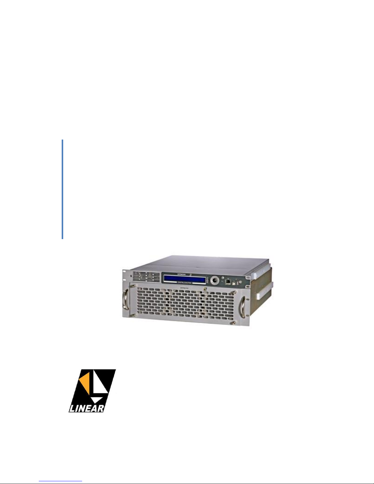
Linear AT71-250 User manual
Other Linear Transmitter manuals

Linear
Linear DXS-31 User manual

Linear
Linear miniTransmitter Delta-3 Series Administrator guide

Linear
Linear 1050 User manual

Linear
Linear DXT-61/EC User manual

Linear
Linear DT-2A Administrator guide

Linear
Linear WT00Z-1 User manual

Linear
Linear MDT User manual

Linear
Linear MULTI-CODE 4140 User manual

Linear
Linear Multi-Code 3089 User manual

Linear
Linear AT7400 User manual

Linear
Linear Mini-Code 3083 User manual

Linear
Linear GT-31 User manual

Linear
Linear LINEARCOM3000 User manual

Linear
Linear Supervised Emergency Alarm Transmitter... User manual

Linear
Linear ADVANCED AT7200 User manual

Linear
Linear XT-1H User manual

Linear
Linear LMT-1 User manual

Linear
Linear DIGITAL TRANSMITTER GT-30 User manual

Linear
Linear MegaCode ACT-21 User manual

Linear
Linear MULTI-CODE 1051 User manual


Popular Transmitter manuals by other brands


Inovonics
Inovonics EchoStream EN1210W installation instructions

IKONNIK
IKONNIK KA-6 quick start guide

Rohde & Schwarz
Rohde & Schwarz SR8000 Series System manual

Audio Technica
Audio Technica UniPak ATW-T93 Installation and operation

NIVELCO
NIVELCO EasyTREK SCA-300 Series Programming manual

Honeywell
Honeywell 5816WMBR installation instructions