Link-Belt PULSE Use and care manual

Link‐Belt Pulse
Calibration Manual
(Level 2)
Access on Cranes with Outrigger Sensors
®
Link‐Belt is a registered trademark.


Link‐Belt Pulse Calibration Manual

Table Of Contents
General Information . . . .. . . .. . . . . .. . . . .. .. . . .. .. . . . .. .. .. . . .. .. . . . . . .. . . .. .. . . .. . .. . . .. .. .. . 1
Display ButtonIdentification . . .. . . .. . . . . . .. . . .. .. . . . .. .. . . .. .. .. . . . .. .. . . . . .. . . . .. .. . . .. .. . . 1
Calibration And Programming Procedures . . . .. .. . . .. .. .. . . .. .. . . . . . .. . . .. .. . . .. . .. . . .. .. .. . . 2
Boom Length Calibration . . . . . . . . . . . . . . . . . . . . . . . . . . . . . . . . . . . . . . . . . . . . . . . . . . . . . . . . . . . . . . . . . . . 3
Zero Telescope Cylinder Calibration . . . . . . . . . . . . . . . . . . . . . . . . . . . . . . . . . . . . . . . . . . . . . . . . . . . . . . . . 3
Calibrate Boom Length –PAT Reel Initial Setup . . . . . . . . . . . . . . . . . . . . . . . . . . . . . . . . . . . . . . . . . . . . . . 6
Calibrate Boom Length
-
Pin And Latching Booms . . . . . . . . . . . . . . . . . . . . . . . . . . . . . . . . . . . . . . . . . . . 7
Calibrate Boom Length –Full Power Booms . . . . . . . . . . . . . . . . . . . . . . . . . . . . . . . . . . . . . . . . . . . . . . . . . 8
Boom Angle Calibration . . . . . . . . . . . . . . . . . . . . . . . . . . . . . . . . . . . . . . . . . . . . . . . . . . . . . . . . . . . . . . . . . . . . 9
Swing Angle Calibration . . . . . . . . . . . . . . . . . . . . . . . . . . . . . . . . . . . . . . . . . . . . . . . . . . . . . . . . . . . . . . . . . . . . 11
Pressure Programming . . . . . . . . . . . . . . . . . . . . . . . . . . . . . . . . . . . . . . . . . . . . . . . . . . . . . . . . . . . . . . . . . . . . . 12
Program Pressure Transducers . . . . . . . . . . . . . . . . . . . . . . . . . . . . . . . . . . . . . . . . . . . . . . . . . . . . . . . . . . . . 12
Reset Pressure Transducers . . . . . . . . . . . . . . . . . . . . . . . . . . . . . . . . . . . . . . . . . . . . . . . . . . . . . . . . . . . . . . . 13
Outrigger Programming And Calibration . . . . . . . . . . . . . . . . . . . . . . . . . . . . . . . . . . . . . . . . . . . . . . . . . . . . . . 14
Hydraulic Fly Angle Sensor Calibration . . . . . . . . . . . . . . . . . . . . . . . . . . . . . . . . . . . . . . . . . . . . . . . . . . . . . . . 16
Main Winch Friction Calibration . . . . . . . . . . . . . . . . . . . . . . . . . . . . . . . . . . . . . . . . . . . . . . . . . . . . . . . . . . . . . . 18
Auxiliary Winch Friction Calibration . . . . . . . . . . . . . . . . . . . . . . . . . . . . . . . . . . . . . . . . . . . . . . . . . . . . . . . . . . . 22
Bias And Slope Sliders Explanation . . . . . . . . . . . . . . . . . . . . . . . . . . . . . . . . . . . . . . . . . . . . . . . . . . . . . . . . . . 24
Fly Weight Calibration (Fly Erected) . . . . . . . . . . . . . . . . . . . . . . . . . . . . . . . . . . . . . . . . . . . . . . . . . . . . . . . . . . 25
Fly Weight Calibration (Fly Stowed) . . . . . . . . . . . . . . . . . . . . . . . . . . . . . . . . . . . . . . . . . . . . . . . . . . . . . . . . . . 27
Diagnostics . .. .. .. . . .. .. .. . . . .. .. . . .. .. .. . . . .. .. . . . . .. . . .. .. . . .. . .. . . .. .. .. . . .. . .. . . . . .. . . . 29
CAN Viewer . . . . . . . . . . . . . . . . . . . . . . . . . . . . . . . . . . . . . . . . . . . . . . . . . . . . . . . . . . . . . . . . . . . . . . . . . . . . . . . 29
Active System Faults . . . . . . . . . . . . . . . . . . . . . . . . . . . . . . . . . . . . . . . . . . . . . . . . . . . . . . . . . . . . . . . . . . . . . . . 30
System Fault Log . . . . . . . . . . . . . . . . . . . . . . . . . . . . . . . . . . . . . . . . . . . . . . . . . . . . . . . . . . . . . . . . . . . . . . . . . . 30
Boom Telescope Diagnostics . . . . . . . . . . . . . . . . . . . . . . . . . . . . . . . . . . . . . . . . . . . . . . . . . . . . . . . . . . . . . . . . 31
Outrigger Position Diagnostics . . . . . . . . . . . . . . . . . . . . . . . . . . . . . . . . . . . . . . . . . . . . . . . . . . . . . . . . . . . . . . 32
Sensor Data . . . . . . . . . . . . . . . . . . . . . . . . . . . . . . . . . . . . . . . . . . . . . . . . . . . . . . . . . . . . . . . . . . . . . . . . . . . . . . 33
Setup . . .. . . . .. . . . . .. . . .. . .. . . .. .. . . .. .. .. . . . .. .. . . . . . .. . . .. .. . . . .. .. . . .. .. .. . . . .. .. . . . . .. . 34
Enable Options . . . . . . . . . . . . . . . . . . . . . . . . . . . . . . . . . . . . . . . . . . . . . . . . . . . . . . . . . . . . . . . . . . . . . . . . . . . . 34
Counterweight . . . . . . . . . . . . . . . . . . . . . . . . . . . . . . . . . . . . . . . . . . . . . . . . . . . . . . . . . . . . . . . . . . . . . . . . . . . 34

Auxiliary Lifting Devices . . . . . . . . . . . . . . . . . . . . . . . . . . . . . . . . . . . . . . . . . . . . . . . . . . . . . . . . . . . . . . . . . . . 35
Winch . . . . . . . . . . . . . . . . . . . . . . . . . . . . . . . . . . . . . . . . . . . . . . . . . . . . . . . . . . . . . . . . . . . . . . . . . . . . . . . . . . . 36
Misc . . . . . . . . . . . . . . . . . . . . . . . . . . . . . . . . . . . . . . . . . . . . . . . . . . . . . . . . . . . . . . . . . . . . . . . . . . . . . . . . . . . . 37
Front Winch Rope Capacity . . . . . . . . . . . . . . . . . . . . . . . . . . . . . . . . . . . . . . . . . . . . . . . . . . . . . . . . . . . . . . . . . 38
Rear Winch Rope Capacity . . . . . . . . . . . . . . . . . . . . . . . . . . . . . . . . . . . . . . . . . . . . . . . . . . . . . . . . . . . . . . . . . 38
About . . . .. . . .. . . . . . .. . . .. .. . . . .. .. . . .. .. .. . . .. .. . . . . . .. . . .. .. . . . .. .. . . .. .. .. . . . .. .. . . . . .. . 39
Appendix A ................................................................................ 40
Friction And Dynamic Calibration . . . . . . . . . . . . . . . . . . . . . . . . . . . . . . . . . . . . . . . . . . . . . . . . . . . . . . . . . . . . 40
Appendix B ................................................................................ 45
HED Programming Instructions . . . . . . . . . . . . . . . . . . . . . . . . . . . . . . . . . . . . . . . . . . . . . . . . . . . . . . . . . . . . . . 45
Appendix C .. . . .. . .. . . .. .. .. . . .. .. . . . .. .. .. . . .. .. . .. . . .. .. . . .. .. . .. . . .. .. . . . . .. . . . .. .. . . .. . 54
ECM Programming Instructions . . . . . . . . . . . . . . . . . . . . . . . . . . . . . . . . . . . . . . . . . . . . . . . . . . . . . . . . . . . . . 54
General Information
1.
Required Tools
a.
Testweights
-
[1approximately2,000lb
(907kg)
and 1 approximately 10,000 lb
(4 536kg)
]
b.
Measuring Tape
-
200 –300 ft graduated in
tenth’s of a foot
c.
Digital level
2.
For calibration purposes, boom mode must be se-
lected to allow full extension of all boom sections.
REFERTOTHECRANERATINGMANUALFOR
SAFE OPERATION.
3.
If software is to be updated, record
ALL
Friction
Slider Bar Values
BEFORE
programming any of
the Electronic Control Modules (ECM's).
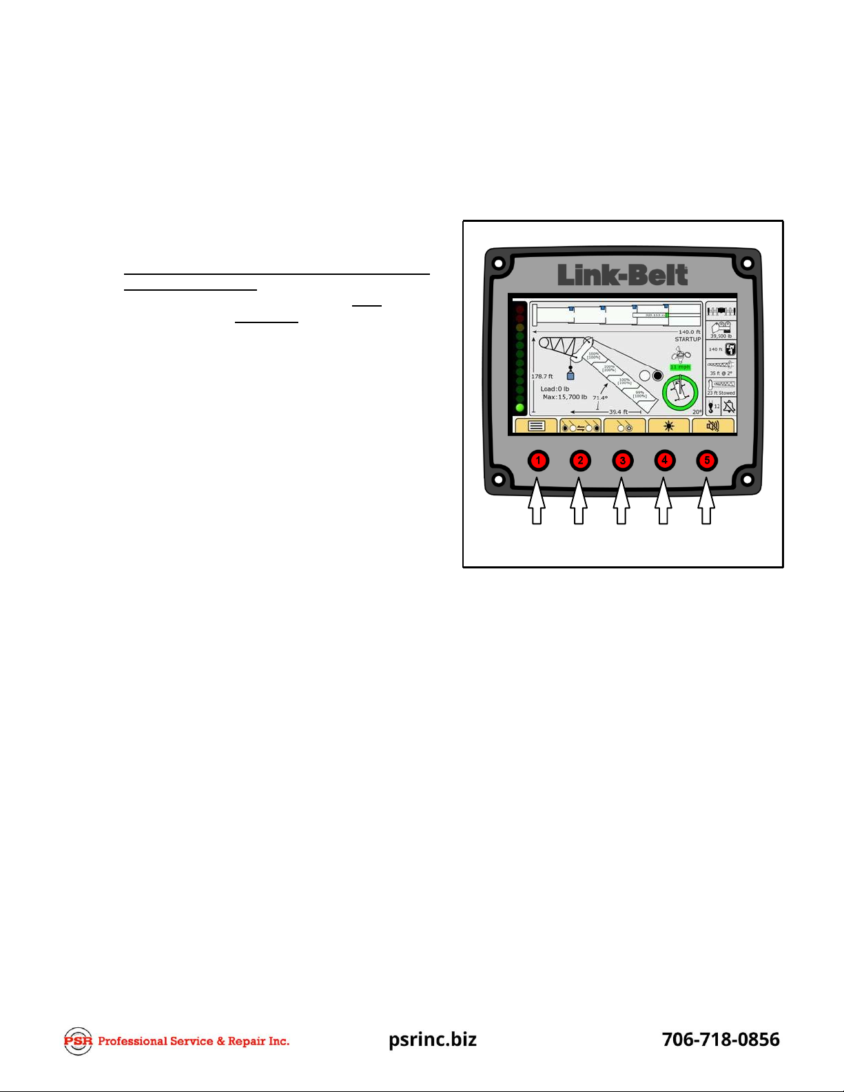
Display Button Identification
1. The Buttons on the actual Pulse Display are not
numbered, but for the purpose of this document,
Buttons 1 through 5,starting on the left,will beref-
erenced as Button numbers as shown below.
1
2
3
4
5

Calibration And Programming
Procedures
1.
Calibration Mode Entry
a.
Press Button 1 to enter the Main Menu.
c.
Use Buttons 2 and/or 4 to navigate to the first
number of the Password and press Button 3 to
enter the number. Follow this procedure for
each number of the Password. Press Button 3
one more time when checkmark is highlighted.
1.
Level 2 Password is 22222.
2.
When Password is entered correctly,Main
Menu, Access Level 2 screen should ap-
pear.
b.
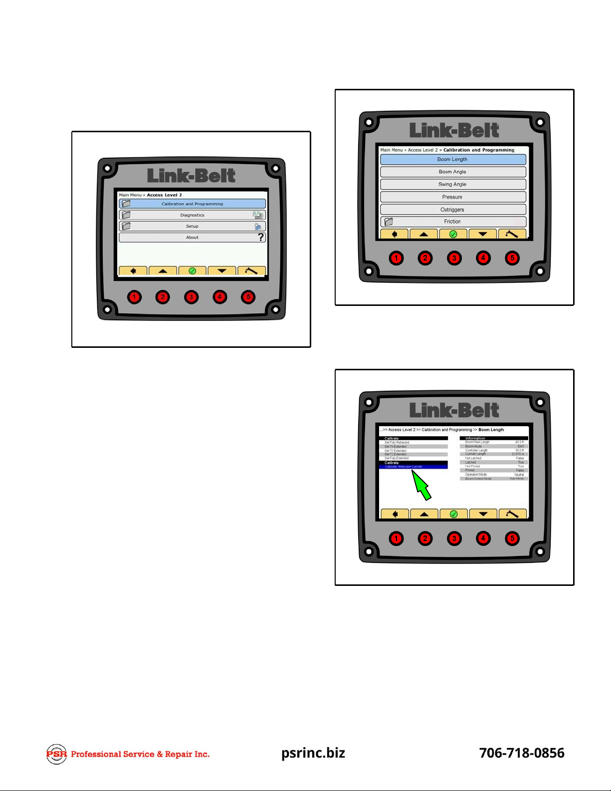
Press Buttons 1, 3, and 5 simultaneously, then
release, to enter Access Level 2.
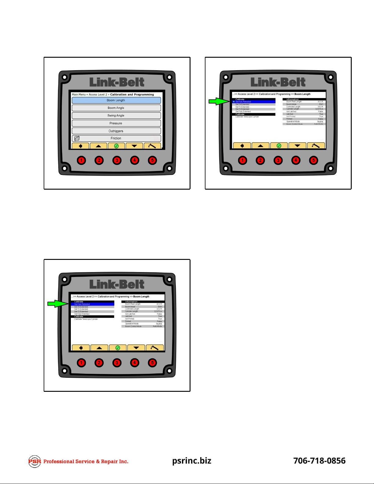
Boom Length Calibration
Zero Telescope Cylinder Calibration
1.
Fully retract the boom.
2.
In Access Level 2, use Buttons 2 and/or 4 tonavig-
ate to Calibration and Programming.
3.
Press Button 3 to enter Calibration and Program-
ming.
4.
Use Buttons 2 and/or 4 to navigate to Boom
Length.
5.
Press Button 3 to enter Boom Length.
6.
Use Buttons 2 and/or 4 to navigate to Calibrate
Telescope Cylinder.
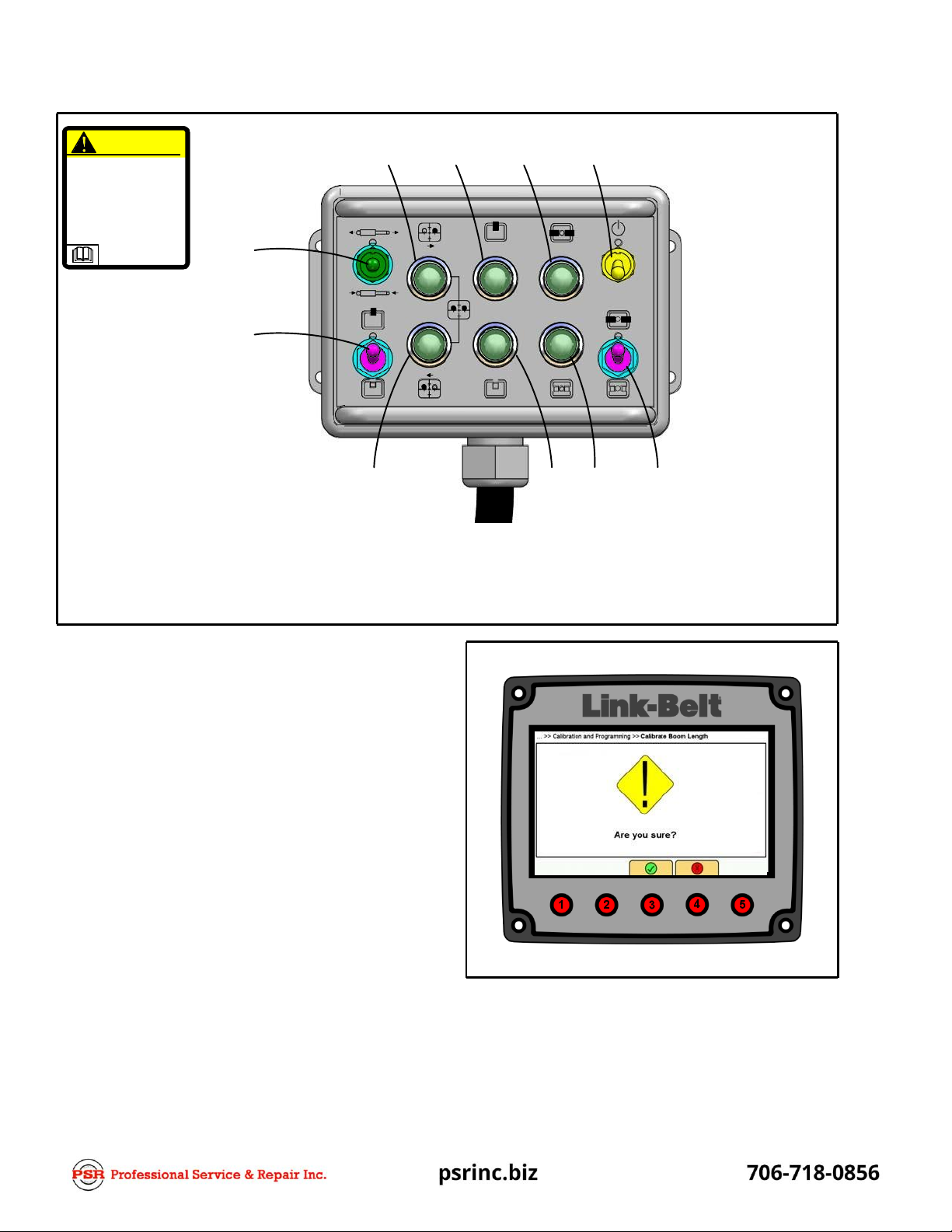
7.
Connect the Manual Control Box to the Manual
Mode Plug on the crane. Refer to the Crane Oper-
ator's Manual for the location of the connection.
8.
Push the Activate Switch up and hold. Push the
Pin/Unpin Switch up to PIN and the Latch/Unlatch
Switch down to UNLATCH.
9.
Confirm that the PINNED and NOT LATCHED lights
are illuminated. The telescope cylinder may have
to be extended or retracted slightly to obtain NOT
LATCHED.
10.
Fully retract the telescope cylinder until it bottoms
out.
11.
Press Button 3 to set the telescope cylinder zero
point.
12.
The Display should show question, “Are you sure?”
13.
Press Button 3 to confirm “Yes” or press Button 4 to
confirm “No”.
CAUTION
Manual mode is intended
only for emergency
operation.
Improper operation of the
boomin manual mode can
cause major damage tothe
boom.
7
8
9
10
1
2
6
5
4
3
1.
2.
3.
4.
Extend/Retract Switch
Pin/Unpin Switch
Latch/Unlatch Switch
Not Latched IndicatorLight
5.
6.
7.
Not Pinned Indicator Light
Latch Forward Indicator Light
Latch Rearward IndicatorLight
8.
Pinned IndicatorLight
9.
Latched Indicator Light
10. Activate Switch
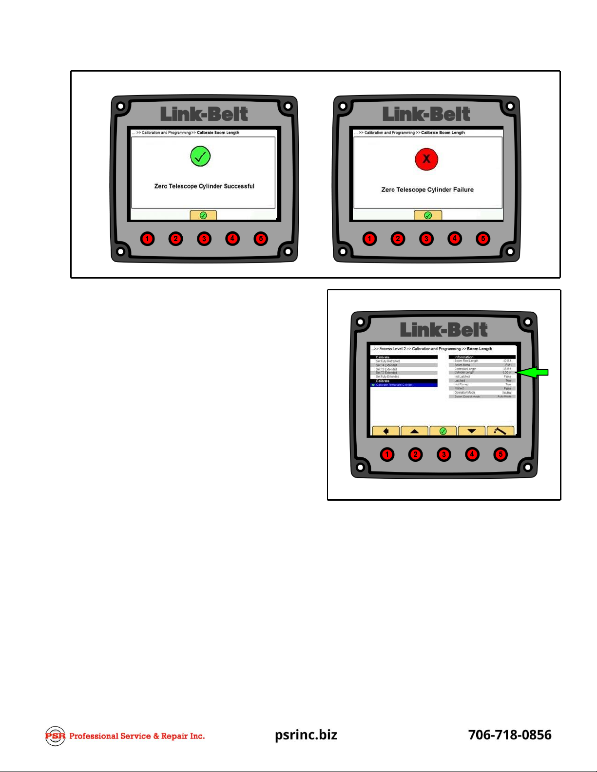
14.
Depending on the previous inputs, “Zero Tele-
scope Cylinder Successful” or “Zero Telescope
Cylinder Failure” should be shown.
Note: If a “Zero Telescope Cylinder Failure” is
shown when trying to zero the telescope cylin-
der, confirm that the Manual Control Box is
plugged in and the “PINNED and NOT
LATCHED” sensors are active.
15.
Extend the telescope cylinder slightly and retract it
again to verify the telescope cylinder returns to
0.00” ±.009”
(0.00cm
±
.023cm)
.
16.
With “Zero Telescope Cylinder Successful” discon‐
nect and properly store the Manual Control Box.
17.
Press and hold the telescope pedal to return the
telescope cylinder to its starting point and let the
system Latch and Unpin the section.
18.
Zero Telescope Cylinder is complete.
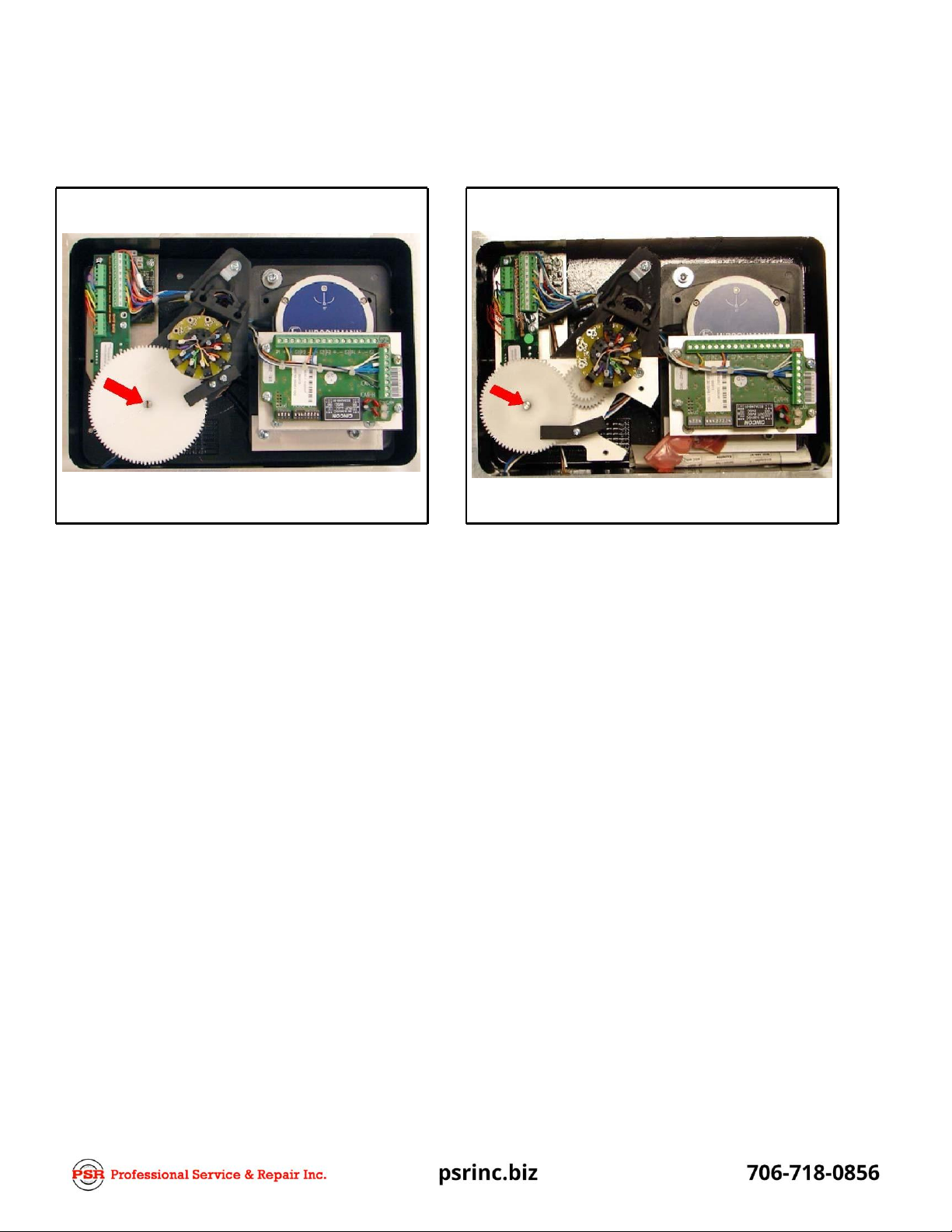
2-Gear Reeling Drum
3-Gear Reeling Drum
Calibrate Boom Length –PAT Reel Initial Setup
1.
Remove cover from PAT reel.
2.
Adjust soft stop on length potentiometer.
a.
Soft stop adjustment for 2-gear reel, use small
screwdriver and rotate potentiometer counter-
clockwise until potentiometer stops.
b.
Soft stop adjustment for 3-gear reel, use small
screwdriver and rotate potentiometer clock-
wise until potentiometer stops.
3.
Replace cover on PAT reel.
4.
Setup complete.
Calibrate Boom Length
-
Pin And Latching Booms
Note: Adjustsoft stop on PATreel first. Refer to
“
Ca
li
bra
t
e
Boom
Length
-
P
A
T
Ree
l
Ini
ti
a
l
Se
tu
p
”
.
1.
In Access Level 2, Calibration and Programming,
use Buttons 2 and/or 4 to navigate to Boom
Length.
2.
Press Button 3 to enter Boom Length.
4.
Fully retract the boom for the first calibration point.
With the boom fully retracted and in the “PINNED
and LATCHED” condition, press Button 3 which
will place a green checkmark by the
Set Fully Re-
tracted
position as in the example above.
Note: Pressing Button 2 and/or 4 will navigate
through the extended sections to be calibrated
highlighting them in BOLD type.
5.
Extend the boom until the next section is extended
and is PINNED and NOT LATCHED and the tele-
scope cylinder is returning to the home position.
Note: Section must be PINNED and NOT
LATCHED before calibration will be accepted.
6.
Press Button 3 to set the next extended section
boom length and a green checkmark will appear
indicating the calibration point. Repeat this pro-
cedure until all sections have been extended.
Note: The last section will not PIN and UNLATCH.
7.
When completed all sections will have green
checkmarks indicating all sections have been cal-
ibrated.
8.
Boom Length Calibration is now complete.
3. Use Buttons 2 and/or 4 to navigate to Set Fully Re-
tracted.

Calibrate Boom Length –Full Power Booms
Note: Adjustsoft stop on PATreel first. Refer to
“
Ca
li
bra
t
e
Boom
Length
-
P
A
T
Ree
l
Ini
ti
a
l
Se
tu
p
”
.
1.
In Access Level 2, Calibration and Programming,
Use Buttons 2 and/or 4 to highlight BoomLength.
2.
Press Button 3 to enter Boom Length.
4.
Fully retract the boom for the first calibration point -
with the boom fully retracted, press Button 3 which
will place a green checkmark at the
Set Fully Re-
tracted
position as in the example above.
Note: Pressing Button 2 and/or 4 will scroll
through the extended sections to be calibrated
highlighting them in BOLD type.
5.
Using the Boom Telescope Override Switches ex-
tend the Tip and Outer boom sections.
6.
Press Button 3 to set the extended section boom
length and a green checkmark will appear indicat-
ing the calibration point. Do not retract Tip and
Outer boom sections, proceed to Step 7.
7.
Using the Boom Telescope Override Switches ex-
tend the Center boom section (if equipped, if not
equipped proceed to Step 9).
8.
Press Button 3 to set the extended section boom
length and a green checkmark will appear indicat-
ing the calibration point.
9.
Fully extend the boom.
10.
When completed all sections will have green
checkmarks indicating all sections have been cal-
ibrated.
11.
Boom Length Calibration is now complete.
3.
Use Buttons 2 and/or 4 to highlight Set Fully Re-
tracted.
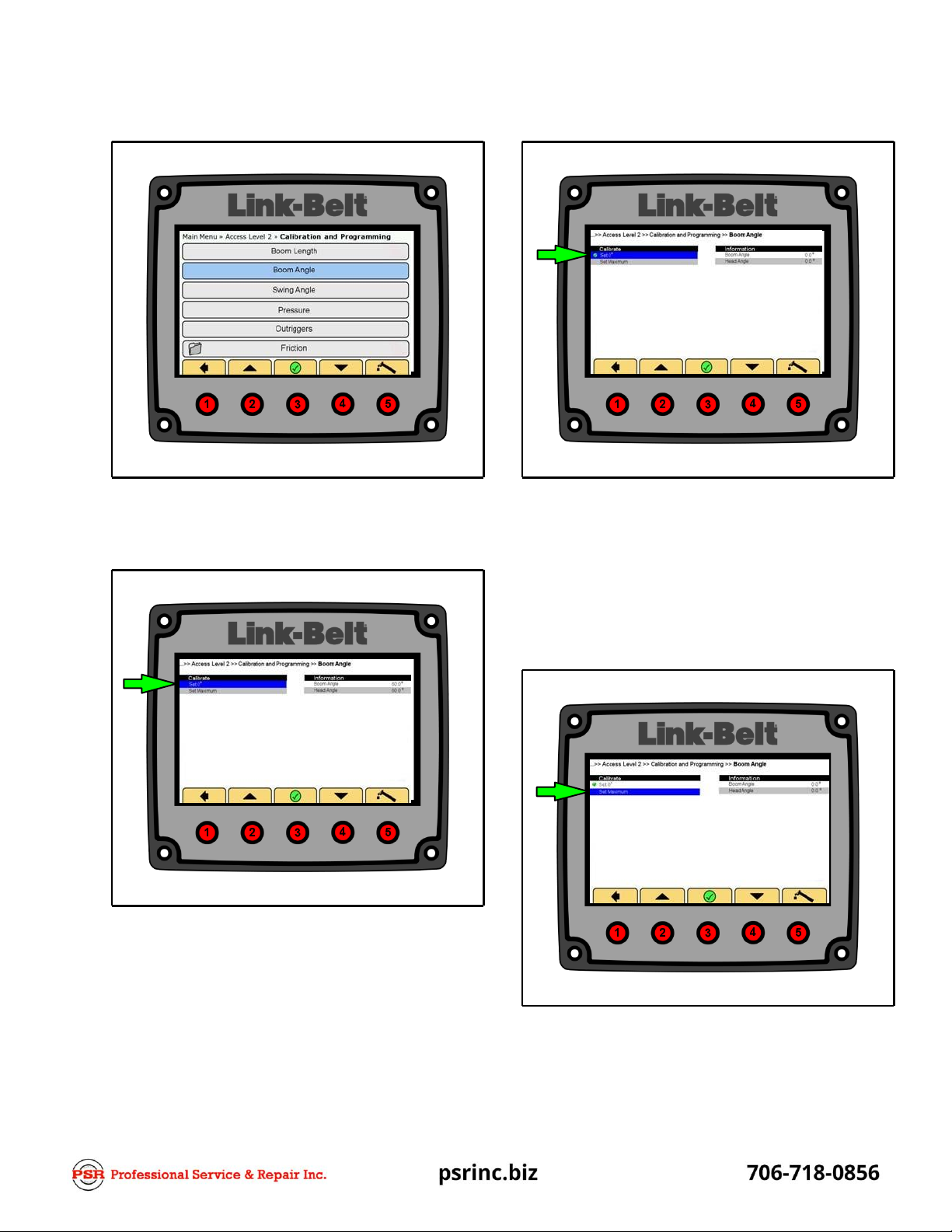
Boom Angle Calibration
1.
In Access Level 2, Calibration and Programming,
use Buttons 2 and/or 4 to navigate to Boom Angle.
2.
Press Button 3 to enter Boom Angle.
6.
A green checkmark will appear indicating position
has been calibrated.
7.
Raise the boom to 80 degrees, verifying with a di-
gital level. (If 80 degrees cannot be obtained use
the next lower whole reading. I.E.
=
79 degrees.)
Note: The Software does not contain a decimal
point so a whole number must be used.
3.
Use Buttons 2 and/or 4 to navigate to Set 0°.
4.
Ensure the boom is at zero degrees, verifying with
a digital level.
5.
Press Button 3 to enter Set 0°.
8.
Use Buttons 2 and/or 4 to navigate to Set Maxim-
um.
9.
Press Button 3 to enter Set Maximum.

10.
Enter actual angle value. I.E. 80 degrees. Use But-
tons 2 and/or 4 to navigate to the first number and
press Button 3 to enter the number. Repeat for the
second number.
11.
Use Buttons 2 and/or 4 to navigate to the green
checkmark.
12.
Press Button 3 to enter the span value.
13.
A green checkmark will appear indicating the posi-
tion has been calibrated.
14.
Boom Angle Calibration is now complete.

Swing Angle Calibration
1.
In Access Level 2, Calibration and Programming,
use Buttons 2 and/or 4 to navigate to Swing Angle.
2.
Press Button 3 to enter Swing Angle.
6.
A green checkmark will appear indicating the 0°
position has been calibrated.
7.
Release the travel swing lock.
8.
Swing to the right.
9.
Ensure degree reading is increasing.
Note: If swing angle decreases, the signal wires
on the swing potentiometer will need to be re-
versed.
10.
Swing the upper directly over the rear of the carrier
and set the travel swing lock.
11.
Use Buttons 2 and/or 4 to navigate to Set 180°.
12.
Press Button 3 to set the 180° position.
13.
A green checkmark will appear indicating the 180°
position has been calibrated.
14.
Swing Angle Calibration is now complete.
3.
Swing the upper directly over the front of the carrier
and set the travel swing lock.
4.
Use Buttons 2 and/or 4 to navigate to Set 0°.
5.
Press Button 3 to set the 0° position.
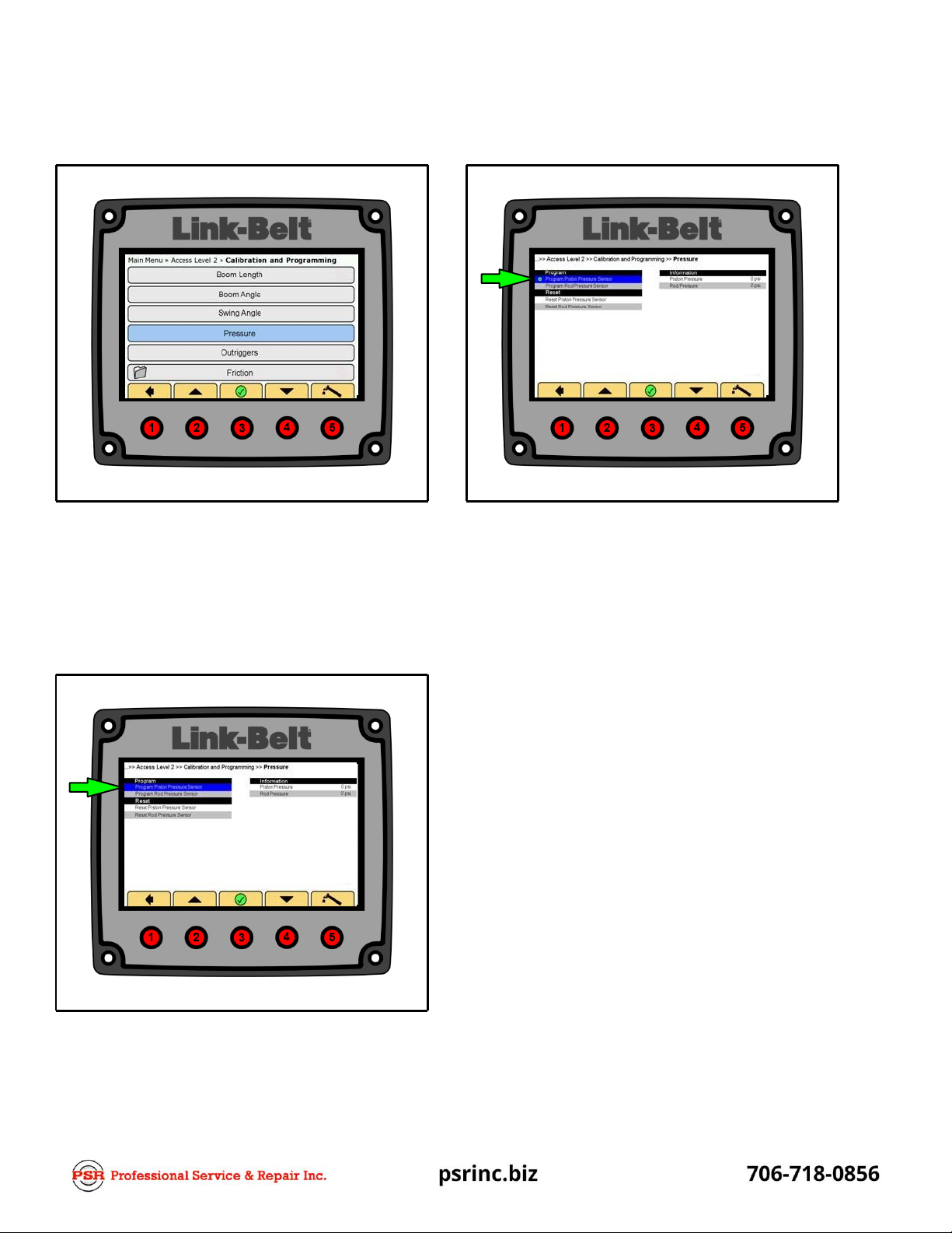
Pressure Programming
Program Pressure Transducers
1.
In Access Level 2, Calibration and Programming,
use Buttons 2 and/or 4 to navigate to Pressure.
2.
Electrically disconnect both pressure transducers
from the system.
3.
Press Button 3 to enter Pressure.
4.
Electrically connect the Piston pressure trans-
ducer.
7.
A green checkmark will appear indicating piston
pressure transducer has been programmed. The
piston pressure transducer readout should now re-
flect hydraulic pressure.
Note: The piston pressure transducer can re-
main connected after it has been programmed.
8.
Electrically connect the Rod pressure transducer.
9.
Use Buttons 2 and/or 4 to navigate to ProgramRod
Pressure Sensor.
10.
Press Button 3 to program the rod pressure trans-
ducer.
11.
A green checkmark will appear indicating the rod
pressure transducer has been programmed. The
rod pressure transducer readout should now re-
flect hydraulic pressure.
12.
Pressure Transducers Programming is now com-
plete.
5.
Use Buttons 2 and/or 4 to navigate to ProgramPis-
ton Pressure Sensor.
6.
Press Button 3 to program the piston pressure
transducer.
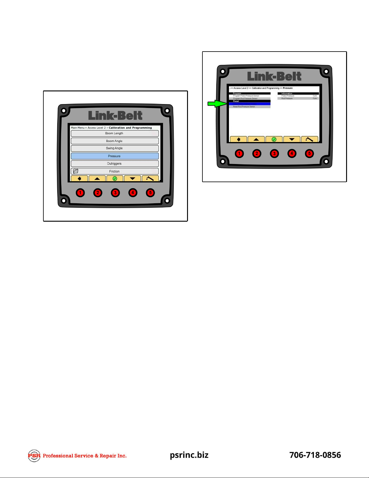
Reset Pressure Transducers
This is used to reset the CAN ID to factory default. If
this procedure is used, the CAN ID’s must be repro‐
grammed by repeating the previous procedures,
“Program Pressure Transducers”.
1.
In Access Level 2, Calibration and Programming,
use Buttons 2 and/or 4 to navigate to Pressure.
2.
Press Button 3 to enter Pressure.
3.
Use Buttons 2 and/or 4 to navigate to Reset Piston
Pressure Sensor.
4.
Press Button 3 to reset the piston pressure trans-
ducer to factory default.
5.
A green checkmark will appear indicating the pis-
ton pressure transducer has been reset.
6.
Use Buttons 2 and/or 4 to navigate to Reset Rod
Pressure Sensor.
7.
Press Button 3 to reset the rod pressure transducer
to factory default.
8.
A green checkmark will appear indicating the rod
pressure transducer has been reset.
9.
Pressure Transducers are now reset to factory
default.

Outrigger ProgrammingAnd
Calibration
This is used to program and calibrate the outrigger
sensors.
1.
In Access Level 2, Calibration and Programming,
use Buttons 2 and/or 4 to navigate to Outriggers.
2.
Press Button 3 to enter Outriggers.
3.
Use the following procedures to Program the out-
rigger sensors.
a.
Disconnect CAN Bus cables from all four out-
rigger beams.
b.
Connect CAN Bus cable to front left outrigger
beam.
Note: This is the sensor connection on the
outrigger cylinder that functions the left out-
rigger beam on the right side of the crane.
c.
Use Buttons 2 and/or 4 to navigate to “Pro‐
gram Front Left”.
d.
Press Button 3 to enter Program Front Left.
Verify the green checkmark appears.
e.
Disconnect CAN Bus cable from front left out-
rigger beam. Connect CAN Bus cable to front
right outrigger beam.
Note: This is the sensor connection on the
outrigger cylinder that functions the right
outrigger beam on the left side of thecrane.
f.
Use Buttons 2 and/or 4 to navigate to “Pro‐
gram Front Right”.
g.
Press Button 3 to enter Program Front Right.
Verify the green checkmark appears.
h.
Disconnect CAN Bus cable from front right
beam. Connect CAN Bus cable to rear left out-
rigger beam.
Note: This is the sensor connection on the
outrigger cylinder that functions the left out-
rigger beam on the right side of the crane.
i.
Use Buttons 2 and/or 4 to navigate to “Pro‐
gram Rear Left“.
j.
Press Button 3 to enter Program Rear Left.
Verify the green checkmark appears.
k.
Disconnect CAN Bus cable from rear left
beam. Connect CAN Bus cable to rear right
outrigger beam.
Note: This is the sensor connection on the
outrigger cylinder that functions the right
outrigger beam on the left side of thecrane.
l.
Use Buttons 2 and/or 4 to navigate to “Pro‐
gram Rear Right”.
m.
Press Button 3 to enter Program Rear Right.
Verify the green checkmark appears.
n.
Connect CAN Bus cables to all outrigger
Table of contents
Other Link-Belt Construction Equipment manuals


Popular Construction Equipment manuals by other brands

Sealey
Sealey SC10LR Quick start gudie

Fassi
Fassi F 240.24 Use and maintenance

Hercules
Hercules FMR 800 operating instructions

Manitowoc
Manitowoc National Crane 800D Operator's and service manual

MULTIQUIP
MULTIQUIP EM120P series Operation and parts manual

Broderson
Broderson IC-200-2J Operation and maintenance manual


 PARTS & INSTALLATION MANUAL")


