manuals.online logo
Brands
  1. Home
  2. •
  3. Brands
  4. •
  5. LINK-MI
  6. •
  7. Controllers
  8. •
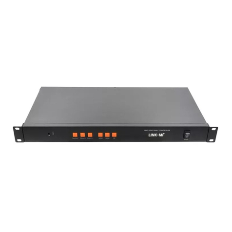
  9. LINK-MI LM-WPS41 User manual

LINK-MI LM-WPS41 User manual

1
LM-WPS41
HD Caption Adder
User
Manual
2
Table of Contents
1. Installation Notes……………………………………3
2.Product Introduction…………………………………5
3. Machine installation…………………………………7
4. Software debugging…………………………………8
5. Remote Control Description………………………12
Chapter One Installation Notes
For your safety and equipment security, please be sure reading the safety instructions
carefully before using the machine.
If you have doubts in the use, please read this manual first. Described in detail in the
body of the device's operation. If you still have questions, please contact us, we will give
you a satisfactory answer as soon as possible.
Specifications subject to release to change without notice, please understand.
When installing, please note the following:
1. power supply:
This device uses 12V / 3A external power supply, power supports 100-240V AC input voltage, in order
to enable the device to work properly, please do not easily replace the brand outside the company and
power specifications.
2. power off:
When you need to move equipment or other work must outage, to shut off all power, including the
power switch, unplug the power plug, so as to ensure the safety of your equipment.
3.Cable:
Items can not put pressure on the power supply lines, signal lines, communication lines, cable should
3
keep from trample or extrusion, to prevent the risk of leakage or short circuit.
4.Signal cable:
Inserting or pulling the signal line to the device, the device needs to be outage, so as not to damage
the device. Hot plug caused damage not covered under warranty.
5.Vents:
The outer surface of the device may have openings for heat dissipation, do not block these openings,
in order to avoid heat build-up, the risk of damage to the equipment or cause fire.
6.Equipment placement:
Should a reasonable settlement for devices such as standard rack mount, chassis, cabinets, or placed
on a stable flat work surface to prevent the unit from dropping.
7.surroundings:
Equipment working environment should pay attention to dust, moisture, in particular, to prevent the
liquid from soaking and splashing into the interior of the device.
8.service:
All repairs should be done by qualified service personnel , untrained Never attempt to repair
equipment. To prevent the risk of electric shock, do not open the cabinet.
9.Safety Precautions:
1). the internal high-voltage equipment, non-professional maintenance personnel shall not open the
case, to avoid danger;
2). non-dripping or splashing, prohibited place any container with liquid items on the device;
3). for the prevention of fire,forbiding a device near the fire;
4). for adequate ventilation, equipment should be maintained at least20CM void of the front and rear
panels;
5).devices should be immediately unplug the power cord and handled by professional maintenance
personnel, such as eerie noise, smell or smoke;
6).In the case of lightning or unused for long periods, unplug the power cord;
7). not stuffed any object to ventilation holes of the device to avoid damage to the equipment or electric
shock;
8). not to place the device near water or other damp places;
9). the device should not be placed near heat sink or other high temperature places;
10). properly organize the power cord to prevent breakage;
11). the following conditions should unplug the device's power cord, handled by qualified service
personnel:
the power cord is damaged or frayed;
When the liquid has been spilled into the device;
The device is dropped or the cabinet damaged;
4
This device malfunction or significant performance changes.
Regularly check the fan is working properly, if the fan does not work you should turn off the device
and disconnect the power supply immediately, handled by the professionals;
This device is not suitable for non-professionals to operate the debugger, users are subject to
professional training and guidance.
Please read carefully before using and this manual should be properly preserved for later use.
Chapter two Product Introduction
LM-WPS41 is a versatile image processor, realizing the caption adder, multi-signal fold line switching ,
signal format conversion, rotate 180 degrees of image, screenshot image , image compression, and
other functions through a single piece of equipment .
Product support one composite video, 1 channel VGA, 1 channel HDMI, 1 USB Signal Input,and 1
HDMI, 1 independent audio signal output. input and output signal can support full HD up to 1920 * 1080
/ 60HZ. All input signals are support the image and audio synchronization switch.
1. hardware Description
5
2. the system topology
3. special splicing
Chapter III Machine Installation
6
1.Unpacking
Check the host and accessories. Including the host, power cable, remote control, RJ-45 to RS-232
adapter, serial cable, warranty card and manual.
2.connecting the cable
Output Connections: The display unit connect with the HDMI interfaces of device's OUTPUT via HDMI
cable; If use an external sound, connect the audio cable to the OUTPUT's A-OUT Interface;
Input connection: input signal that contain USB, HDMI, VGA, AV, USB can access U disk and play the
videos, pictures inside the U disk and so on. Users connect the signal source to be displayed to the
corresponding interfaces inside INPUT box by a cable according to their needs. L, R is the left and right
channel audio with binding Composite video ; A-IN audio bind VGA signal.
RS-232 connection: RJ45 to RS-232 adapter which standard configuration with product access RS232
port of device, then connect with the control computer via RS-232 line.
Power connection: 12V DC power supply which standard configuration with product insert the DC
12V,so the hardware connection is completed, the machine can normal work after setting.
Power on: After connecting the cable above, the configured power adapter of the device insert into an
AC 100-240V power supply, turn on the power switch, power indicator shows green, indicating that the
device is in working condition; red is on standby;on standby state, press the power key of the remote
control to boot and into the normal working condition.
Chapter IV software debugging
After completing the hardware connection, to switch the power on by of remote control, the red
light is on standby, the green light is turned on. Please setting software through the following steps:
1.double-click the icon to run the control software, interface as follows:
7
2.showing the com port number as shown above , you can click directly the of control software
communicate with computer. If the control software does not show the COM port number, Check the
Windows serial port driver is installed . After installation and displays the port number, then restart the
control software to connect.
3.caption adder settings
In input character which will be displayed, click , click at the where
display subtitles,then look at the display unit, you can see the show and the effect of moving of the
enter caption; you can also click to closed captioning display function. And you can set a
variety of display effect of captions:
3.1.text color, the color of display font , font color contain red, green, yellow, blue, black and white .
3.2.Background color - Text background color contain red, green, yellow, blue, black, white, transparent
color .
3.3.show captions - choose to open, the display unit is displayed subtitle; select Off, the display unit
does not display captions.
3.4.text size - that is, the font size, optionally, small, medium and large sizes.
3.5.text position - subtitle show above the display unit; the caption display at the bottom of the display
unit.
3.6.Font's moving speed - still, text display at the center , do not move; medium-speed,font move from
left to right at medium-speed; fast, text fastly moving from left to right.
4.enable the LED function
Click to enable LED function, image can be scaling and screenshots by this feature.
Horizontal and vertical coordinate starting marked as 0, the rightward, the greater the transverse
coordinates; the downward, the greater the longitudinal coordinates, as shown:
8
4.1.LED function:
The main role of LED's function is to make a complete video signal compress to show on a part of the
display unit, this feature is mainly used in LED full color, as shown below:
If the user's terminal display is a full-color LED screen, LED screen's pixels of 1680x960, the Send
card's resolution of 1920 * 1080,setting in this example:
1. click OK after output resolution of the upper right corner of the control software set to 1920 * 1080, as
2.enable the LED function;
3.the input image can be displayed in full-screen on LED full-color screen after changing the width of
the LED functional areas to 1680, the height to 960 and click OK.
4.change the image's display position of the large screen by adjusting the X and Y's starting point of
the region. LED sending card's horizontal and vertical coordinates are generally set to 0, some special
places setting depending on the user's demand.
4.2.LED screenshot function
Any part of a complete signal can be intercepted and Zoom to full screen display by LED screenshot
function, as shown below:
image before intercepting intercepting part of the image and full-screen display
If we want cut out a part of the image, you can estimate the starting point of the X lateral coordinates
and Y longitudinal coordinates of the portion of the image, but also to estimate the width and height of
the part of the image that to be intercepted. Adjusting the X and Y starting point, width, height of partion
of LED screenshot by sliding the mouse to change the value after estimating,and click the "OK" button
to complete. After completion, May not be coincided with you purpose of the part of image you want to
cut out,then debugging the + or - key of X, Y starting point, width, height, until fully consistent .
The horizontal and vertical resolution of screenshot features, the resolutions of computer output to
device shall prevail. Such as,if computer output resolution is 1920 * 1080,so the maximum lateral
resolution of 1920 and vertical resolution of 1080,and according to this pixels and ratio of 1920 * 1080
9
to calculate the part of the screen you wanna intercept when screenshot.
As shown, if the computer input resolution of 1920 * 1080, and you want to cut out the 6th part of the
picture,the methods and steps as follows
1.the starting point of the transverse direction-X for 480 and the longitudinal direction Y as 360 of this
part;
2.estimating the transverse width as 480 and the vertical height as 360 of this section ;
3.by the mouse, pulling to the corresponding value and click OK;
4.After completion, May not be coincided with you purpose of the part of image you want to cut
out,then fine tuning the + or - key of X, Y starting point, width, height, until fully consistent .
Chapter V Remote Control Description
Most functions of LM-WPS41 can be done by remote control,like switching the power and standby
mode of equipment, mute switch, volume control, play on one and the next track of U disc's video , play
/ pause of U disk , subtitles superimposed switch, switching the output resolution, source selection,
switch DVI and HDMI mode, setting LED's feature, LED screenshot settings and others .
1. picture of remote control as well as functions of each key:
10
2.Specially Functional Keys:
Most functions of remote control of the device the same as the functions of the common remote
control of LCD TV,including the U disk playback function, signal source switching. For common
functions not going to describe,only to explain some of the customized features keys of the product:
SWITCH: Click to make subtitles show or closed on the display unit;when display caption, can not
invoke the menu if Press MENU, so you need to turn off the subtitles to call out the menu.
AUTO: VGA input signal may show deflected or colour cast,and can be a key calibration by AUTO;
Numeric key 7: Each time you press the numeric key 7 to switch to a different output resolutions,
respectively, 1024x768,1280x1024,1440x900,1280x720,1920x1080.
Numeric keys 9: Switch DVI or HDMI output mode;
3.key functions of remote control
11
on-off key: power and standby switch of splicer;
Mute switch: U disk playback mute on and off function;
On one, the next song: Play the video of the USB signal path, switching program;
Sound + Sound -: Adjust sound volume;
UA1: signal switch to HDMI by a key;
UA2: signal switch to VGA;
UA3: signal switch to composite video by a key;
UA4: a signal switch to USB by a key;
Menu keys: Menu key, used to parameter settings of splicer, after set up press the Menu to save the
parameter and exit;
SOURCE: Input signal and pull-down to select;
The up, down, left, right navigation key: used to select the each option of menu;
OK key: used to select the content and set the play mode when USB playback;
SWITCH: stitching on and off, for switch the mosaic wall and single-screen full screen display;
Back key: Under USB signal status, is used to return the playback menu;
Play, Pause: for the video or picture playback or pause under USB;
AUTO: for correcting VGA signal;
SHENZHEN LINK-MI TECHNOLOGY CO.,LTD
WWW.LINK-MI.COM E-mail: [email protected]

Other LINK-MI Controllers manuals

LINK-MI LM-TV09S User manual

LINK-MI

LINK-MI LM-TV09S User manual

LINK-MI LM-TV04B User manual

LINK-MI

LINK-MI LM-TV04B User manual

LINK-MI LM-TV08 User manual

LINK-MI

LINK-MI LM-TV08 User manual

LINK-MI LM-TV06-4K2K User manual

LINK-MI

LINK-MI LM-TV06-4K2K User manual
LINK-MI LM-TV04U User manual

LINK-MI

LINK-MI LM-TV04U User manual

LINK-MI LM-MSW1 User manual

LINK-MI

LINK-MI LM-MSW1 User manual

LINK-MI LM-TV16 User manual

LINK-MI

LINK-MI LM-TV16 User manual

LINK-MI LM-TV09-4K2K User manual

LINK-MI

LINK-MI LM-TV09-4K2K User manual

LINK-MI LM-TV08P User manual

LINK-MI

LINK-MI LM-TV08P User manual

LINK-MI LM-TV04H User manual

LINK-MI

LINK-MI LM-TV04H User manual

LINK-MI LM-TV15 User manual

LINK-MI

LINK-MI LM-TV15 User manual

LINK-MI LM-TV09M User manual

LINK-MI

LINK-MI LM-TV09M User manual
LINK-MI LM-TV04M User manual

LINK-MI

LINK-MI LM-TV04M User manual

LINK-MI LM-TV04P User manual

LINK-MI

LINK-MI LM-TV04P User manual

LINK-MI LM-TV04-4K 2K User manual

LINK-MI

LINK-MI LM-TV04-4K 2K User manual

LINK-MI LM-TV12P User manual

LINK-MI

LINK-MI LM-TV12P User manual

LINK-MI LM-TV20 User manual

LINK-MI

LINK-MI LM-TV20 User manual

LINK-MI LM-TV09P User manual

LINK-MI

LINK-MI LM-TV09P User manual

LINK-MI LM-TV21 User manual

LINK-MI

LINK-MI LM-TV21 User manual

LINK-MI LM-TV18 User manual

LINK-MI

LINK-MI LM-TV18 User manual
LINK-MI LM-TV24 User manual

LINK-MI

LINK-MI LM-TV24 User manual

LINK-MI LM-TV06 User manual

LINK-MI

LINK-MI LM-TV06 User manual

LINK-MI LM-TV10 User manual

LINK-MI

LINK-MI LM-TV10 User manual

LINK-MI LM-TV09 User manual

LINK-MI

LINK-MI LM-TV09 User manual

Popular Controllers manuals by other brands

ZIEHL-ABEGG Acontrol PKE-6 operating instructions

ZIEHL-ABEGG

ZIEHL-ABEGG Acontrol PKE-6 operating instructions

Seagull REC2 user manual

Seagull

Seagull REC2 user manual

Sumpo Electric Co., Ltd. P9000 instruction manual

Sumpo Electric Co., Ltd.

Sumpo Electric Co., Ltd. P9000 instruction manual

Tunze Osmolator 3 Instructions for use

Tunze

Tunze Osmolator 3 Instructions for use

Grameyer GRGT-06 Installation and operation manual

Grameyer

Grameyer GRGT-06 Installation and operation manual

RKC INSTRUMENT PF900 Quick operation manual

RKC INSTRUMENT

RKC INSTRUMENT PF900 Quick operation manual

Breezair IWC 10 Installation & operation manual

Breezair

Breezair IWC 10 Installation & operation manual

BENDIX EC-30 ABS-ATC CONTROLLER Troubleshooting

BENDIX

BENDIX EC-30 ABS-ATC CONTROLLER Troubleshooting

Verkada AC41 install guide

Verkada

Verkada AC41 install guide

MOVETEC MCP-TDH6 user guide

MOVETEC

MOVETEC MCP-TDH6 user guide

Pentatech SL 04 instruction manual

Pentatech

Pentatech SL 04 instruction manual

Fisher FIELDVUE DVC6200 instruction manual

Fisher

Fisher FIELDVUE DVC6200 instruction manual

Morningstar TriStar TS-60M Installation, operation and maintenance manual

Morningstar

Morningstar TriStar TS-60M Installation, operation and maintenance manual

thomann the t.racks DSP 4x4 Mini Amp manual

thomann

thomann the t.racks DSP 4x4 Mini Amp manual

Mitsubishi alpha 2 Hardware manual

Mitsubishi

Mitsubishi alpha 2 Hardware manual

Ricoh 700 Series operating instructions

Ricoh

Ricoh 700 Series operating instructions

Siemens IP Control Center N152 Technical product information

Siemens

Siemens IP Control Center N152 Technical product information

Banner Sure Cross DXM1200-Bx instruction manual

Banner

Banner Sure Cross DXM1200-Bx instruction manual

manuals.online logo
manuals.online logoBrands
  • About & Mission
  • Contact us
  • Privacy Policy
  • Terms and Conditions

Copyright 2025 Manuals.Online. All Rights Reserved.