Content
1 General notes ............................................................. 3
1.1 Structure of the operating instructions ...................................... 3
1.2 Targetgroup.......................................................... 3
1.3 E clusion of liability .................................................... 3
1.4 Copyright ............................................................ 3
2 Safety information ......................................................... 3
2.1 Use as intended....................................................... 3
2.2 E planations of symbols ................................................ 4
2.3 Product safety ........................................................ 4
2.4 Requirements placed on the personnel / due diligence ......................... 4
2.5 Start-up and during operation............................................. 4
2.6 Workonthedevice .................................................... 5
2.7 Modications / interventions in the device ................................... 5
2.8 Operator’s obligation of diligence .......................................... 5
2.9 Employmentofe ternalpersonnel......................................... 5
3 Product overview .......................................................... 6
3.1 Operational area ...................................................... 6
3.2 Maintenance.......................................................... 6
3.3 Transport............................................................ 6
3.4 Storage ............................................................. 6
3.5 Waste disposal / recycling ............................................... 6
4 ounting................................................................. 6
4.1 General notes ........................................................ 6
4.2 Minimum space requirement ............................................. 7
4.3 Outdoor installation .................................................... 7
4.4 Installation location for agriculture ......................................... 7
4.5 Temperature inuences during commissioning ................................ 7
5 Electrical installation ....................................................... 8
5.1 Safety precautions ..................................................... 8
5.2 EMC-compatible installation .............................................. 8
5.2.1 Motor feeder cable .............................................. 8
5.2.2 Signal cable ................................................... 8
5.3 Mains connection ...................................................... 8
5.4 Motor connection ...................................................... 9
5.4.1 Running noise ................................................. 9
5.5 Motor protection ....................................................... 9
5.6 Signal or sensor connection (E1 = Analog In 1)............................... 9
5.7 Output voltage 10 - 10 V (A = Analog Out) .................................. 9
5.8 Voltage supply for e ternal devices (+24V, GND) ............................. 10
5.9 Enable, device ON / OFF (Digital In 1 = D1) ................................. 10
5.10 Potential at control voltage connections ..................................... 10
6 Operating and display elements .............................................. 11
7 Base setup ............................................................... 12
7.1 Programming of the desired function (Speed controller / P-Controller).............. 12
7.2 Select operation mode .................................................. 12
7.3 Function of dipswitches for operation as Speed controller 1.01 (DIP
|
1
|
=
|
OFF
|
).... 13
7.4 Function of dipswitches for operation as P-Controller 2.01 ,3.01 ,(DIP
|
1
|
=
|
ON
|
). 13
7.5 MinimumspeedcutoffDIP2............................................. 13
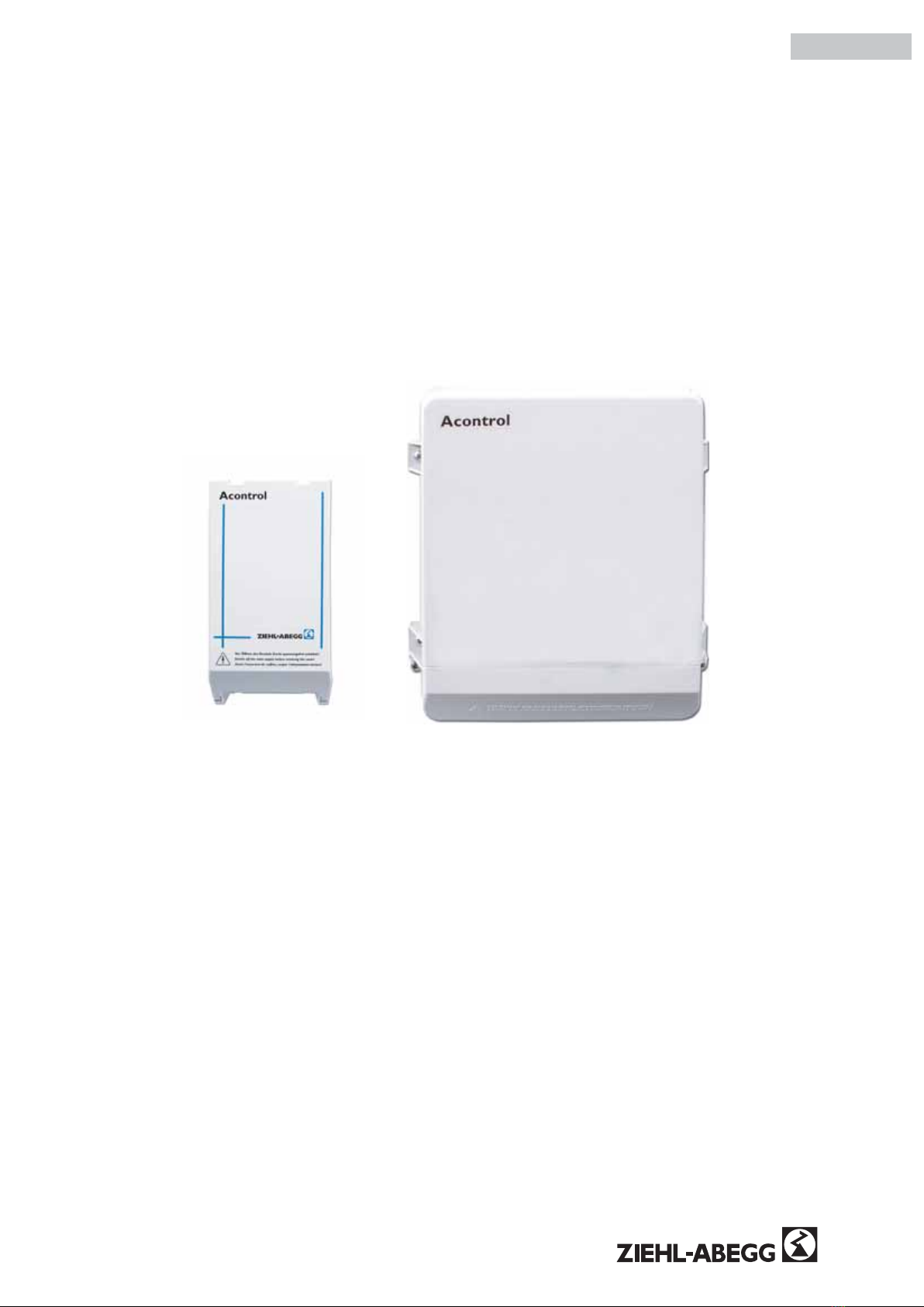
Operating Instructions Acontrol –model series PKE-6 /-10 / PKE-14
L-BAL-E042-GB 1002 Inde 002 Part.-No. 00163314-GB
1/26