GAMMA instabus
Technical Product Information
December 2014
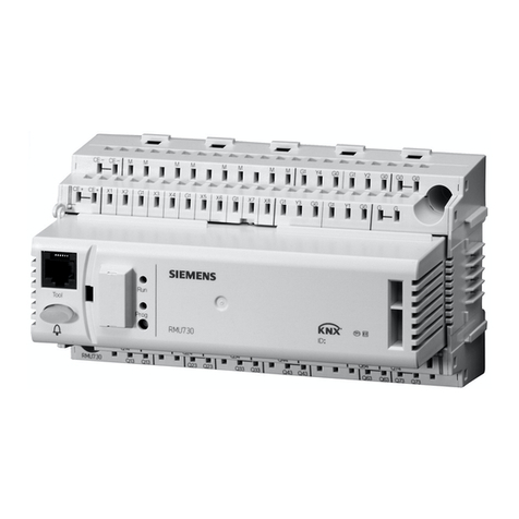
IP Control Center N152 5WG1 152-1AB01
Technical Manual N 152, 4 Pages Siemens AG
Infrastructure & Cities Sector, Building Technologies
Update: http://www.siemens.com/gamma ãSiemens AG 2014 Control Products and Systems
Subject to change without further notice. P. O. Box 10 09 53, D-93009 Regensburg
2.11.1.15/2
Installation Instructions
The device can be used for permanent interior installa-
tions in dry locations within distribution boards or small
casings with DIN rail EN 60715-TH35-7.5.
ΥWARNING
·The device may only be installed and commissioned
by a licensed electrician.
·Exposed sections of rail with integrated data rails are
to be covered with the cover 5WG1 192-8AA01.
·The relevant safety and accident prevention rules are
to be obeyed.
·The device must not be opened.
·When planning and installing electrical systems, the
relevant national directives, rules and regulations of
the country in question are to be obeyed.
Technical Specifications
Power supply
·Bus voltage: supplied via the KNX bus line
·Operating voltage:
from an external SELV power supply DC 24 V
nominal,
permissible input voltage range: DC 12 ... 30 V,
(for class 2 only),
·Power consumption: max. 1,2 W @ 24 V DC
·Recommended power supplies:
–LOGO! Power 24 V / 1,3 A, (class 2),
Rated input voltage AC 100…240 V wide range,
Input voltage range AC 85…264 V,
Constant current supply DC 24 V / 1,3 A,
Rated output voltage: DC 24 V,
Width: 3 SU
–LOGO! Power 24 V / 2,5 A,
Rated input voltage AC 100…240 V wide range,
Input voltage range AC 85…264 V,
Constant current supply DC 24 V / 2,5 A,
Rated output voltage: DC 24 V,
Width: 4 SU
–LOGO! Power 24 V / 4 A,
Rated input voltage AC 100…240 V wide range,
Input voltage range AC 85…264 V,
Constant current supply DC 24 V / 4 A,
Rated output voltage: DC 24 V,
Width: 5 SU
Network communication
·IP-connection via Ethernet, speed 100 Mbit / second
·IP address allocation via DHCP service or fixed IP ad-
dress
Connections
·Bus line: Bus terminal (black-red), without screws
0,6...0,8 mm Ø single core
Insulation strip length 5 mm
·Ethernet 10/100 Mbps, connection: RJ45 socket
·Power supply:
Bus terminal (yellow-white), without screws
0,6...0,8 mm Ø single core
Insulation strip length 5 mm
Control elements
·1 learning button:
to change between normal and addressing modes
Display elements
·1 red LED: ERR-LED signals fault status
·1 yellow LED: LK-LED signals device Ethernet readi-
ness
·1 red LED: to indicate normal mode / addressing mode
Mechanical specifications
·Dimensions: DIN-rail mounted device,
Width 4 SU (1 SU = 18 mm), height 55 mm
·Fire load: approx. 3.300 kJ
·Weight: approx. 150 g
Electrical safety
·Degree of contamination: 2
·Type of protection (to EN 60529): IP 20
·Protection class: (to IEC 1140) III
·Overvoltage category: III
·Bus: Safety Extremely Low Voltage SELV DC 24 V
Reliability
Failure rate: 795 fit according SN29500
EMC criteria
·Meets EN 50428:2005 + A1:2007 + A2:2009 and
EN 61000-6-2:2005, EN 61000-6-3:2007 + A1:2011
