manuals.online logo
Brands
  1. Home
  2. •
  3. Brands
  4. •
  5. RKC INSTRUMENT
  6. •
  7. Controllers
  8. •
  9. RKC INSTRUMENT PF900 User manual

RKC INSTRUMENT PF900 User manual

Ramp/Soak Controller
IMR02L02-E2
This manual describes the basic key operation and mode selection of the PF900/PF901.
For detailed handling procedures and various function settings, please refer to the following
separate manuals:
• PF900/PF901 Instruction Manual (IMR02L03-E)
The above manuals can be download from our website:
URL: http://www.rkcinst.com/english/manual_load.htm
1. PARTS DESCRIPTION
RESET RUN FIX MAN HOLD
STEP R. SET
PTN END
PF900
PV
TM
H:M:S
SV
††††‡
‰
<<<<<<<<<<‡
!
PTN
SEG
OUT1
1
88
88
2 3 4 5 6 7 8 9 10 11 12
A
LM
DO
TS
A
T
MONI
OUT2
OUT3
MODE
SET
(1)
(16)
(17)
(15)
(18)
(19)
(20)
(21)
(14)(13)(12)(11)
(9)
(8)
(7)
(6)
(5)
(4)
(3)
(2)
(10)
(1) Measured value (PV)
display [Green *]
Displays measured value (PV) or various parameter symbols.
(2) TIME display
[Orange *]
Displays selected time unit: Hour and Minute (H: M) or Minute
and Second (M: S).
(3) SV/Timer display
[Orange *]
Displays Set value (SV), Timer setting time or various
characters.
(4) AT/TS lamp [Green *] AT: Flashes when autotuning is activated.
(After autotuning is completed: AT lamp will go out)
TS: Lights when time signal is turned on.
(5) PTN display [Green *] Displays the pattern number in the execution: 1 to 99.
(6) SEG display
[Green *] Displays the segment number in the execution: 1 to 99.
(7) Gradient state lamp
[Green *]
Displays the state of program in process: rise, soak and fall.
The display flashes when the process is in the wait mode.
(8) Output lamp
[Green *]
Lights when the output (OUT1 to OUT3) corresponding to
each lamp is ON.
Lamp indication becomes as follows for current output and
voltage current.
For an output of less than 0 %: Extinguished
For an output of more than 0 %: Lit
(9) Loader
communication
connector
Setting and monitoring on a personal computer (PC) is
possible if the controller is connected with our cable to a PC
via our USB communication converter COM-K-3 (sold
separately) 1.
Our communication software 2 must be installed on the PC.
(10) Monitor key Use to switch the monitor screen. Pressing this key while any
screen other than the SV setting & Monitor mode screen is
being displayed returns to the Measured value (PV)/Set value
(SV) monitor screen.
(11) Set key Used for parameter calling up and set value registration.
(12) Shift key Shift digits when settings are changed. Used to selection
operation between modes.
(13) DOWN key Decrease numerals.
To scroll through numbers faster, press and hold the DOWN
key in the manual mode.
To turn back to the previous time of the program, press and
hold the DOWN key in the operation mode.
(14) UP key Increase numerals.
To scroll through numbers faster, press and hold the UP key
in the manual mode.
To forward the time of the program, press and hold the UP
key in the operation mode.
(15) Unit display [Green*] Displays unit: °C (°F) or %
Lights % for parameters in unit of %.
(16) Set lock display
[Orange*]
Lights when the settings are locked.
(17) ALM lamp [Red] Lights when alarm (Event or heater break alarm [HBA]) is
turned ON.
Confirm the alarm type at the Event monitor display.
(18) Digital output lamp
[Green*]
Lights when the digital output (DO1 to DO12) corresponding
to each lamp is ON.
(19) Program pattern/
Bar graph display
[White]
Displays program patterns or bar graph for manipulated value
(MV). Red display is selectable at event or self-diagnostic
error.
* PF901: White
1For the COM-K, refer to COM-K Instruction Manual (IMR01Z01-E□).
2Software name: WinUCI-PF900 (Only available as a download from our website.)
(20) State display lamp
[Green or Orange]
RESET: Lights in RESET mode [Orange] **
RUN: Lights in RUN mode [Orange] **
FIX: Lights in FIX mode [Orange] **
MAN: Lights in MAN mode [Orange] **
** Other lamps light in green.
HOLD: Lights when the HOLD key is valid. [Green]
STEP: Lights when the STEP/R.SET key is set to STEP
[Green]
R.SET: Lights when the STEP/R.SET key is set to R.SET
[Green]
PTN: Lights when the PTN/END key is set to PTN [Green]
END: Lights when the PTN/END key is set to END [Green]
(21) RESET: Use to switch to RESET (Control stop) mode.
RUN: Use to switch to RUN (Program control start) mode.
Direct key
FIX: Use to switch to FIX (Fixed set point control) mode.
MAN: Use to switch to MAN (Manual control) mode.
HOLD: Use to stop the process of the program or release the
hold function.
STEP/R.SET
STEP: Use to forward a segment of the program.
R.SET: Use to turn back to the previous parameter setting.
PTN/END
PTN: Use to display the execution pattern setting display.
END: Use to set or release the Program end when setting
program.
2. PARAMETER SETTING MODE
2.1 Transfer to Each Mode
The controller has five different setting modes, and all settable parameters belongs to one of
them. The following chart show how to access different setting mode.
 Input type and range display
This instrument immediately displays input type symbol and input range following power ON.
Example: When sensor type is K thermocouple (−200 to +1372 °C)
2.2 Parameter Selection within Mode
 SV setting & Monitor mode
It is possible to set SV which is a control target and also to monitor PV, SV, MV, etc.
* Fix mode: Fixed set point control mode
 Parameter setting mode
It is possible to set any parameter relating to control.
* Fix mode: Fixed set point control mode
PF900/PF901 Quick Operation
Manual
A
ll Rights Reserved, Copyright 2009, RKC INSTRUMENT INC.
InP
@$
K
RANGE
-200 1372
Symbol
Unit for input display
TC/RTD input:
°C or °F
Voltage/Current input:
No display
Automatically
(in 2 seconds)
Input range high
Input range low
Input type symbol:
Symbol KJTSREbn P W
TC
Input type KJTSREBNPLⅡW5ReW26Re
Symbol U L PR PT JP V I
TC RTD Voltage Current
Input type U L PR40-20 Pt100 JPt100 V mA
Power ON
LEVEL
000:00 000000
TIME
000:00 00000
Segment level
[Factory set value: 0]
Segment time
[Factory set value: 0:00]



28
000:00 00000
28
PTN.TM 0:00
28
RPT.SG 0
28
RPT.PN 0
28
RPT.PR 0
28
CT1 0
28
CT2 0
28
EV ooooooo
28
TS oooooooo
28
MV1 0.0
28
MV2 0.0
28
WAIT OOO
PV/SV monitor
Pattern remaining time
monitor
Segment repeat
remaining time/
execution time monitor
Pattern repeat time/
execution time monitor
Total pattern repeat
remaining time/
execution time monitor
Current transformer 1
(CT1) input value
monitor
Current transformer 2
(CT2) input value
monitor
Event state monitor
Time signal state
monitor
Manipulated output
value 1 (MV1) monitor
Manipulated output
value 2 (MV2) monitor
Wait condition monitor












For details of the SV setting & Monitor mode, refer to the
PF900/PF901 Instruction Manual (IMR02L03E-).
Automatically
(in 2 seconds)
28
0:00 0
PV/SV monitor
Monitor mode
Press the key can be change the
monitor displays.
Program mode
In PV/SV monitor, press the key. Th
e
display goes to the segment level/time setting.
28
000:00 00000
PV/SV monitor
SV
00000
Set value
[Factory set value: 0]


28
0
PV/SV monitor
28
MV 0.0
PV/SV monitor
Fix mode *
In PV/SV monitor, press the key. The
display goes to the set value setting.
Manual mode
The key and key is used t
o
manipulate output setting in Manual mode.
Executing pattern setting
In PV/SV monitor, press the PTN/END key.
The display goes to the executing pattern
setting.
PV/SV monitor
28
000:00 00000
PTN
00001

Press the PTN/END key
Input type/Input range display
Operation mode
Change operation status/
mode such as Program/
FIX/Manual/RESET and
PID/AT, etc.
SV
setting & Monitor mod
e
•Mode to be selected during
normal operation
•Changes SV, TIME, etc
•Monitor PV, SV, MV, etc
Parameter setting mode
Create program pattern, set the
parameters such as PID and
Event, or set the parameters fo
r
program setting such as the
time signal.
A
utomatically (in 4 seconds)
Power ON
Press and hold the

key
for 2 seconds or more
Press and hold the
key for 2 seconds
or more
Press and hold the

key for 2 seconds or more
Press the

key
while pressing
the key
Press the

key while
pressing the key for
2 seconds or more
Press the

key while
pressing the key for
2 seconds or more
Press the

key while
pressing the key for
2 seconds or more
Setup setting mode
In this mode, it is possible to
set setting items not stored in
the Parameter setting mode.
Some parameters are also
settable in the Engineering
mode.
Press the

key or
Press the key while pressing the key
Parameters in Engineering
mode are settable only when
the controller is in RESET
mode. However, it is possible
to check only the data even
in RUN mode.
Initial level engineering
mode
For details, refer to
PF900/PF901 Instruction
Manual (IMR02L03-E).
Engineering mode
The content relating to the
specification of this product is
set. Set meet application
requirements. For details, refer
to PF900/PF901 Instruction
Manual
(
IMR02L03-E
)
.
PID
PID memory
group setting
block
PID.GR
00001
PID memory group
number
LBD
GR.1 00000
LBD deadband


EVENT
Event memory
group setting
block
EV.GR
00001
Event memory group
number
EV4`
GR.1 -0050
Event 4 set value
(EV4) [low]
 

WAIT
Wait memory
group setting
bloc
k
WT.GR
00001
Wait memory group
number
TM.OUT
GR.1 000:00
Wait time-out set value


TM.SIG
Time signal
memory group
settin
g
bloc
k
TS.GR
00001
Time signal memory
group number
01.E.TM
GR.1 000:00
Time signal end time
 

PRO.MV
Output program
memory group
setting block
P.MV.GR
00001
Output program memory
group number
P.MV3
GR.1-005.0
Output program value 3

 

LV.PID
Level PID
setting block
LEVL.1
PID 00000
Level PID setting 1
LEVL.7
PID 00000
Level PID setting 7
 

RESET
Reset mode
setting block
SV
RESET 00000
Set value (SV) in
Reset mode
EV.GR
RESET 00001
Event memory group
number in Reset mode
 

FIX
Fix mode *
setting block
SV
FIX 00000
Set value (SV) in
Fix mode *
EV.GR
FIX 00001
Event memory group
number in Fix mode *
 

MAN
Manual control
mode setting
block
PID.GR
MAN 00001
PID memory group number
in Manual control mode
EV.GR
MAN 00001
Event memory group number
in Manual control mode

 

EDIT
Edit block
COPY
00 ‹ 00
Pattern copy
CLR
00000
Data clear
 
PR.MEM
Program memory
group setting
block
PTN.NO
00001
Setting pattern
number
SIGNL
00000
Segment signal


28
000:00 00000
PV/SV monitor
(2 seconds or more)
PROG
Program
setting block
PTN.NO
01
Setting pattern
number
P.MV.GR
00000
Output program
memory group number
 


For details of the Parameter setting mode, refer to the
PF900/PF901 Instruction Manual (IMR02L03E-).
The first edition: APR. 2009 [IMQ00]
The second edition: JAN. 2010 [IMQ00]
®
RKC INSTRUMENT INC.
HEADQUARTERS: 16-6, KUGAHARA 5-CHOME, OHTA-KU TOKYO 146-8515 JAPAN
PHONE: 03-3751-9799 (+81 3 3751 9799) E-mail: info@rkcinst.co.jp
FAX: 03-3751-8585 (+81 3 3751 8585) JAN. 2010
Modbus is a registered trademark of Schneider Electric.
Company names and product names used in this manual are the trademarks or registered
trademarks of the respective companies.
 Setup setting mode
 Operation mode
3. OPERATION
All mounting and wiring must be completed before the power is turned on. If the input
signal wiring is disconnected or short-circuited (RTD input only), the instrument
determines that input error (burnout, etc.) has occurred.
−Displays
•Upscale: Thermocouple input *, RTD input (when input break), Voltage (low) input *
•Downscale:Thermocouple input *, RTD input (when short-circuited), Voltage (low)
input *, Voltage (high) input or Current input
•For the voltage (high) or current input, the display becomes indefinite (display of
about zero value).
* For thermocouple input and Voltage (low) input, it is possible to select upscale or downscale
when burnout occurs. (Factory set value: Upscale)
−Outputs
•Control output:
Conforms to the setting of Action (high) at input error or Action (low)
at input error in the Engineering mode F50. (Factory set value: Normal control)
•Event output:
Conforms to the setting of Event output action at input error in the Engineering mode
F41 to F44. (Factory set value: Conform to Event action)
A power failure of 20 ms or less will not affect the control action. When a power
failure of more than 20 ms occurs, the instrument assumes that the power has been
turned off. When power returns, the controller will retain the conditions (Factory set
value: Hot start 1) 1that existed prior to shut down.
Control target value and parameters should be appropriate for the application when
setting Segment level, Set value (SV) or parameters. There are parameters in
Engineering mode which can not be changed when the controller is in RUN mode.
Change the Operation mode from RUN to RESET when a change for the
parameters in Engineering mode is necessary.
Event hold action becomes active when turning on the instrument or starting Event
(only for event with hold action).
3.1 Setting Example Before Operation
Setup the controller prior to operating the instrument. Refer to the following setup example.
 Initial setting
 Operation setting
After finishing the initial settings, set the program set value, event set value.
 Program setting
 Event setting
After finishing the program settings, set the event set value.
Deviation high/low action:
If the deviation (PV −SV) reaches the event set value, event ON occurs.
3.2 Operation Start/Stop
 Operation start
Press the RUN key in the RESET mode to change to the RUN mode, and Program control
start (RUN lamp lighting).
It is possible to change the pattern level in the execution or the set value of the time
at the RUN mode.
 Autotuning (AT) Start/Stop
The AT function automatically measures, computes and sets the optimum PID values.
 When a temperature change (UP and/or Down) is 1 °C or less per minute during AT, AT
may not be finished normally. In that case, adjust the PID values manually. Manual setting
of PID values may also be necessary if the set value is around the ambient temperature or
is close to the maximum temperature achieved by the load.
 If the manipulated output may be limited by the output limiter setting, the optimum PID
values may not be calculated by AT.
 Requirements for AT start
Start the AT when all following conditions are satisfied:
PID
co
ntr
o
l
Operation mode state RUN mode, FIX mode
In
p
ut value state The measured value
(
PV
)
is not underscale or ove
r
-scale.
Output limiter setting The output limiter high limit is be 0.1 % or higher and the output
limiter low limit is 99.9 % or less.
 When the AT is finished, the control will automatically returns to PID control. At this time,
the AT lamp turns off.
When canceling the AT, press the key to be set to
PID
.
 Operation stop
Press the RESET key to STOP the program operation. (RESET lamp lighting)
4. ERROR DISPLAYS
 Display when input error occurs
Prior to replacing the sensor, always turn the power OFF or change to RESET
mode.
Display Description Action (Output) Solution
PV
[Flashing]
PV exceeds the Input scale high/low.
PV exceeds the Input error
determination point (high/low limit).
Ooooo
[Flashing]
Over-scale
PV is above the display range limit high.
uuuuu
[Flashing]
Underscale
PV is below the display range limit low.
Action at input error:
Output depending on
the action at Input
error (high/low limit)
Event output:
Output depending on
the conform the
Event action
Check Input
type, Input
range and
connecting
state of sensor.
Confirm that the
sensor or wire
is not broken.
 Self-diagnostic error
In an error is detected by the self-diagnostic function, the PV display shows “Err,” and the
SV/Timer display shows the error code. If two or more errors occur simultaneously, the total
summation of these error codes is displayed.
Solution: Turn off the power at once. If an error occurs after the power is turned on again,
please contact RKC sales office or the agent.
PV
display
SV/Timer
display Description Control
output
Digital
output
Transmission
output
1
Adjusted data error
2 Data back-up error
4 A/D conversion error or
Temperature compensation error
OFF OFF OFF
Err
8 Segment level error ON ON ON
16 Intercontroller communication error ON ON ON
Watchdog timer error OFF OFF OFF
The error number is
not displayed Power supply voltage is abnormal OFF OFF OFF
28
000:00 00000
PV/SV monitor
MODE
RESET
STEP
OFF
ATT
OFF
ILR
OFF
LOCK
OFF
(2 seconds or more)
Operation mode transfer
[Factory set value: RESET]
Step function
[Factory set value: OFF]
A
utotuning (AT) with
learning function
[Factory set value: OFF]
Interlock release
[Factory set value: OFF]
Set data lock
[Factory set value: OFF]






28
000:00 00000
PV/SV monitor
PB
00000
DF
0000.0
PR
01.000
L-CUT
000.00
T1
0020.0
+
PV bias
[Factory set value: 0]
PV digital filter
[Factory set value: 0.0]
PV ratio
[Factory set value: 1.000]
PV low input cut-off
[Factory set value: 0.00]
OUT1
proportional cycle time
[Factory set value: 20.0]






T2
0020.0
T3
0020.0
HBA1
0000.0
OUT2
proportional cycle time
[Factory set value: 20.0]
OUT3
proportional cycle time
[Factory set value: 20.0]
Heater break alarm 1
(HBA1) set value
[Factory set value: 0.0]



HBA2
0000.0
ST.SV
00002
END.P
00000
ADD1
00000
BPS1
19200
Heater break alarm 2
(HBA2) set value
[Factory set value: 0.0]
SV selection at
program start
[Factory set value: 2
(PV start 2)]
Control state at
pattern end
[Factory set value: 0
(Control continues)]
Device address 1
[Factory set value: 0]
Communication
speed 1
[Factory set value: 19.2]





BIT1
8n1
INT1
00010
Data bit
configuration 1
[Factory set value: 8N1]
Interval time 1
[Factory set value: 10]

ADD2
00000
Device address 2
[Factory set value: 0]

For details of the Setting mode, refer to the
PF900/PF901 Instruction Manual (IMR02L03E-).
For details of the Operation mode, refer to the
PF900/PF901 Instruction Manual (IMR02L03E-).
CAUTIONS
Setup example:
Input specification: Thermocouple (K) 0 to 400 °C
Control action: PID action (Reverse action)
Event specification (Event 1):
Deviation high/low with hold action
Maximum number of pattern: 1
Maximum number of segment: 3
Segment 1: Level: 200 °C/Time: 40 minutes
Segment 2: Level: 200 °C/Time: 80 minutes
Segment 3: Level: 50 °C/Time: 30 minutes
Event set value: 20 °C
PID parameters:
Automatic setting by Autotuning (AT)
Time
Level
Program pattern 1
SEG 1 SEG 2 SEG 3
200 °
C
50 °
C
SEG: Segment
PV start
Parameters in the Engineering mode should be set according to the application befor
e
setting any parameter related to operation. Once the parameters in the Engineering mod
e
are set correctly, no further changes need to be made to parameters for the sam
e
application under normal conditions. If they are changed unnecessarily, it may result in
malfunction or failure of the instrument. RKC will not bear any responsibility fo
r
malfunction or failure as a result of improper changes in the Engineering mode.
WARNING
!
Set value change and registration:
•The blinking digit indicates which digit can be set. The blinking digit can be moved by pressing
the key.
•However, the changed data is not stored by the operation of the and keys alone.
In order for the new parameter value to be stored, the key must be pressed within 1 minute
after the new value is displayed. The new value will then be saved and the display will move to
the next parameter.
Power ON
28
000:00 00000
PV/SV monitor
F10.
DISP
Go to Engineering mode by pressing and
holding the key and keys fo
r
2 seconds or more
F21.
INP
F41.
EV1
F50.
CONTR
Check the parameter related to the input.
Input type (INP): 0 (Thermocouple K)
Input scale high (PGSH): 400
Input scale low
(
PGSL
)
:0
Press the key to F21.
Press the key to F41.
Press the key to F50.
Check the parameter related to the event.
Event 1 type (ES1): 3 (Deviation high/low)
Event 1 hold action (EHO1): 1 (Hold action ON)
Check the parameter related to the control action.
Control action (OS): 1 (PID action [Reverse action])


Check that the
RESET lamp lights
If RESET lamp turns off the light,
press the RESET key to RESET
mode.
PV/SV monitor
Press the key



For details of the parameter, refer to the
PF900/PF901 Instruction Manual (IMR02L03E-).

28
000:00 000
0
0
PTN
1
SEG
1
PV/SV monitor Program setting block

(2 seconds
or more)
A

PTN.NO
01
PTN
1
SEG
1
Set the pattern number to 1
Setting pattern number

PROG
PTN
1
SEG
1
ON OFF ON PV
Low Hi
g
h
SV Event set value
EVENT
PTN
1
SEG
1
Event memory
group setting block
EV.GR
00001
PTN
1
SEG
1
Event memory
group number
PR.MEM
PTN
1
SEG
1
Program memory
group setting block

Press the 
key tow times
A

A
EV1
GR.1 00020
PTN
1
SEG
1
Set the event set value to 20 °C
Event 1 set value

The display goes
to the next
parameter
PV/SV monitor
28
40:00 200
PTN
1
SEG
1

To return the PV/SV monitor, press the

key
28
40:00 200
PTN
1
SEG
1
PV/SV monitor
(RESET mode state)
PV/SV monitor
(RUN mode state)
RUN
Press the RUN key
RUN lamp lighting
Operation
star
t
28
40:00 200
PTN
101
SEG
101
198
80:00 200
PTN
01
SEG
02
PV/SV monitor
(RUN mode state)
MODE
40:00 PROG
PTN
01
SEG
02
Mode transfer
(RUN mode state)

(2 seconds or more)
A
ATU
40:00 PID
PTN
1
SEG
2
PID/AT transfer
(RUN mode state)
ATT
40:00 OFF
PTN
1
SEG
2
Autotuning (AT) with
learning function
A

If set to AT by pressing the UP key, the AT starts.
A
t this time, the AT lamp flashes.
A
T
AT lamp flashes

PV/SV
monito
r
RESET
Press the RESET key
RESET lamp lighting
200
10:00 200
PTN
1
SEG
2
PV/SV monitor
(RUN mode state)
PV/SV monitor
(RESET mode state)
198
40:00 200
PTN
01
SEG
01

BPS2
19200
Communication
speed 2
[Factory set value: 19.2]

ATU
PID
PID/AT transfer
[Factory set value: PID]

SARCH
OFF
Search function
[Factory set value: OFF]

Press the 
key three times
A
LEVEL
000:00 000200
PTN
1
SEG
1
Segment Level
Segment number 1
Set the target value of segment
1 to 200 °C
TIME
0040:00 000
PTN
1
SEG
1
Segment Time
Set the time of segment 1
to 40 minutes

B

Press the PTN/END key to store the new
programs.
PTN/END
Check that the END lamp
li
g
hts
Set segment 2
and 3 the same
as segment 1
C
Program end
P.END
00000000
PTN
1
SEG
3
+
R.SE
T
Program setting block
PROG
PTN
1
SEG
1
Check that the R.SET lamp
lights Press the R.SET key while pressing the

key.
B
Program memory
group setting block
PR.MEM
00000000
PTN
1
SEG
1

C
EV.GR
00001
PTN
1
SEG
1
Event memory
group number
Set the Event memory group number to 1
PID memory group number
Set the PID memory group number to 1
PID.GR
00001
PTN
1
SEG
1
PTN.NO
01
PTN
1
SEG
3
Setting pattern number
  D


WT.GR
00000
PTN
1
SEG
1
Wait memory group
number

Set segment 2
and 3 the same
as segment 1
D
Program memory
group setting block
PR.MEM
00000000
PTN
1
SEG
1
Direct key and State display lamp
RESET RUN FIX MAN HOLD
STEP R.SET
PTN END
PF900
PV
TM
H:M:S
SV
††††‡
‰
<<<<<<<<<<‡
!
PTN
SEG
OUT1
1
88
88
2 3 4 5 6 7 8 9 10 11 12
A
LM
DO
TS
A
T
MONI
OUT2
OUT3
MODE
SET
This manual suits for next models

1

Other RKC INSTRUMENT Controllers manuals
RKC INSTRUMENT THV-10 User manual

RKC INSTRUMENT

RKC INSTRUMENT THV-10 User manual

RKC INSTRUMENT SA200 Series User manual

RKC INSTRUMENT

RKC INSTRUMENT SA200 Series User manual

RKC INSTRUMENT THV-10 User manual

RKC INSTRUMENT

RKC INSTRUMENT THV-10 User manual

RKC INSTRUMENT HA430 Installation manual

RKC INSTRUMENT

RKC INSTRUMENT HA430 Installation manual

RKC INSTRUMENT HA430 User manual

RKC INSTRUMENT

RKC INSTRUMENT HA430 User manual

RKC INSTRUMENT FB400 Series Use and care manual

RKC INSTRUMENT

RKC INSTRUMENT FB400 Series Use and care manual

RKC INSTRUMENT CB103 User manual

RKC INSTRUMENT

RKC INSTRUMENT CB103 User manual

RKC INSTRUMENT HA430 User manual

RKC INSTRUMENT

RKC INSTRUMENT HA430 User manual

RKC INSTRUMENT THV-1 User manual

RKC INSTRUMENT

RKC INSTRUMENT THV-1 User manual

RKC INSTRUMENT CB100 Series User manual

RKC INSTRUMENT

RKC INSTRUMENT CB100 Series User manual

RKC INSTRUMENT CB100 Series User manual

RKC INSTRUMENT

RKC INSTRUMENT CB100 Series User manual

RKC INSTRUMENT CB100 Series Manual

RKC INSTRUMENT

RKC INSTRUMENT CB100 Series Manual

RKC INSTRUMENT CB100L Manual

RKC INSTRUMENT

RKC INSTRUMENT CB100L Manual

RKC INSTRUMENT CB103 Manual

RKC INSTRUMENT

RKC INSTRUMENT CB103 Manual

RKC INSTRUMENT SA100L User manual

RKC INSTRUMENT

RKC INSTRUMENT SA100L User manual

RKC INSTRUMENT CD101 User manual

RKC INSTRUMENT

RKC INSTRUMENT CD101 User manual

RKC INSTRUMENT CB500 Series User manual

RKC INSTRUMENT

RKC INSTRUMENT CB500 Series User manual

RKC INSTRUMENT THW-3 Series User manual

RKC INSTRUMENT

RKC INSTRUMENT THW-3 Series User manual

RKC INSTRUMENT CB100 Series User manual

RKC INSTRUMENT

RKC INSTRUMENT CB100 Series User manual

RKC INSTRUMENT HA400 Series Use and care manual

RKC INSTRUMENT

RKC INSTRUMENT HA400 Series Use and care manual

RKC INSTRUMENT HA400 Series User manual

RKC INSTRUMENT

RKC INSTRUMENT HA400 Series User manual

RKC INSTRUMENT CB Series Instruction manual

RKC INSTRUMENT

RKC INSTRUMENT CB Series Instruction manual

RKC INSTRUMENT CB100 Series Use and care manual

RKC INSTRUMENT

RKC INSTRUMENT CB100 Series Use and care manual

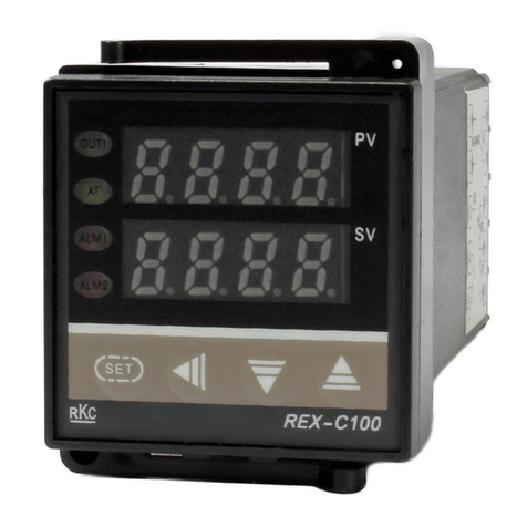
RKC INSTRUMENT REX - C100 Manual

RKC INSTRUMENT

RKC INSTRUMENT REX - C100 Manual

Popular Controllers manuals by other brands

Mitsubishi Electric MELSEC iQ-F Series manual

Mitsubishi Electric

Mitsubishi Electric MELSEC iQ-F Series manual

Watlow PM3 LEGACY quick start guide

Watlow

Watlow PM3 LEGACY quick start guide

Kelly KEB48200 user manual

Kelly

Kelly KEB48200 user manual

PLX Technology PEX 8648 White paper

PLX Technology

PLX Technology PEX 8648 White paper

National Instruments NI 8350 user manual

National Instruments

National Instruments NI 8350 user manual

NEC N8103-197 user guide

NEC

NEC N8103-197 user guide

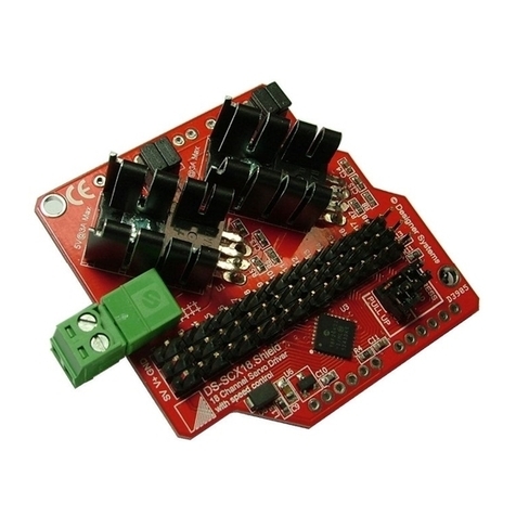
Designer Systems DS-SCX18.S manual

Designer Systems

Designer Systems DS-SCX18.S manual

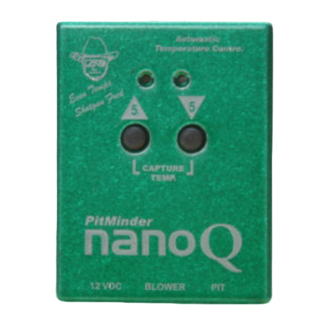
BBQ Guru Pitminder NanoQ II user guide

BBQ Guru

BBQ Guru Pitminder NanoQ II user guide

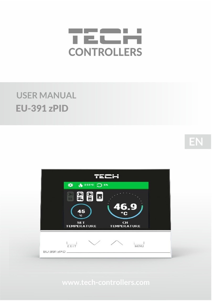
Tech Controllers EU-391 zPID user manual

Tech Controllers

Tech Controllers EU-391 zPID user manual

Integra DHC-9.9 instruction manual

Integra

Integra DHC-9.9 instruction manual

HomeMatic HM-LC-Sw1-PB-FM Installation and operating manual

HomeMatic

HomeMatic HM-LC-Sw1-PB-FM Installation and operating manual

Baumer SensControl operating manual

Baumer

Baumer SensControl operating manual

KMC Controls BAC-5900 Series installation guide

KMC Controls

KMC Controls BAC-5900 Series installation guide

KROHNE OPTISENS PAC 050 Installation and operating instructions

KROHNE

KROHNE OPTISENS PAC 050 Installation and operating instructions

SMOLKA MAX manual

SMOLKA

SMOLKA MAX manual

Vestamatic IF SMI KNX 230VAC 16 manual

Vestamatic

Vestamatic IF SMI KNX 230VAC 16 manual

Optec Gemini quick start guide

Optec

Optec Gemini quick start guide

Toptech MultiLoad II EXL installation guide

Toptech

Toptech MultiLoad II EXL installation guide

manuals.online logo
manuals.online logoBrands
  • About & Mission
  • Contact us
  • Privacy Policy
  • Terms and Conditions

Copyright 2025 Manuals.Online. All Rights Reserved.