Linvatec Hall Series 4 User manual
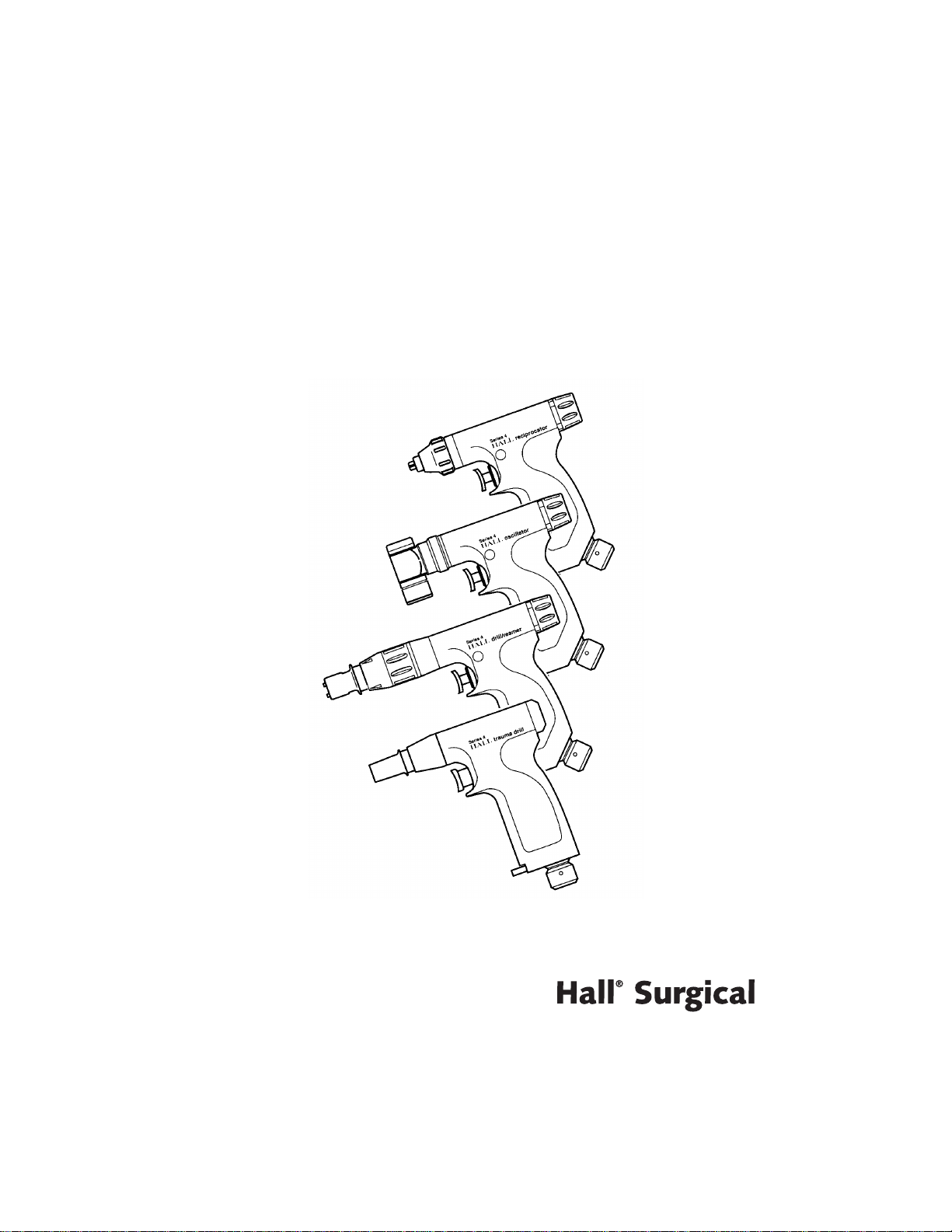
The Hall
®
Series 4
®
Instruction Manual

Proprietary Information
This manual contains information deemed proprietary to Linvatec Corporation. The
information contained herein, including all of the designs and related materials, is the sole
property of Linvatec and/or its licensors. Linvatec and/or its licensors reserve all patent,
copyright and other proprietary rights to this document, including all design, manufacturing
methodology and reproduction.
This document, and any related materials, is confidential and is protected by copyright laws
and shall not be duplicated, transmitted, transcribed, stored in a retrieval system, or
translated into any human or computer language in any form or by any means, electronic,
mechanical, magnetic, manual or otherwise, or disclosed to third parties, in whole or in part,
without the prior express written consent of Linvatec.
Linvatec reserves the right to revise this publication and to make changes from time to time in
the contents hereof without obligation to notify any person of such revision or changes, unless
otherwise required by law.
©
Linvatec Corporation 2000.All Rights Reserved. Printed in USA
Record the Model and Serial Numbers of the handpiece(s), and date received. Retain for
future reference.
Handpiece Model No. Serial No Date
Handpiece Model No. Serial No Date
Handpiece Model No. Serial No Date
Handpiece Model No. Serial No Date

Table of Contents Page
1
1.0 INTRODUCTION
1.1 Intended Use. . . . . . . . . . . . . . . . . . . . . . . . . . . . . . . . . . . . . . . . . . . . . . . . . . . . . . . . .3
1.2 General Warnings. . . . . . . . . . . . . . . . . . . . . . . . . . . . . . . . . . . . . . . . . . . . . . . . . . . . .3
2.0 INSTALLATION and OPERATION
2.1 Power Source and Regulator Installation and Operation . . . . . . . . . . . . . . . . . . . . . . .5
2.2 Equipment Installation and Operation . . . . . . . . . . . . . . . . . . . . . . . . . . . . . . . . . . . . .8
2.2.1 Drill/Reamer . . . . . . . . . . . . . . . . . . . . . . . . . . . . . . . . . . . . . . . . . . . . . . . . . .9
2.2.1.1 Connecting Attachments . . . . . . . . . . . . . . . . . . . . . . . . . . . . . . . .10
2.2.1.2 Mode Selection and Operation. . . . . . . . . . . . . . . . . . . . . . . . . . . .11
2.2.2 Oscillating Saw . . . . . . . . . . . . . . . . . . . . . . . . . . . . . . . . . . . . . . . . . . . . . . .12
2.2.2.1 Blade Attachment Instructions. . . . . . . . . . . . . . . . . . . . . . . . . . . .12
2.2.2.2 Rotating Head Instructions. . . . . . . . . . . . . . . . . . . . . . . . . . . . . . .14
2.2.2.3 Operating Instructions . . . . . . . . . . . . . . . . . . . . . . . . . . . . . . . . . .14
2.2.3 Reciprocating Saw. . . . . . . . . . . . . . . . . . . . . . . . . . . . . . . . . . . . . . . . . . . . .15
2.2.3.1 Blade Attachment and Operation Instructions. . . . . . . . . . . . . . . .15
2.2.4 Trauma Drill . . . . . . . . . . . . . . . . . . . . . . . . . . . . . . . . . . . . . . . . . . . . . . . . .17
2.2.4.1 Connecting Attachments . . . . . . . . . . . . . . . . . . . . . . . . . . . . . . . .17
2.2.4.2 Mode Selection and Activation . . . . . . . . . . . . . . . . . . . . . . . . . . .19

2
Table of Contents Page
3.0 MAINTENANCE
3.1 Cleaning and Sterilizing. . . . . . . . . . . . . . . . . . . . . . . . . . . . . . . . . . . . . . . . . . . . . . . 20
3.1.1 Care and Cleaning Precautions . . . . . . . . . . . . . . . . . . . . . . . . . . . . . . . . . . . 20
3.1.2 Cleaning Instructions. . . . . . . . . . . . . . . . . . . . . . . . . . . . . . . . . . . . . . . . . . . 20
3.1.3 Sterilization . . . . . . . . . . . . . . . . . . . . . . . . . . . . . . . . . . . . . . . . . . . . . . . . . . 21
3.1.3.1 Pre-Vacuum Steam Sterilization . . . . . . . . . . . . . . . . . . . . . . . . . . 22
3.1.3.2 Gravity Air Displacement Steam Sterilization . . . . . . . . . . . . . . . 22
3.2 Troubleshooting . . . . . . . . . . . . . . . . . . . . . . . . . . . . . . . . . . . . . . . . . . . . . . . . . . . . . 23
3.3 Specifications . . . . . . . . . . . . . . . . . . . . . . . . . . . . . . . . . . . . . . . . . . . . . . . . . . . . . . . 27
3.3.1 Drill/Reamer Handpiece . . . . . . . . . . . . . . . . . . . . . . . . . . . . . . . . . . . . . . . . 27
3.3.2 Trauma Drill Handpiece . . . . . . . . . . . . . . . . . . . . . . . . . . . . . . . . . . . . . . . . 27
3.3.3 Oscillating Saw . . . . . . . . . . . . . . . . . . . . . . . . . . . . . . . . . . . . . . . . . . . . . . . 28
3.3.4 Reciprocating Saw. . . . . . . . . . . . . . . . . . . . . . . . . . . . . . . . . . . . . . . . . . . . . 28
3.3.5 Environmental Requirements . . . . . . . . . . . . . . . . . . . . . . . . . . . . . . . . . . . . 29
4.0 CUSTOMER SERVICE and WARRANTY
4.1 Customer Service . . . . . . . . . . . . . . . . . . . . . . . . . . . . . . . . . . . . . . . . . . . . . . . . . . . . 30
4.2 Attachments and Accessories. . . . . . . . . . . . . . . . . . . . . . . . . . . . . . . . . . . . . . . . . . . 32
4.3 Linvatec and Hall
®
Surgical Instrument Warranty . . . . . . . . . . . . . . . . . . . . . . . . . . 34

3
1.0
INTRODUCTION
It is recommended that personnel study this
manual before attempting to operate, clean or
sterilize the Hall
®
Series 4
®
Handpieces. The
safe and effective use of this equipment requires
the understanding of and compliance with all
warnings, caution notices and instructions
marked on the product and included in this
manual.
1.1 Intended Use
The intended use for the Hall Series 4 hand-
pieces is in large bone surgery.
1.2 GeneralWarnings
1. This equipment is designed for use only by
medical professionals who are completely
familiar with the required techniques and
instructions for use of the equipment. Read
and follow all warnings and caution notices
and instructions marked on the product and
included in this manual.
2. Eye protection is recommended
when operating equipment.
3. Use only Linvatec
®
and Hall
®
accessories
and attachments.
4. Prior to each use, perform the following:
• Inspect all equipment for proper
operation.
• Ensure all attachments, accessories and
hoses are correctly and completely
attached to the handpiece.
• Always inspect hoses for signs of wear
or damage. Do not use worn or
damaged hoses. Replace immediately.
• Check all equipment for any air or
nitrogen leakage. If leakage is noticed,
return for service.
5. Handle all equipment carefully. Should a
handpiece or attachment be dropped or
damaged in any way, return it immediately
for service.
6. Put the instrument in the “SAFE” position
before changing blades, bits, accessories or
hoses, and when the instrument is not in
use. Accidental activation of the instrument
could cause injury.

4
7. Always inspect for bent, dull or damaged
blades or drill bits before each use. Do not
attempt to straighten or sharpen. After use,
dispose of properly.
8. Dull bits and blades may cause heat build-
up in the handpiece and the bone. It is
recommended that single-use bits and
blades be used. If reusable bits or blades are
used, inspection with a magnifying glass
should be performed to check for dulled
and chipped cutting surfaces.
9. Continually check all parts of the
instrument or its attachments for
overheating. If overheating is noticed,
discontinue use and return the equipment
for service.
10. Do not pressurize hoses until all fittings
have been connected and checked.
11. Never operate instrument above 100 psi
(7 kg/cm
2
) dynamic pressure unless an
extension hose is added to the standard 10
foot hose. Excessive pressure may cause
damage to instrument and exert unusual
stress on the hose.
12. Use the appropriate mode selection for the
appropriate function.
• Never drive bone screws with the Drill/
Reamer in the “REAM” or “DRILL”
position.
• Always use the “SCREW” position for
tapping threads and seating screws.
13. The nitrogen regulator is for use with
pneumatically powered surgical devices
only.
14. Do not lubricate any Series 4 handpiece or
accessory.
15. After each use, thoroughly clean and
sterilize handpieces and accessories (See
“Cleaning and Sterilizing” on page 20
).
5
2.0
INSTALLATION and
OPERATION
2.1 Power Source and Regulator
Installation and Operation
WARNING: Not for inhalation. Does not
support life. For use with powered surgical
devices only.
Research and experience have shown that water-
pumped dry nitrogen is the ideal source for
pneumatically-powered surgical instruments.
Water-pumped dry nitrogen is 99.97% pure, and
will not support combustion or corrosion.
Compressed dry nitrogen is recommended as the
pneumatic power source. It is available in
standard cylinders.
Compressed dry nitrogen must meet the
following specifications to ensure optimum
safety for both patient and instrument.
Nitrogen Content:
99.97% pure, dry nitrogen.
QualityAssurance:
To obtain the quality of gas
needed, “water-pumped dry nitrogen, or liquid
nitrogen, pumped dry” should be specified.
Nitrogen is readily available from gas supply
houses in
H
cylinders holding slightly more than
300 cubic feet (8.50 cubic meters). Initial set-up
costs are relatively inexpensive as compared to
compressed air. Nitrogen can be placed in the
operating room or in a storage area and piped
into the operating room. Manifold systems are
available to eliminate frequent tank changes.
CAUTION: Do not exceed 100 psi
(7 kg/cm
2
) operating pressure unless a hose
longer than the standard 10 ft. Universal
Hose (5052-010) or extension hose is used.
Add an additional 1 psi for every extra foot of
hose.
The Series 4 handpieces should be operated
at 100 psi (7 kg/cm
2
) for maximum operating
efficiency, and should be monitored by the
operating pressure gauge of the regulator.
Lower pressure setting can be set for lower
speed and torque requirements. Pressure
must be set with the instrument running to
ensure proper operating pressure.
Never start a procedure if the operating
pressure gauge indicates less than 500 psi
(35.1 kg/cm
2
) in the tank. Never run the tank
pressure below 200 psi (14.0 kg/cm
2
).
The tank should be thoroughly wiped off with
disinfectant and draped prior to placement in
the operating room.Always have the tank
securely fastened to a stable object.
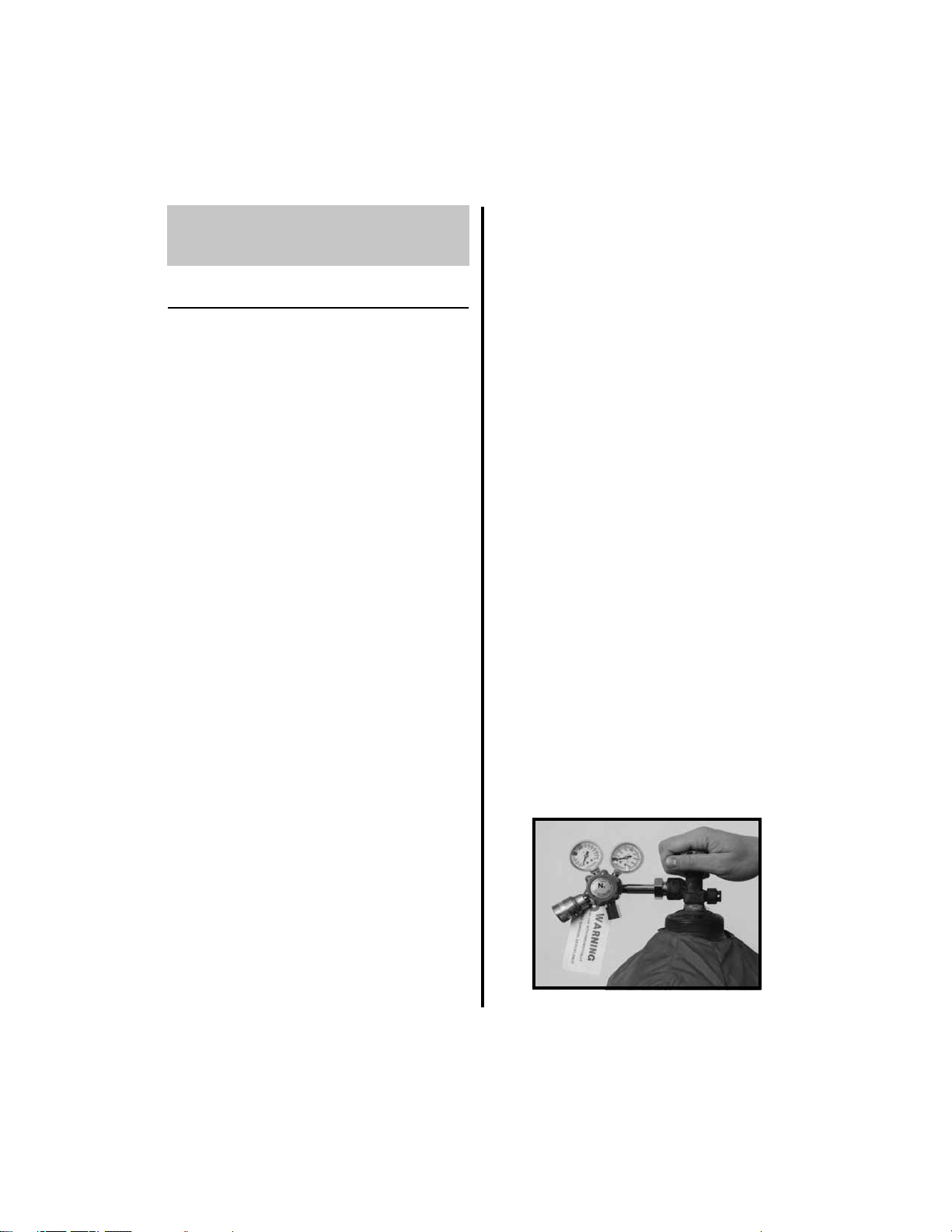
1. Prior to set-up in the operating room, open
the tank valve (counterclockwise) slowly
and allow enough gas to escape to blow out
any debris that may have accumulated in
the valve. Stay clear of the opening and the
back of the tank during this procedure.
Return the valve to the closed position.
6
2. Install the regulator with a 1 1/8 inch
wrench.
NOTE: The threaded adaptor of the
nitrogen regulator is designed to fit nitrogen
fittings only. Incompatibility of the regulator
and tank indicates a gas source other than
nitrogen or an improper regulator for use
with a nitrogen tank.
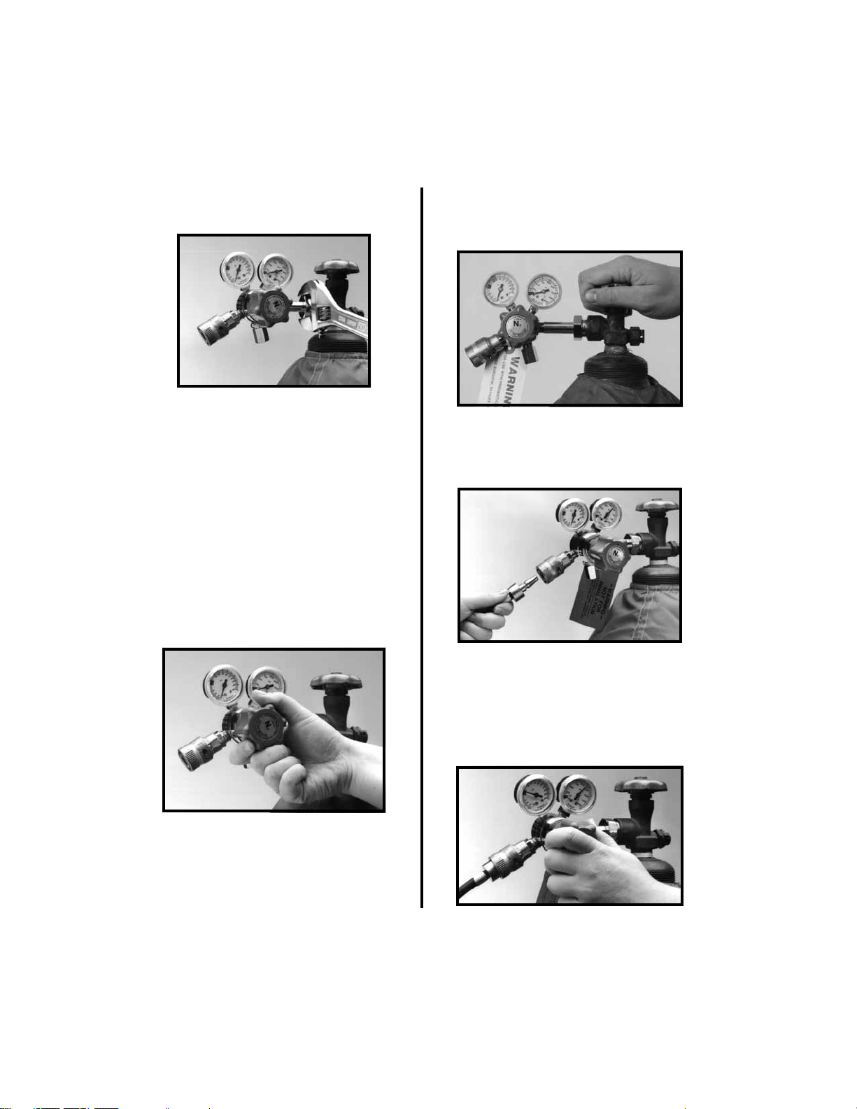
3. Once the regulator is securely installed,
ensure the regulator knob is in the full off
position by turning the regulator control
knob counterclockwise.
SUDDEN
PRESSURE EXERTED TO THE
REGULATOR MAY CAUSE
INTERNAL DAMAGE.
4. Slowly turn the tank valve fully open
(counterclockwise). This will allow
nitrogen to pressurize the regulator.
5. Insert the male Schrader end of the hose
into the female Schrader on the regulator
with an upward thrust.
6. Operating pressure is established by
gradually turning the regulator control knob
clockwise.
ALWAYS establish the
designated pressure on the operating
pressure gauge with the instrument
running.

7
7. Before removing the instrument from the
regulator:
(a) Close the tank valve by turning it
clockwise.
(b) Activate the instrument to bleed off
line pressure.
(c) Turn the pressure regulator knob
counterclockwise until it stops.
(d) Turn the female Schrader to the right to
disengage the male Schrader fitting.
(e) The hose can then be removed from the
connector. Hold the end of the hose
securely when disengaging the male
Schrader fitting to prevent possible
damage to the diffuser.
8. If the Hall Pneumatic Connector* is being
used:
(a) Locate the button marked “PRESS”.
(b) Depress and hold the button until the
audible release of residual gas is
completed.
(c) Release the button and remove the
hose.
(d) If the hose cannot be easily removed,
depress the “PRESS” button again,
release it and remove the hose.
* U.S. Patent 4,863,201

8
2.2 Equipment Installation
and Operation
1. Place the handpiece in the “SAFE”
position.
2. To connect the handpiece to the hose.
(a) Insert the coupling end of the hose into
the fitting on the bottom of the
handpiece.
(b) Twist the hose coupling to the right
(clockwise) and slightly pull on the
hose so the internal pins securely
engage in the indentations.
3. Attached to the Universal Hose (5052-010)
is the Hall Hose Handler*. This clip allows
fixation of the hose to the surgical drape,
reducing the problem of the hose slipping
off the patient.
4. The Velcro
®
strap allows the hose to be
coiled, thus reducing excess hose length. In
addition, the VELCRO strap may be used
with any additional hose and/or cable.
* U.S. Patent 4,639,980

9
2.2.1 Drill/Reamer
❶
Mode Selector -
Used to select the
operating mode of the handpiece between
“DRILL” “SCREW” and “REAM”.
“DRILL” Position:
Used for Drilling and
Pin Insertion.
“REAM” Position:
Used for Femoral
Reaming, Acetabular Reaming and Pin
Insertion.
“SCREW” Position:
Used for Tapping and
Setting Bone Screws.
❷
Direction Control Knob -
Used to select
the operating direction between “FWD”
(forward) “REV” (reverse) and “SAFE”.
Place the control knob in the “SAFE”
position when changing accessories. To
activate the handpiece, place the control
knob in either “FWD” or “REV”.
❸
Activation Trigger -
Used to activate the
handpiece when the direction control knob
is in either “FWD” or “REV”.
❹
Zimmer/Hudson Snap-Lock Chuck -
Used to quickly attach accessories.
❶❷
❸
❹

10
2.2.1.1 Connecting Attachments
The Drill/Reamer Handpiece has a combination
collet which will accept all the illustrated shank
styles below, without the need for an adaptor.
AO shanked products (not pictured) may also be
used with the Drill/Reamer Handpiece, utilizing
the Zimmer to AO Adaptor.
Trinkle shank accessories must utilize the
Zimmer to Trinkle adaptor. Affix the Trinkle
adaptor into the Zimmer/Hudson snap-lock
chuck as described in step 1.
AO Shank accessories must utilize the AO
adaptor. Affix theAO adaptor into the Zimmer/
Hudson snap-lock chuck as described in step 1.
1. To connect attachments:
(a) Place the Direction Control Knob in
the “SAFE” position.
(b) Firmly grasp the chuck and pull back
toward the handpiece.
When inserting Trinkle or AO
products, care should be taken to pull
back on the adaptor itself, not the
handpiece snap-lock chuck.
(c) Insert the shank of the attachment into
the chuck, then release the chuck.
NOTE: Be certain the Trinkle or AO
Adapter is properly seated. When properly
affixed, the inner housing will be flush with
the outer housing.

11
The Drill/Reamer is cannulated and will accept
pins up to 0.156 inch diameter or 4.0mm.
2. To attach the Torque Control Handle to the
instrument:
(a) Insert the handle into the torque control
receptacle on the side of the handpiece.
(b) Twist the Torque Control Handle until
it locks securely into position.
3. The Torque Control handle is easily
removed by twisting and pulling out on the
handle.
NOTE: Securely attach the torque control
handle when using heavy reamers or
attachments. The torque control handle will
assure maximum control of the handpiece.
2.2.1.2 Mode Selection and Operation
WARNINGS:
1. Always make sure you are in the proper
mode before the handpiece is activated.
2. Never set bone screws with the handpiece
in the “REAM” position. Only use the
“SCREW” position for setting bone
screws.
1. Twist the mode selector ring until the arrow
is aligned with the arrow on the handpiece
for the desired position.
2. Twist the direction control knob from
“SAFE” to the desired operating direction
(“FWD” or “REV”).
3. Depress the trigger to activate the
handpiece.

12
2.2.2 Oscillating Saw
❶
Control Knob -
Place this knob in the
“ON” position to activate the handpiece.
Place in the “SAFE” position before
changing blades, bits, accessories or hoses,
and when the instrument is not in use.
❷
Head Locking Collar -
Allows the rotating
head to be rotated and locked in any of 12
positions.
❸
Rotating Head -
Houses the cutting blade
and rotates to any of 12 positions at 30°
intervals for appropriate surgical access.
❹
Blade Locking Collet -
Holds the blade in
place.
❺
Blade Locking Knob -
Locks the blade
securely in place.
❻
Activation Trigger -
Press to operate the
handpiece when the control knob is in the
“ON” position.
2.2.2.1 Blade Attachment Instructions
1. To affix a blade to the blade-locking collet*:
(a) Place the control knob in the “SAFE”
position.
* U.S. Patent 5,265,343
❶❷
❸
❹
❺
❻

13
(b) Open the blade-locking collet by
rotating the blade-locking knob in the
direction of the arrow to the “OPEN”
position.
(c) Insert the blade at the desired angle and
align the blade holes with the blade-
positioning pins. Be sure that the
proper saw blades are used with the
collet. Micro Sagittal Saw Blades may
not be used in the wrenchless collet,
only Hall series 5071-xxx blades can
be used.
(d) Rotate the blade locking knob to the
closed position.

14
2.2.2.2 Rotating Head Instructions
1. The rotating head may be set in any of 12
positions at 30˚ intervals for appropriate
surgical access. To change positions and
cutting planes:
(a) Grasp the head locking collar firmly
and pull towards the back of the
handpiece.
(b) Rotate the head and blade to the
desired position. Release the head
locking collar.
2.2.2.3 Operating Instructions
1. To operate the handpiece:
(a) Twist the control knob from the
“SAFE” position to the “ON” position:
(b) Depress the activation trigger.
15
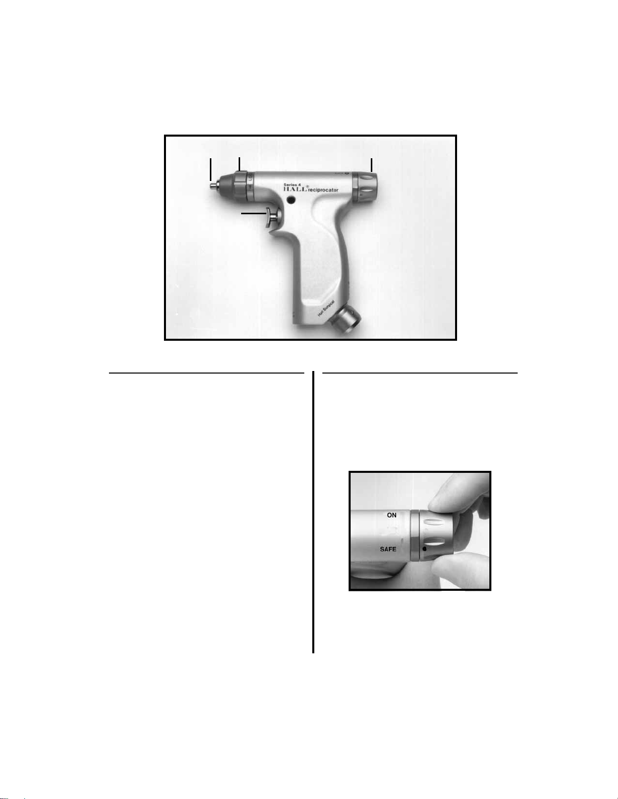
2.2.3 Reciprocating Saw
❶
Blade Collet -
Holds the blade in place.
❷
Collet Locking Knob -
Used to lock the
blade collet.
❸
Control Knob -
Place this knob in the
“ON” position to activate the handpiece.
Place in the “SAFE” position before
changing blades, bits, accessories or hoses,
and when the instrument is not in use.
❹
Activation Trigger -
Press to operate the
handpiece when the control knob is in the
“ON” position.
2.2.3.1 Blade Attachment and
Operation Instructions
1. To affix a blade to the handpiece:
(a) Place the control knob in the “SAFE”
position.
❶ ❸❷
❹

16
(b) Open the blade collet by turning the
collet locking knob clockwise for
adequate blade width.
(c) Insert the shank of the blade into the
slot and seat completely.
(d) Blades may be locked in any position.
Four (4) detents are provided for
accurate 90˚ positioning. Before
locking the collet, grasp the blade at
the base of the collet and turn to the
desired position.
(e) Turn the collet locking knob counter-
clockwise to firmly secure the blade.
2. To operate the handpiece:
(a) Twist the control knob from the
“SAFE” position to the “ON” position.
(b) Depress the activation trigger.

17
2.2.4 Trauma Drill
❶
CombinationTrinkle/AO Collet -
Accepts
the various Trinkle and AO shank
accessories.
❷
Safety/Activation Trigger -
Rotate either
left or right to the “SAFE” position when
attaching/removing attachments,
accessories and hoses. Rotate to the vertical
position to activate the handpiece.
❸
Direction Control Lever -
Used to select
the operating direction between “FWD”
(forward) “SCREW” and “REV” (reverse).
2.2.4.1 Connecting Attachments
1. Place handpiece in the “SAFE” position.
(a) Rotate the trigger either left or right.
Attachment of Trinkle Shank Accessories:
1. Pull back the outer collet sleeve.
2. Insert the Trinkle shank into the collet. The
spring-loaded inner sleeve will retract.
❶
❸
❷
18
3. Release the collet sleeve.
4. Once the shank has been totally inserted,
rotate the accessory until it becomes
completely engaged. Pull the accessory
firmly to ensure proper engagement.
5. To remove the accessory, pull back the
outer sleeve and pull the accessory out.
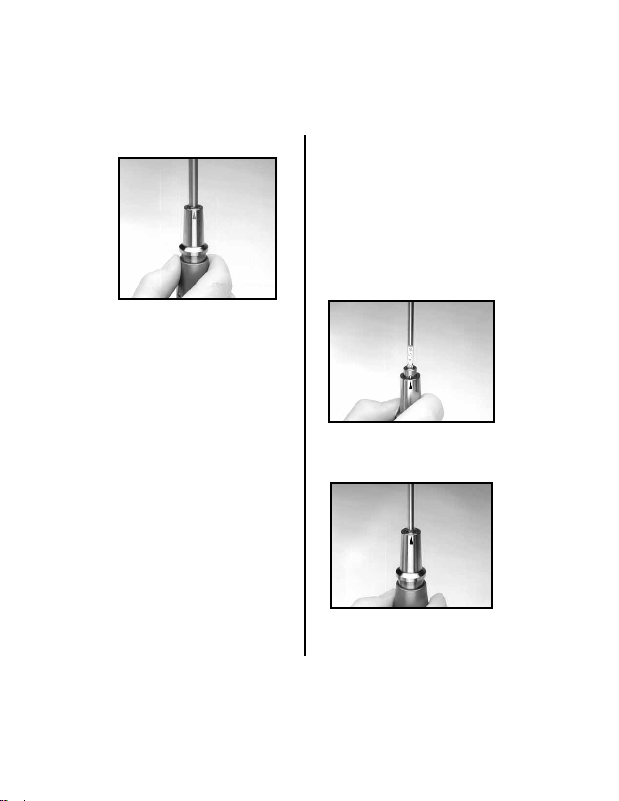
Attachment of AO Drill Accessories:
1. Align the flat portion of the accessory shank
with the black arrow on the collet sleeve,
and insert the accessory into the collet.
2. Insert the shank as far as it will go without
pulling back the collet sleeve. Twist the
shank to make sure it is aligned properly. If
it is, it will not spin in the collet.
3. Pull back on the collet sleeve while pushing
the shank further into the collet.
4. Release the collet sleeve. The shank is now
locked into the collet. Pull the accessory
firmly to ensure proper engagement.
5. To remove the accessory, pull back the
outer sleeve and pull the accessory out.
Table of contents
Popular Medical Equipment manuals by other brands

Tecnimed
Tecnimed Ecosave instructions

Cardinal Health
Cardinal Health NPWT PRO Clinician Quick Reference Guide

Lowenstein Medical
Lowenstein Medical NV Instructions for use

Dentsply Sirona
Dentsply Sirona X-Smart IQ Directions for use

argon audio
argon audio SuperCore Instructions for use

Accutome
Accutome B-Scan Plus user guide


