MELAG MELAtherm 10 User manual

Dear Dr.
We should like to extend our thanks for the expression of trust in our company which you have displayed through the
purchase of this MELAG product.
As an owner-run and operated family concern founded in 1951, we have a long history of successful specialization in
hygiene products for practice-based use. Our focus on innovation, quality and the highest standards of operational
reliability has established MELAG as the world’s leading manufacturer in the instrument treatment and hygiene field.
You, our customer are justified in your demand for the best products, quality and reliability. Providing "competence in
hygiene" and "Quality –made in Germany", we guarantee that these demands will be met. Our certified quality
management systems is subject to close monitoring: one instrument to this end is our annual multi-day audit conducted
in accordance with ISO 13485 and ISO 9001. This guarantees that all MELAG products are manufactured and tested in
accordance with strict quality criteria.
The MELAG management and team.
User Manual
MELAtherm®10
Washer-Disinfector
Software version 1.309

General Guidelines
Please read this User Manual before you start operation of the device. The manual contains important safety information.
The functionality and value-retention of this autoclave depend on the care accorded to it.
Make sure to keep the User Manual close to the device. It represents a component of the product.
User Group
This manual is targeted at doctors, medical assistants and service.
Validity
This manual applies to the devices MELAtherm 10 DTA and MELAtherm 10 DTB.
About these Instructions
Symbols used
Symbol
Explanation
Indicates a dangerous situation which if not avoided could entail slight to life-threatening
injuries.
Indicates a dangerous situation which if not avoided could entail damage to the
instruments, the practice equipment or the device.
Draws your attention to important information.
Marking rules
Symbol
Explanation
→HEPA filter
Words or phrases marked with an arrow are explained in the glossary. The glossary is
listed alphabetically. It can be found at the end of this manual.
Cleaning
Words or phrases appearing on the display of the device are marked as display text.
see Chapter 2
Reference to another text section or a figure within this manual.
Symbols on the device
Symbol
Explanation
In affixing the CE mark, the manufacturer declares that this medical product fulfils the
basic requirements of the medical products directive. The four-digit number confirms that
this is monitored by an approved certification agency.
The symbol of the crossed out waste bin identifies a device that must not be disposed in
domestic waste. The vendor is responsible for proper and professional disposal.
By the designation of an apparatus with this symbol, the manufacturer furthermore
declares that he satisfies all requirements of the law concerning the release, redemption
and environmentally sound disposal of electric and electronic appliances.
Disposal
The packaging protects the device against transport damage. The packaging materials have been selected for their
environmentally-friendly and recycling properties and can be recycled. Returning the packaging to the material flow
reduces the amount of waste and saves raw materials. Dispose of all non-required packaging materials at the collection
points of the dual system.
Dispose of waste from process agents in accordance with the specifications from the manufacturer of the process
agents. Information regarding this topic is provided by the safety data sheets or can be obtained directly from the
manufacturer of the process agents.
Dispose of accessories and consumption media which you no longer require (e.g. used filters) in the appropriate manner.
Comply with all relevant disposal specification in terms of possibly contaminated waste.

Contents
Contents
Chapter 1 –Performance Specifications.........6
Proper use................................................................... 6
User benefits ............................................................... 6
Chapter 2 –Device Description.......................8
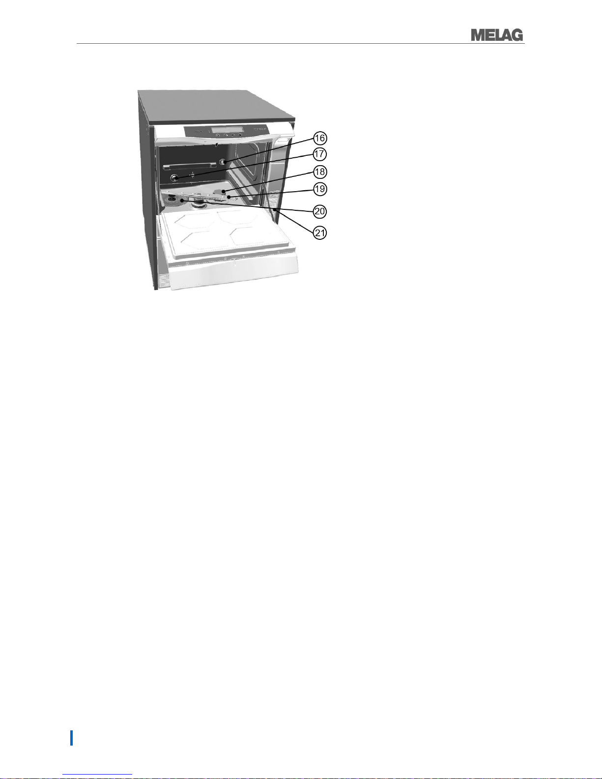
Views of the device...................................................... 9
The control panel........................................................11
Acoustic signals..........................................................11
Overview of menus.....................................................12
Automatic door lock....................................................13
Emergency release.....................................................13
Water softening unit....................................................14
Chapter 3 –Initial Commissioning.................15
Conditions for setting up, installing and starting up ....15
Requirements to the set-up location...........................15
Set-up variations.........................................................16
Space requirements....................................................16
Connections required..................................................17
Filling the regeneration salt.........................................17
Regeneration..............................................................18
Process agents...........................................................18
Filling the cleaning agent............................................19
Filling the neutralizer...................................................19
Filling the rinse aid......................................................20
Bleeding the metering hoses ......................................20
Metering......................................................................21
Switching on the device..............................................21
Preconditions for commissioning................................21
Record of installation and setting up...........................21
Chapter 4 –Cleaning and Disinfection..........22
The nature of the load.................................................22
Hollow bodied instruments..........................................22
Dental transfer instruments.........................................23
Ophthalmologic instruments.......................................23
Arranging the load......................................................25
Observe before the program start...............................26
Closing the door .........................................................26
Selecting the program.................................................26
Starting the program...................................................27
Program run................................................................27
Program ended...........................................................28
Manual program termination.......................................29
Removing the load......................................................30
Chapter 5 –Logging.....................................31
Batch documentation .................................................31
Using the CF card as an output medium....................32
Computer as output medium......................................33
Log printer as issue medium......................................33
Automatic immediate log output.................................34
Output the logs subsequently.....................................35
Determining the format for the program log ...............35
Finding Logs ..............................................................39
Chapter 6 –Settings.....................................40
Opening the setup menu............................................40
Water supply..............................................................40
Automatic logging.......................................................41
Date and time.............................................................41
Display contrast .........................................................42
Language...................................................................43
Water hardness..........................................................43
Chapter 7 –Function Test............................44
Automatic function test...............................................44
Manual function test...................................................44
Testing in daily operation...........................................44
Measuring conductivity...............................................44
Chapter 8 –Maintenance .............................45
Daily inspection/cleaning............................................45
Cleaning on demand..................................................46
Changing the HEPA filter in the drying fan.................47
Avoid formation of spots.............................................48
Maintenance ..............................................................48
(Process) validation....................................................48
Chapter 9 –Operating Pauses .....................49
Pause times ...............................................................49
Shut-down..................................................................49
Transport....................................................................49
Re-commissioning after change of locality.................50
Chapter 10 –Errors......................................51
Before you call ...........................................................51
Appendix A - Accessories.............................57
Technical Data .............................................58
Glossary.......................................................60

Chapter 1 –Performance Specifications
4
Safety Instructions
When operating the device, please ensure that you observe the following safety instructions as well as
those contained in the following chapters.
Purpose
Use the device only for the purpose named in the user manual.
Power cable and mains socket
All legal specifications and electrical operating conditions of the local electricity provider must be
complied with completely.
Never damage or alter the plug or mains cable.
Never operate the device if the mains cable or power plugs are damaged.
Never unplug by pulling on the power cable. Always grip the plug itself.
Set-up installation and commissioning
Only have the device set up, installed, and started up by people →authorised by MELAG.
Check the device for any damage suffered during transport after unpacking.
Only operate the device in areas that are not subject to explosion hazards.
The connections for electrical provision and water supply and discharge must be set-up by trained
personnel.
Documentation media (computer, CF card reader, etc.) must be placed in such a way that they
cannot come into contact with liquids.
Daily operation
Use only those instruments designed by their manufacturer for automatic treatment in a washer
disinfector. Please ensure that you observe the information provided by the instrument
manufacturers according to ISO 17664. It is especially important to observe the manufacturer's
information when treating newly purchased instruments for the first time.
Use only original MELAG accessories or those from other suppliers authorized for use by
MELAG.
When using additional accessories to accept instruments, especially hollow-bodied instruments, it
is necessary to observe the information contained in the manufacturer's operating instructions.
Observe the relevant standards and directives applicable to the treatment of instruments e.g. from
the →RKI, →BfArM, →DGSV, →DGKH etc. as well as the treatment information from the
instrument manufacturer and the →AKI.
The personnel responsible for instrument treatment must be sufficiently trained and schooled.
The fore ventilation slits must not be covered.
Only operate the device with the basis basket provided for this purpose.
Process agents
Handle all process agents with care. The cleaning, neutralization and rinsing aids contain irritants
and even caustic substances.
Use only those process agents cleared for use in a washer-disinfector and which MELAG has
approved for use in this device. Observe the operating and safety information of the process
agent manufacturer. If, despite observation of the manufacturer's information, the process agents
have a negative effect on the material of the instruments or the device, liability lies with the
manufacturer of the process agents.
The use of process agents not approved by MELAG absolves MELAG of all liability whatsoever
for any damage to the device or the instruments.
Should you have any questions concerning the compatibility of the process agents with the
instruments, please consult the manufacturer. MELAG provides information for the application of
the process agents in the device but does not take any responsibility for their effects on the
instruments.
Any fluids in the drawer and the floor tank underneath can also contain process agents in case of
damage. Ensure that you observe the information of the respective process agent manufacturer.
Maintenance
Have the maintenance performed only by →authorised persons.

Chapter 1 –Performance Specifications
5
Transport and storage
Install and operate the device in a frost-free environment. Store and transport the device in a
generally frost-free environment.
Avoid strong shocks.
The device should always be carried by two people.
Malfunctions
If repeated error messages occur while operating the device, turn the device off and notify your
specialist dealer.
Only have the device repaired by →authorised persons.

Chapter 1 –Performance Specifications
6
Chapter 1 –Performance Specifications
In this chapter you learn
The purpose for which you can employ the device
What benefit you can achieve by using it
The cleaning programs that are available
Proper use
This device is designed for application in a medical context, e.g. clinics and medical and dental practices.
In accordance with DIN EN ISO 15883-1 and -2, this device is a washer-disinfector. You can subject
thermo-stable medical instruments (i.e. instruments which are heat resistant to a temperature of 95 °C) to
automatic cleaning as long as they are suitable for this purpose.
The cleaning is undertaken via the use of water and a chemical cleaning agent.
Subsequent disinfection is performed by thermal disinfection.
This device is not suitable for treatment of:
Thermo-instable instruments, e.g. flexible endoscopes
Wastes for disposal and in the lab area
Dishes
Bedpans
User benefits
Universal use
The device cleans and disinfects. The disinfection phase is conceived so as to reach an A0 value of at
least 3000. This eliminates vegetative bacteria and fungi/fungal spores and disables viruses (inc. HBV,
HCV) thus reaching the effective range AB according to the RKI directive.
Active drying
The device has an active drying facility. This means that after cleaning and disinfection, the instruments
are dried inside (interior lumen) and out via an integrated drying fan. This enables the automatic treatment
of hollow-bodied instruments such as suction cannulas. This protects the instruments from stain accretion
and rusting.
The additionally fitted →HEPA filter guarantees drying with →contamination-free air.
The geometry of some hollow-bodied instruments such as turbines requires additional drying.
Automatic filter recognition
The device recognizes automatically that the fine filter has not been inserted in the base of the washing
chamber before starting. Thus it avoids a situation in which instrument components enter the opening of
the outflow pump or the circulation pump and thus restricting the function of the pumps, rinse arms and the
injector rails.
Internal water softening
The device has an internal softening plant. The water hardness of the local drinking water is set in the
device. The internal water softening unit then automatically adjusts itself to the best solution. This ensures
the optimal rinsing of chlorides.
Monitoring the rotation speed of the rinse arms
The rotation speed of the lower and upper rinse arms is subject to permanent monitoring during a program
run. This ensures that the cleaning process proceeds without hindrance and the rinse arms do not become
blocked e.g. by protruding instruments in the washing chamber.
Monitoring cleaning pressure
The cleaning pressure is monitored during a program run via a pressure sensor. This ensures effective
cleaning. Excess foam generation results in the interruption of the program run.

7
Metering monitoring
The required amounts of cleaning agent and neutralizer are measured out using a hose measuring pump.
A measurement turbine performs flow monitoring. The rinse aid is metered using a hose metering pump
subject to monitoring for rotation speed.
Drawer for process agents
The drawer in the lower area of the device provides storage space for the process agents cleaning agent,
neutralizer and rinse aid.
Automatic conductivity measurement
If the device is provided with DI water in the final rinse, the DI water is subject to automatic, internal
conductivity measurement.
CF card, Ethernet
An integrated CF card slot and Ethernet interface enable secure and easy documentation of the entire
cleaning and disinfection process. This is an important precondition for the clearance process. This
enables the transfer of data from the device to your practice computer.
Display
A program can be started and settings undertaken via the two-line display with four operating keys.
Motorized door lock
The device is equipped with a comfortable locking mechanism which locks the door with an automatic door
lock with a motorized lock.
Emergency release
The door can be opened manually in the case of a loss of power or malfunction using the emergency
release.

Chapter 2 –Device Description
8
Chapter 2 –Device Description
In this chapter you learn
Which components are included in the scope of delivery
What components the device contains
What safety devices the device has
How the operating elements are designed and how you should use them
Scope of delivery
Standard scope of delivery
Washer-disinfector MELAtherm 10
User Manual
Technical Manual
Record of installation and setting up
Declaration of conformity
1 Container, 5 l
1 container for rinse aid, 1 l
1 feed funnel for the regeneration salt
1 starter package of regeneration salt
Optionally
Stainless steel cover plate (HxWxD 1.8 cm x 59.8 cm x 59.8 cm)
Floor unit (HxWxD 40 cm x 59.8 cm x 49.8 cm)
Accessories
According to order

9
Views of the device
Front side
1. Cover plate (optional)
2. Operating and display field
3. Mains switch
4. Cover for CF card slot and Ethernet data
interface
5. Door handle
6. Door, can be opened forwards
7. Drawer handle
8. Drawer for process agents, can be pulled
out
9. Device front feet
Back side
10. Ethernet-Data connection (rear)
11. Mains power cable
12. Connection for de-ionised water
(DI water)
13. Connection for cold water (CW)
14. Effluent connection
15. Transport rollers
Fig. 1: Views of the device

Chapter 2 –Device Description
10
Interior view
16. Connection tube for injector rails
17. Water intake cold water (CW) + DI water
18. Salt container
19. Rinse arm
20. Coarse and fine filter
21. Cooling slot (air outlet with active drying)
Fig. 2: Interior view

11
The control panel
The control panel consists of a two-line alphanumerical LED display and four membrane keys.
Keys 1234
Key
When to be used?
Function/Explanation
e.g. program
selection
Takes precedence over navigation BACKWARDS - FORWARDS,
to adjust a value: SMALLER - LARGER
To unlock the door or
BACKWARDS, CANCEL, leave menu
ENTER, OK, YES, SELECT, QUIT upon warning or error message
In all display images
The system status is constantly displayed in 8 further display
images with information relating to the device e.g. serial number,
software version, daily and total batches etc.
after program
interruption
QUIT + DOOR, i.e. to clear the program interruption and
unlock the door
in the DOCU menu
To delete all logs located in the internal log memory
In Universal-Program
Only for technicians (validation mode)
Only for technicians (maintenance mode)
Acoustic signals
The device emits acoustic signals. The signals are designed to attract your attention and serve to inform
the operator. With consecutive signals, the time between two signals amounts to 0.5 seconds.
Signal
Meaning
1 x 0.1 Seconds
Confirms the correct operation of a key
1 x 0.5 Seconds
Warning or message
3 x 0.5 Seconds
At indication: Refill the salt soon;
Program interruption; end of interruption reached after interruption of drying
5 x 0.5 Seconds
Program completed successfully
10 x 0.5 Seconds
Fault

Chapter 2 –Device Description
12
Overview of menus
MAIN MENU
├
P01 Universal-Program
├
P02 Quick-Program
├
P03 Intensive-Program
├
P04 Ophthalmo-Program:
├
Z01 Rinsing
├
Z02 Emptying
├
Z03 Reference value measurement DI
├
Z04 Air removal
├
Z05 Regeneration
├
Z06 Time metering 60s
├
M01 DOCU MENU (Output of a saved log via the following output media)
│
└
Select output medium Automatic*, CF card, MELAprint, PC
│
├
01 Log list
│
├
02 Last log
│
├
03 Logs of day
│
├
04 Logs of week
│
├
05 Logs of month
│
├
06 All logs
│
├
07 Last malfunction log
│
├
08 Malfunction logs of day
│
├
08 Malfunction logs of week
│
├
10 Malfunction logs of month
│
├
11 All malfunction logs
│
├
12 Caption log
│
├
12 Status log
│
├
14 System log
│
└
15 Format CF card
└
M02 SETUP- MENU
├
01 DI water
├
02 Automatic logging
│
└
├
03 Date
├
04 Time
├
05 Display contrast
├
06 Language
├
07 Water (hardness) °dH
└
08 DIAGNOSIS + SERVICE
├
> AC outputs (AC-OUT)
├
> DC outputs (DC-OUT)
├
> Analogue inputs
├
> Counter inputs
├
> Digital inputs
│
SERVICE MENU
│
└
├
Maintenance Counter Date
└
DEMO mode

13
Automatic door lock
The automatic door lock guarantees the safe locking and sealing of the door during the program run. The
door is locked by a motorized lock. The device must be connected to the mains and switched on in order
to open and close the door.
1. In order to close the door of the device, raise the door and press it on firmly until it clicks. You can
let go of the door as soon as the motorized lock activates.
The door is then closed and locked automatically.
2. To open the door, press the key. This unlocks the door which now can be opened. Pull the
door forward using its handle.
NOTE
After the program has begun, the door can only be opened by interrupting the program. Clearing
the program interruption or the end of a program also opens the door.
Emergency release
DANGER
There may be scalding or burns.
This could release hot steam when operating the emergency unlocking mechanism. The
metal surfaces are hot.
Never operate the emergency release while a program is active.
DANGER
Risk of contamination
If a running program is aborted via emergency release, the program run must be classified
as unsuccessfully completed. The instruments in the washing chamber and residues from
the process water are not completely disinfected.
Clean the instruments once again.
The door of the device cannot be opened to remove the instruments during a power outage. In such a
case, you can activate the door emergency release. This is located on the left interior in the lower area of
the device:
1. Pull the process agent drawer out forward. A tie rod for opening the door in emergencies is
located in the left front of the device interior.
2. Press the tie rod to its fullest extent until you hear a click. Pull the door open. You will require a
little more force.

Chapter 2 –Device Description
14
Water softening unit
The device requires softened water for proper function.
Tap water over a particular hardness (4°dH) must be softened to prevent lime scale deposits on the
instruments and in the interior of the device. A water softening unit is installed to this end. Its design has
been adapted to match the requirements of the device in terms of water quality and performance.
Commercially available regeneration salt (NaCl) is used in the regeneration of the water softening unit, as
in a dish washer.
NOTE
The fitted water softening unit has been optimized for a degree of hardness of 0–40°dH. For
higher degrees of hardness, you will require a dedicated water softening unit.
WARNING
If the hardness is too high, the salt consumption will be higher. Setting too low a degree of
hardness can result in lime scale deposits on the instruments.
When using a dedicated water softening unit, the residual hardness of the dedicated water
softening unit must also be set in the setup menu.
Table 1: Water hardness conversion table
°dH
mmol/l
°f
°e
°dH
mmol/l
°f
°e
°dH
mmol/l
°f
°e
1
0.2
2
2
15
2.7
27
19
28
5.0
50
36
2
0.4
4
3
16
2.9
29
20
29
5.2
52
37
3
0.5
5
4
17
3.1
31
22
30
5.4
54
38
4
0.7
7
5
18
3.2
32
23
31
5.6
56
39
5
0.9
9
7
19
3.4
34
24
32
5.8
58
41
6
1.1
11
8
20
3.6
36
25
33
5.9
59
42
7
1.3
13
9
21
3.8
38
27
34
6.1
61
43
8
1.4
14
10
22
4.0
40
28
35
6.3
63
44
9
1.6
16
12
23
4.1
41
29
36
6.5
65
46
10
1.8
18
13
24
4.3
43
31
37
6.7
67
47
11
2.0
20
14
25
4.5
45
32
38
6.8
68
48
12
2.2
22
15
26
4.7
47
33
39
7.0
70
49
13
2.3
23
17
27
4.9
49
34
40
7.2
72
51
14
2.5
25
18

31
Chapter 5 –Logging
In this chapter you learn
Why and how you document batches
Which output media you can employ for the batch documentation
Where you can find the logs for the batch documentation
How to read logs correctly
Batch documentation
The batch documentation acts as proof of the successful conclusion of the cleaning and disinfection
process and represents an obligatory part of quality assurance (→MPBetreibV).
The data, such as type of program as well as →batch and process parameters of the completed programs,
are stored in an internal log memory of the device.
For the batch documentation you can transfer the internal log memory readout and the data onto diverse
output media. This can be performed at the end of every program or at a later point, such as at the end of
the day.
Internal log memory
The capacity of the internal log memory is sufficient for approx. 30 logs. If the internal log memory
becomes full and at least one log has not been issued via an activated medium, the following warning will
appear on the display: Internal program log is full. Not all logs issued. The appearance of this warning
represents the last possibility to save the unissued log before the oldest logs are deleted and overwritten.
Select the required output medium in the setup menu and issue the relevant log.
Output media
You are able to issue and archive the logs of the completed programs on the following output media:
MELAflash →CF card
A computer in a user network (LAN).
Log printer MELAprint®42 with network adapter
Any combination of the output media is possible. Thus it is possible both to save logs on the MELAflash
CF card and print them on the log printer.
As delivered, the MELAflash CF card is set as an output medium in the setup menu and thus the
automatic log issue at the end of a program (Immediate issue = YES) is thus activated. Log issue on
multiply activated media is performed successively.
If you wish to retain this state, following commissioning of the device, the relevant log will be issued on the
CF card and saved there as soon as a program ends (immediate issue = YES). To do this, the CF card
must be inserted in the slot of the device (see the next section Using the CF card as an output medium).

Chapter 5 –Logging
32
Using the CF card as an output medium
WARNING
When the CF card is pulled from the card slot prematurely or if it is treated improperly,
data loss, damage to the CF card, the device and/or its software may occur.
Never push the CF card in the slot with force.
Never remove the CF card from the slot whilst it is being written or read. The red →LED next
to the card slot on the right will illuminate red in short irregular intervals during reading and
writing access.
NOTE
The CF card cover cap must remain closed during operation.
Inserting the CF card
The card slot for the →CF card is located behind the cover cap on the right, adjacent to the door below the
main switch.
Proceed as follows in order to insert the CF card in the slot.
1. Open the →CF card cover cap (6) downwards
1. Mains switch
2. Card slot for the CF card
3. Ethernet-Data connection
4. LED
5. CF card ejection switch
6. CF card cover cap
Fig. 5: Card slot for the CF card
2. With the raised finger edge pointing leftwards, place the CF card in the card slot (2).
3. Push the CF card in the card slot until it clicks. When the CF card has been placed correctly, the
red →LED (4) to the right adjacent to the card slot will illuminate shortly.

33
Removing the CF card
Proceed as follows in order to remove the CF card from the slot.
1. Watch the →LED to the right of the card slot. The red LED illuminates red in irregular intervals
when a log is being saved on the CF card. If this is the case, wait until the →LED has
extinguished.
2. Press the ejection switch (5) underneath the card slot and remove the CF card.
3. Return the cover cap (6) to its starting position.
Computer as output medium
You can connect a computer to the device directly or over a network when the following prerequisites are
met.
The computer has a network cared with a RJ45 socket (LAN).
An FTP server or a FTP service is installed on the computer (when the log is issued via FTP).
A suitable program, e.g. MELAview, is installed (when the log is issued via TCP).
Log printer as issue medium
If you want to use the log printer MELAprint®42 as an output medium, connect it to the device with the
network adapter (not in the scope of delivery of the MELAprint®42 –order no. 40295):
1. Plug (1) in the socket.
2. Connect the MELAG network adapter (3) with the supplied cable (2) to an Ethernet data
connection point of the back of the device (see page 9, Fig. 1).
3. Plug the MELAG network adapter (3) into the serial connection of the log printer MELAprint®42
(can be screwed).
4. Connect the cable (4) of the adapter (3) to the log printer electricity supply jack.
5. Switch on the device at the mains switch.
6. Now switch on the log printer.
7. Switch the device off and on again now.
In doing so, the device sends the IP address saved in the device as a parameter to the network
adapter and saves it.
1. Power supply
2. Connection cable
3. MELAG-Network adapter
4. Adapter cable
NOTE
If the above steps are unsuccessful, the IP addresses saved in the device and those of the
MELAprint®42 probably do not belong to the subnet, since the factory settings were changed.

Chapter 5 –Logging
34
Automatic immediate log output
Text logs
If you want to issue the relevant log automatically immediately after the end of a program, use the option
with immediate output = YES in the SETUP-MENU 02 Automatic Logging.
The following requirements must be fulfilled in order to issue text logs immediately after the end of a
program.
In the setup menu
02 Automatic logging
, immediate output is set to YES.
In the setup menu
02 Automatic logging
, at least one output medium is selected and 02
Automatic logging is thus set to ACTIVE.
The activated output medium has been connected (e.g. log printer MELAprint®42) or the CF card
has been entered.
When automatic log output is not possible, e.g. because the activated output medium is not connected, the
text log is stored in the internal memory. It is not lost. A warning message appears.
The device registers as yet not issued logs for every output medium. It provides the option of issuing this
log at the next possible opportunity.
It is recommended using automatic logging with an immediate log output.
If you want to issue the associated text logs automatically after the end of a program on the output medium
set on 02 Automatic Logging, must be set to YES.
As delivered, the device is set to automatic log output of the text logs via the CF card, immediately after
the program has ended.
Graphics Logs (optional)
The following additional requirements must be fulfilled in order to record graphic logs:
In the SETUP-MENU
02 Automatic logging
Graphics logs, at least one output medium is set
to YES.
At least one of the output media selected corresponds to an output medium for the text log.
The activated output medium is connected, e.g. computer, or the CF card has been plugged in.
Explanation of the possible settings for graphic log recording:
Graphics & CFC
In the menu Graphic Log Graphic+CFC or Graphic+Comp, select the output media on which the
graphic log is to be saved.
At least on of the two output media must correspond with the medium selected for the output of text logs.
CFC-Interval
CFC interval or PC interval indicates the time intervals in which the program curve is recorded on
the CF card or computer. The smaller the time interval, the more exact the curve. In the example, the time
interval is set at 1 second.
01 Graphic Logs
Graphic+CFC YES
03 Graphic logs
CFC interval 00001

35
PC-backup
PC backup indicates the time interval in which the graphic logs are to be saved on the computer by the
device. In the example, the backup interval is set to 30 seconds.
NOTE
Graphic logs cannot be saved in the internal log memory. If you wish to record optional graphic
logs in addition to the text logs, please always ensure that at least one common output medium
has been set for issuing text and graphic logs. This means that at least the computer or the CF
card should correspond as output medium for both log types.
Output the logs subsequently
The docu menu provides the option of issuing logs subsequently and independently of the point of the
program end. You can use the output media activated for the log automatic in the SETUP MENU 02
Automatic logging or any other output medium.
1. Push or to navigate in the main menu to DOCU-MENU.
2. Push to open the Docu menu.
3. Push repeatedly to select the desired output medium. If you want to assume the settings
from the menu Automatic logging, select the option automatic.
4. Push to get to the option log type.
5. Push to choose between the log types, e.g. last log, log of the day, etc.
6. Push the in order to start the log output.
Delete saved logs
In order e.g. to suppress the warning text Protocol memory full for preset option Immediate
output NO, the saved logs can be manually deleted as follows:
1. Push or to navigate in the main menu to DOCU MENU.
2. Push to open the Docu menu.
3. Push to get to the option log type.
4. Push to navigate to 06 All logs .
5. In order to delete all logs, confirm the query by holding they keys + .
Determining the format for the program log
A log is saved in the internal log memory for every program run. The log format enables you to determine
which of the data saved should be issued. You can choose between the format (0001) and the more
comprehensive format (0002).
The log format (0002) is the standard format. The log format is saved in the program log in the setup menu
(see page Chapter 5 –Logging).
05 Graphic logs
PC-backup 00030

Chapter 5 –Logging
36
Log format
Content
0000
0001
0002*
Header
X
X
X
Program step values
X
X
Key
X
* Standard format
Header
The header comprises lines 15 to 83 and contains
the most important information on the elapsed
program (see Fig. 6). Information on the device, such
as serial number, current software version of the
firmware, parameter and operating interface is
issued as well.
Program steps
During the program, the program steps are recorded
together with the associated values for temperature,
time, consumption of process agents, the cleaning
pressure, the volume of cold water and DI water, the
→conductivity as well as the start and end times.
Upon the incidence of a malfunction, row 92 issues
warnings and error messages.
The end of the log displays the proof of validity and
program-specific values in code.
Key
The key is a component of the log format 0002. It
serves to mark the program steps to which the
values given relate.
In digitally outputted logs (→CF card, PC) the key is
located directly next to the values of the respective
program step.
In logs issued via the log printer MELAprint®42, the
row containing the key is always located under the
row to which it refers.
0002
0001
0000
Other manuals for MELAtherm 10
7
Table of contents
Other MELAG Medical Equipment manuals