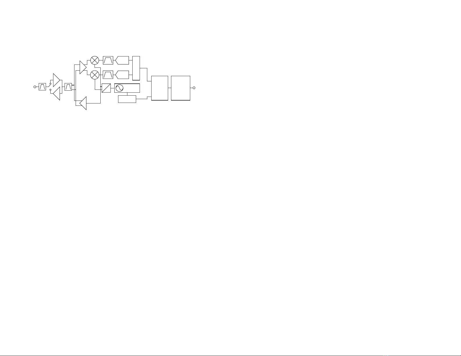
Linx HUM-A-900-PRO-UFL Instruction Manual

HumPRO-ATM Series 900MHz
RF Transceiver Module
Data Guide

Table of Contents
1 Description
1 Features
2 Ordering Information
2 Absolute Maximum Ratings
3 Electrical Specications
5 Typical Performance Graphs
10 Pin Assignments
10 Pin Descriptions
12 Module Pin Assignments
13 Module Dimensions
14 Theory of Operation
15 Module Description
16 Overview
18 Addressing Modes
20 Automatic Addressing
20 Address Register Use
21 Acknowledgements and Assured Delivery
22 Frequency Hopping Spread Spectrum
23 Compatibility with the 250 Series
23 Networking
24 Transmitting Packets
25 Receiving Packets
29 Using the Buffer Empty (BE) Line
30 Exception Engine
32 Carrier Sense Multiple Access (CSMA)
33 Using the Command Response (CRESP) Line
34 Using the CMD Line
35 AES Encryption
38 Using the MODE_IND Line
39 Using the PB Line
Warning: Some customers may want Linx radio frequency (“RF”)
products to control machinery or devices remotely, including machinery
or devices that can cause death, bodily injuries, and/or property
damage if improperly or inadvertently triggered, particularly in industrial
settings or other applications implicating life-safety concerns (“Life and
Property Safety Situations”).
NO OEM LINX REMOTE CONTROL OR FUNCTION MODULE
SHOULD EVER BE USED IN LIFE AND PROPERTY SAFETY
SITUATIONS. No OEM Linx Remote Control or Function Module
should be modified for Life and Property Safety Situations. Such
modification cannot provide sufficient safety and will void the product’s
regulatory certification and warranty.
Customers may use our (non-Function) Modules, Antenna and
Connectors as part of other systems in Life Safety Situations, but
only with necessary and industry appropriate redundancies and
in compliance with applicable safety standards, including without
limitation, ANSI and NFPA standards. It is solely the responsibility of any
Linx customer who uses one or more of these products to incorporate
appropriate redundancies and safety standards for the Life and
Property Safety Situation application.
Do not use this or any Linx product to trigger an action directly
from the data line or RSSI lines without a protocol or encoder/
decoder to validate the data. Without validation, any signal from
another unrelated transmitter in the environment received by the module
could inadvertently trigger the action.
All RF products are susceptible to RF interference that can prevent
communication. RF products without frequency agility or hopping
implemented are more subject to interference. This module does have
a frequency hopping protocol built in, but the developer should still be
aware of the risk of interference.
Do not use any Linx product over the limits in this data guide.
Excessive voltage or extended operation at the maximum voltage could
cause product failure. Exceeding the reflow temperature profile could
cause product failure which is not immediately evident.
Do not make any physical or electrical modifications to any Linx
product. This will void the warranty and regulatory and UL certifications
and may cause product failure which is not immediately evident.
!

– –
1
Description
The HumPROTM Series is a frequency hopping
spread spectrum (FHSS) transceiver designed
for the reliable transfer of digital data. It has a
very fast lock time so that it can quickly wake
up, send data and go back to sleep, saving
power in battery-powered applications. The
module is available in the 915MHz frequency
band. A high-power 25dBm amplifier gives the
HumPRO-A exceptional range.
The module has several features that increase the data transfer reliability. It
ensures that no other modules are transmitting before it begins transmitting
data. Automatic acknowledgements ensure that the remote side received
valid data. Multiple hopping patterns enable several systems to operate
in proximity without interference. A standard UART interface is used for
module configuration and data transfer. A few simple serial commands are
all that are needed for configuration.
All modules have a unique 32-bit serial number that can be used as an
address. Source and destination addressing support point-to-point and
broadcast links. Address masking by the receiving module allows for
creating subnets. Other network topologies can also be implemented.
Housed in a tiny compact reflow-compatible SMD package, the transceiver
requires no external RF components except an antenna, which greatly
simplifies integration and lowers assembly costs. The module has obtained
FCC and Industry Canada modular certifications.
Features
• FHSS Algorithm
• Fast Lock (<30ms at 115kbps)
• Low power modes
• FCC and IC Pre-certified
• Simple UART interface
• No external RF parts required
• Tiny PLCC-44 footprint
• +25dBm TX, -108dBm RX
HumPRO-ATM Series 900MHz
RF Transceiver Module
Data Guide
Figure 1: Package Dimensions
Revised 2/22/2017
0.66 in
(16.66 mm)
1.01 in
(25.70 mm)
0.11 in
(2.90 mm)
40 Restore Factory Defaults
40 Using the Low Power Features
41 Baud Rate and Transmitter Output Power
42 The Command Data Interface
43 Reading from Registers
44 Writing to Registers
45 Command Length Optimization
46 Example Code for Encoding Read/Write Commands
48 The Command Data Interface Command Set
95 Typical Applications
96 Usage Guidelines for FCC Compliance
96 Additional Testing Requirements
97 Information to the user
98 Product Labeling
98 FCC RF Exposure Statement
98 Antenna Selection
100 Power Supply Requirements
100 Antenna Considerations
101 Interference Considerations
102 Pad Layout
102 Castellation Version Reference Design
103 Microstrip Details
104 Board Layout Guidelines
105 Helpful Application Notes from Linx
106 Production Guidelines
106 Hand Assembly
106 Automated Assembly
108 General Antenna Rules
110 Common Antenna Styles
112 Regulatory Considerations
114 Notes

– – – –
2 3
HumPRO-ATM Series Transceiver Specifications
Parameter Symbol Min. Typ. Max. Units Notes
Power Supply
Operating Voltage VCC 2.7 3.3 3.6 VDC
TX Supply Current lCCTX
at +25dBm 383.1 mA
at +24dBm mA 1,2
at +?dBm mA 1,2
RX Supply Current lCCRX 39.2 mA 1,2,3
Power-Down Current lPDN 0.8 µA 1,2
RF Section
Operating Frequency Band FCMHz
HUM-900-PRO-vvv 902 928 MHz
Number of hop channels
@ 19.2kbps RF Rate 50/64
@ 152.34kbps RF Rate 26/32
Channel spacing
@ 19.2kbps RF Rate 375.9 kHz
@ 152.34kbps RF Rate 751.81 kHz
20 dB OBW
@ 19.2kbps RF Rate 64 kHz
@ 152.34kbps RF Rate 315 kHz
Receiver BW
@ 19.2kbps RF Rate 102 kHz
@ 152.34kbps RF Rate 232 kHz
FSK deviation
@ 19.2kbps RF Rate ± 19.2 kHz
@ 152.34kbps RF Rate ± 51 kHz
Scan time / channel (avg)
@ 19.2kbps RF Rate 1.2 ms
@ 152.34kbps RF Rate 0.335 ms
FHSS Lock time
@ 19.2kbps RF Rate 63 ms
@ 152.34kbps RF Rate 26 ms
Modulation 2FSK
Data Encoding 6/7 RLL
Electrical SpecicationsOrdering Information
Figure 2: Ordering Information
Warning: This product incorporates numerous static-sensitive
components. Always wear an ESD wrist strap and observe proper ESD
handling procedures when working with this device. Failure to observe
this precaution may result in module damage or failure.
Absolute Maximum Ratings
Supply Voltage Vcc −0.3 to +3.9 VDC
Any Input or Output Pin −0.3 to VCC + 0.3 VDC
RF Input 0 dBm
Operating Temperature −40 to +85 ºC
Storage Temperature −40 to +85 ºC
Exceeding any of the limits of this section may lead to permanent damage to the device.
Furthermore, extended operation at these maximum ratings may reduce the life of this
device.
Absolute Maximum Ratings
Figure 3: Absolute Maximum Ratings
Ordering Information
Part Number Description
HUM-A-900-PRO-CAS HumPRO-ATM Series High Power Data Transceiver with
Castellation Connection
HUM-A-900-PRO-UFL HumPRO-ATM Series High Power Data Transceiver with u.FL
Connector
EVM-A-900-PRO-CAS HumPRO-ATM Series Carrier Board, Castellation Connection
with an edge-mount RP-SMA connector
EVM-A-900-PRO-UFL HumPRO-ATM Series Carrier Board, UFL Connector
MDEV-A-900-PRO HumPRO-ATM Series Master Development System

– – – –
4 5
HumPRO-ATM Series Transceiver Specifications
Parameter Symbol Min. Typ. Max. Units Notes
Output
Logic Low, MODE_IND,
BE VOLM 0.3*VCC VDC 1,9
Logic High, MODE_IND,
BE VOHM 0.7*VCC VDC 1,9
Logic Low VOL 0.3*VCC 1,10
Logic High VOH 0.7*VCC 1,10
CRESP Hold Time 10 Bits 11
Flash (Non-Volatile) Memory Specifications
Flash Write Cycles 22,000 cycles 12
HumPRO-ATM Series Transceiver Specifications
Parameter Symbol Min. Typ. Max. Units Notes
Number of Hop Sequences 6
Receiver Section
Spurious Emissions –47 dBm
IF Frequency 304.7 kHz
Receiver Sensitivity 5
@ min rate –108 dBm 5
@ max rate –101 dBm 5
RSSI Dynamic Range 86 dB
CSMA RSSI Threshold –70 dBm
Transmitter Section
Max Output Power PO+25 dBm 6
Harmonic Emissions PHTBD dBc 6
Output Power Range PH–9.2 25 dB 6
Antenna Port
RF Impedance RIN 50 Ω4
Environmental
Operating Temp. Range −40 +85 ºC 4
Timing
Module Turn-On Time
Via VCC 63 173 ms 4
Via POWER_DOWN 4 ms 4
Via Standby 4 ms 4
Serial Command Response
Volatile R/W 0.4 5 ms 8
NV Update 2.4 31.5 ms 8
Factory Reset 204 329 ms 14
Channel Dwell Time 400 ms
CMD low to trigger TX with
option TXnCMD tTXnCMD 2 ms 13
Interface Section
UART Data rate 9,600 115,200 bps
Input
Logic Low VIL 0.3*VCC VDC
Logic High VIH 0.7*VCC VDC
1. Measured at 3.3V VCC
2. Measured at 25ºC
3. Input power < -60dBm
4. Characterized but not tested
5. PER = 5%
6. Into a 50-ohm load
7. No RF interference
8. From end of command to start of
response
9. 60mA source/sink
10. 6mA source/sink
11. End of CMD_DATA_OUT stop bit to
change in CRESP
12. Number of register write operations
13. With CSMA disabled
14. Start of factory reset command to end
of last ACK response
Figure 4: Electrical Specifications
Typical Performance Graphs
Figure 5: HumPRO-ATM Series Transceiver Max Output Power vs. Supply Voltage
20.0
21.0
22.0
23.0
24.0
25.0
26.0
27.0
28.0
2.73.0 3.
33
.6
TX Output Power (dBm)
Supply Voltage (V)
-40°C
25°C
85°C

– – – –
6 7
0.00
50.00
100.00
150.00
200.00
250.00
300.00
350.00
400.00
-15.00 -10.00 -5.000.005.00 10.00 15.0020.00 25.00 30.00
Supply Current (mA)
TX Output Power (dBm)
-40°C
25°C
85°C
Figure 6: HumPRO-ATM Series Transceiver Average Current vs. Transmitter Output Power at 2.5V
0.00
50.00
100.00
150.00
200.00
250.00
300.00
350.00
400.00
450.00
500.00
-15.00 -10.00 -5.00 0.00 5.0010.00 15.0020.00 25.0030.00
Supply Current (mA)
TX Output Power (dBm)
-40°C
25°C
85°C
Figure 7: HumPRO-ATM Series Transceiver Average TX Current vs. Transmitter Output Power at 3.3V
220.0
270.0
320.0
370.0
420.0
470.0
520.0
2.7 3.0 3.
33
.6
Supply Current (mA)
Supply Voltage (V)
-40°C
25°C
85°C
Figure 9: HumPRO-ATM Series Transceiver TX Current vs. Supply Voltage at Max Power
200.0
250.0
300.0
350.0
400.0
450.0
2.7 3.0 3.
33.6
Supply Current (mA)
Supply Voltage (V)
-40°C
25°C
85°C
Figure 8: HumPRO-ATM Series Transceiver TX Current vs. Supply Voltage at 24dBm

– – – –
8 9
120.0
140.0
160.0
180.0
200.0
220.0
240.0
2.7 3.0 3.
33.6
Supply Current (mA)
Supply Voltage (V)
-40°C
25°C
85°C
Figure 10: HumPRO-ATM Series Transceiver TX Current vs. Supply Voltage at 20dBm
0.00
0.50
1.00
1.50
2.00
2.50
2.73.0 3.
33
.6
Supply Current (µA)
SupplyVoltage (V)
-40°C
25°C
85°C
Figure 12: HumPRO-ATM Series Transceiver Standby Current Consumption vs. Supply Voltage
-100
-90
-80
-70
-60
-50
-40
-30
-20
-10
0
-110 -90 -70 -50-30 -10
RSSI Reading (dBm)
Input Power (dBm)
-40°C
25°C
85°C
Figure 13: HumPRO-ATM Series Transceiver RSSI Reading vs. Input Power
32.00
34.00
36.00
38.00
40.00
42.00
44.00
2.7 3.0 3.
33.6
Supply Current (mA)
Supply Voltage (V)
-40°C
25°C
85°C
Figure 11: HumPRO-ATM Series Transceiver RX Scan Current vs. Supply Voltage, 115.2kbps
Current consumption while the module is scanning for a transmission. The current is
approximately 0.3mA higher when receiving data at 115.2kbps.

– – – –
10 11
Pin Assignments
5
6
7
1
2
3
4
44
NC
NC
NC
BE
NC
NC
NC
9
10
11
8
NC
NC
NC
GND
12 13 14 15 16 17 18 19 20
CRESP
EX
PB
CMD_DATA_OUT
NC
NC
CMD_DATA_IN
NC
NC
21 22
VCC
NC
43 42 41 40 39 38 37 36 35 34
POWER_DOWN
NC
NC
NC
NC
NC
RESET
MODE_IND
NC
CTS
CMD
ANT
GND
33 32
ANT
Figure 14: HumPRO-ATM Series Transceiver Pin Assignments (Top View)
Pin Descriptions
Pin Number Name I/O Description
1, 2, 3, 5, 6,
7, 8, 10, 11,
17-21, 37, 38,
39, 41, 42, 44
NC — No Electrical Connection. Do not connect
any traces to these lines.
4 BE O
Buffer Empty. This line is high when the
UART input buffer is empty, indicating
that all data has been transmitted. If
acknowledgment is active, it also indicates
that the receiving module has acknowledged
the data or a retry exception has occurred.
9, 32 GND — Ground
12 EX O
Exception Output. A mask can be set
to take this line high when an exception
occurs.
Pin Descriptions
Pin Number Name I/O Description
13 CRESP O
Command Response. This line is low when
the data on the CMD_DATA_OUT line is
a response to a command and not data
received over the air.
14 PB I
Push Button input. This line can be
connected to Vcc through a normally open
push button. Button sequences can reset
configurations to default and join modules
into a network. Pull low when not in use;
do not leave floating.
15 CMD_DATA_OUT O Command Data Out. Output line for data
and serial commands
16 CMD_DATA_IN I Command Data In. Input line for data (CMD
is high) and serial commands (CMD is low).
22 VCC — Supply Voltage
33 ANTENNA — 50-ohm RF Antenna Port
34 CTS O
UART Clear To Send, active low. This line
indicates to the host microcontroller when
the module is ready to accept data. When
CTS is high, the module is busy. When CTS
is low, the module is ready for data.
35 CMD I
Command Input. When this line is low,
incoming bytes are command data.
When high, incoming bytes are data to be
transmitted.
36 MODE_IND O
Mode Indicator. This line indicates module
activity. It can source enough current to drive
a small LED, causing it to flash. The duration
of the flashes indicates the module’s current
state.
40 RESET I
This line resets the module when pulled low.
It should be high for normal operation. This
line has an internal 10k resistor to supply, so
leave it unconnected if not used.
43 POWER_DOWN I
Power Down. Pulling this line low places the
module into a low-power state. The module
is not functional in this state. Pull high for
normal operation. Do not leave floating.
Figure 15: HumPRO-ATM Series Transceiver Pin Descriptions
Pin Descriptions

– – – –
12 13
0.66 in
(16.66 mm)
1.01 in
(25.70 mm)
0.11 in
(2.90 mm)
Module Dimensions
Figure 18: HumPRO-ATM Series Transceiver Pre-certified Version Dimensions
Module Pin Assignments
The module has two versions that differ in the antenna connection. The
antenna connection is routed to either a castellation (-CAS) or a u.FL
connector (-UFL), depending on the part number ordered.
5
6
7
1
2
3
4
44
NC
NC
NC
BE
NC
NC
NC
9
10
11
8
NC
NC
NC
GND
12 13 14 15 16 17 18 19 20
CRESP
EX
PB
CMD_DATA_OUT
NC
NC
CMD_DATA_I
N
NC
NC
21 22
VCC
NC
43 42 41 40 39 38 37 36 35 34
POWER_DOWN
NC
NC
NC
NC
NC
RESET
MODE_IND
NC
CTS
CMD
ANT
GND
33 32
NC
Figure 16: HumPRO-ATM Series Transceiver Pre-certified Version Pin Assignments - Castellation Connection
(Top View)
5
6
7
1
2
3
4
44
NC
NC
NC
BE
NC
NC
NC
9
10
11
8
NC
NC
NC
GND
12 13 14 15 16 17 18 19 20
CRESP
EX
PB
CMD_DATA_OUT
NC
NC
CMD_DATA_I
N
NC
NC
21 22
VCC
NC
43 42 41 40 39 38 37 36 35 34
POWER_DOWN
NC
NC
NC
NC
NC
RESET
MODE_IND
NC
CTS
CMD
NC
GND
33 32
ANT
Figure 17: HumPRO-ATM Series Transceiver Pre-certified Version Pin Assignments - UFL Connection (Top View)

– – – –
14 15
Theory of Operation
The HumPROTM Series transceiver is a low-cost, high-performance
synthesized FSK / GFSK / MSK transceiver. Figure 19 shows the module’s
block diagram.
The HumPROTM Series transceiver operates in the 902 to 928MHz
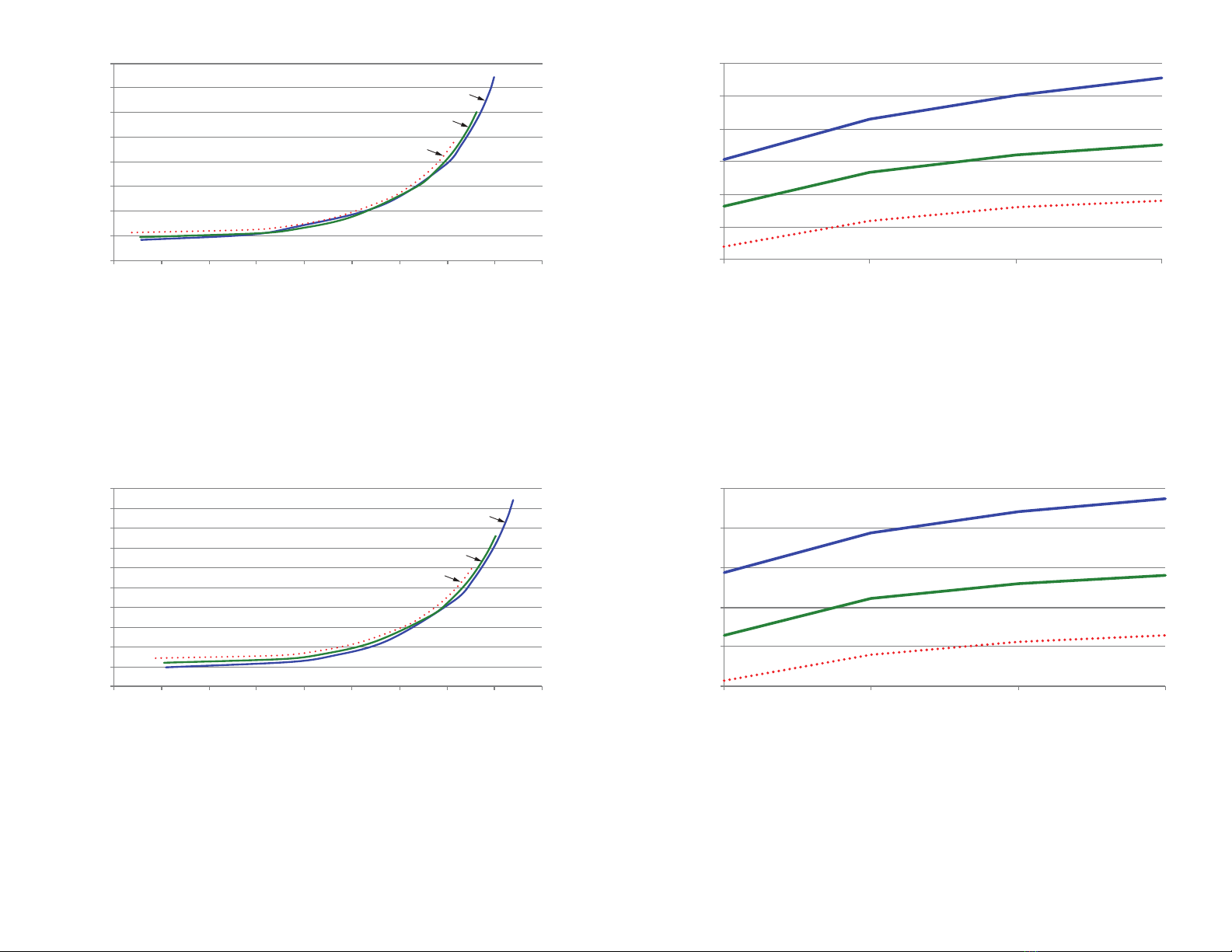
frequency band. The transmitter output power is programmable. The
range varies depending on the antenna implementation and the local RF
environment.
The RF carrier is generated directly by a frequency synthesizer that includes
an on-chip VCO. The received RF signal is amplified by a low noise
amplifier (LNA) and down-converted to I/Q quadrature signals. The I/Q
signals are digitized by ADCs.
An additional front-end power amplifier boosts the transmitter power to
0.5W (~27dBm). An additional LNA improves the receiver sensitivity by
around 6dB.
A low-power onboard communications processor performs the radio
control and management functions including Automatic Gain Control
(AGC), filtering, demodulation and packet synchronization. A control
processor performs the higher level functions and controls the serial and
hardware interfaces.
A crystal oscillator generates the reference frequency for the synthesizer
and clocks for the ADCs and the processor.
PA
LNA
0
90
FREQ
SYNTH
ADC
ADC
DEMODULATOR
MODULATOR
ANTENNA PROCESSORGPIO /
INTERFACE
INTERFACE
PA
LNA
Figure 19: HumPRO-ATM Series Transceiver RF Section Block Diagram
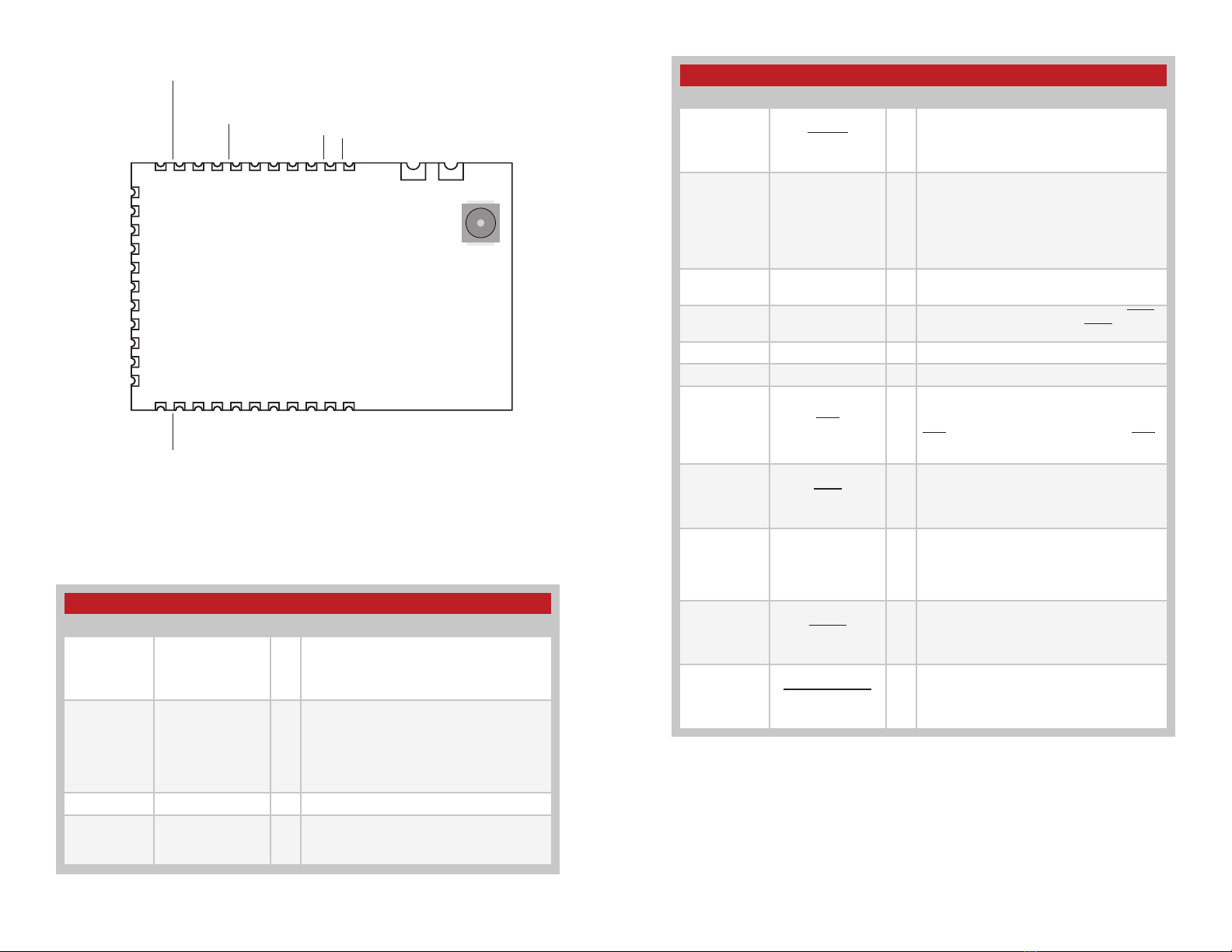
Module Description
The HumPROTM Series module is a completely integrated RF transceiver
and processor designed to transmit digital data across a wireless link.
It employs a fast-locking FHSS system for noise immunity and higher
transmitter output power as allowed by government regulations.
When the module does not have data to send it scans all of the channels
for incoming data. If it finds a valid preamble, it pauses and looks for
the start of a packet. When it receives a valid packet with a matching
destination address the module outputs the data through the UART.
The transmitting module accepts data bytes through its UART until a
configurable number of bytes is reached or a configurable timeout expires
between bytes on the UART. At this point the module transmits the packet.
When the module has data to send it goes to the next channel in its
hopping pattern. It measures the RSSI on that channel to ensure that the
channel is clear. If the RSSI check passes, then it transmits the packets. If
the RSSI fails, then it implements a random wait time and tries again. When
the channel is clear, the module transmits the data.
The module can stay on one channel for up to 400ms. If the module is
ready to start transmitting near the end of the channel time, it transmits the
number of bytes that it can in the remaining time. It then hops to the next
channel in its hopping pattern to transmit the remaining data.
The module supports automatic acknowledgements for assured delivery.
When enabled, the receiving module responds to a valid transmission with
an acknowledgement to let the transmitting module know that it received
the data. If an acknowledgement is not received then the transmitting
module repeats the transmission for a configurable number of retries. If the
retry limit is exceeded without an acknowledgement then the transmitting
module issues an exception error to let the host micro know of the
communication problem.
A standard UART interface is used to configure the module for operation
and for the data input and output. This is suitable for direct connection to
UARTs on many microcontrollers, USB converters and RS-232 converters.
A simple command set is used for configuration and control.
Modules can be pre-configured for fixed point-to-point or broadcast
topologies allowing streaming data (no commands) during operation.

– – – –
16 17
Overview
The HumPROTM Series RF transceiver module offers a number of features
that make it suitable for many data transfer applications. This section
provides a basic overview of the features while following sections dive into
them in more detail.
Addressing
The modules have a very powerful addressing method. Each module is
given a unique 16 or 32 bit address. The receiving modules use an address
mask that determines how it responds to a received transmission.
The addressing and masking allow for the creation of point-to-point,
many-to-one and one-to-many wireless links. This allows the creation of
many network topologies, such as star, tree and mesh. The routing for the
network topology is managed outside the module.
The addressing is the primary configuration when getting started with the
modules. RG-00105, the HumPROTM Addressing Mode Reference Guide
has details about configuring the addressing.
Acknowledgements and Assured Delivery
The modules support assured delivery in the form of acknowledgements
and retries. When the acknowledgements are enabled, the receiving
device sends an acknowledge message to let the sender know that the
transmission was received. If the sender does not get an acknowledgement
it resends the message up to a configurable number of retries. If there is
still no acknowledgement, the module triggers an exception to let the host
processor know of the error.
Command Mode and Data Mode
The module has two main interface modes controlled by the state of the
CMD line. Command mode routes the data coming in on the CMD_DATA_
IN line to the processor for configuring the module. Data mode routes
the data to the transmitter for transmission over-the-air. The CMD line is
normally controlled by an external microcontroller.
Encryption
The module supports AES-128 encryption to provide a secure wireless link.
All of the modules must have encryption enabled and be using the same
key in order for communication to be successful. There are two ways of
entering an encryption key: directly by writing the key to registers through
the Command Data Interface or through a JOIN process.
Streaming Data and Explicit Packets
The module’s default configuration is for streaming data. At some UART
rates the module sends the data at a higher rate over-the-air than it is input
on the UART. This hides the time required for the protocol transactions
and the frequency hopping. The result is that the data appears to stream
through the module with no breaks in the data apparent to the host
processor.
Alternatively, the module can be configured for explicit packet transmission.
This allows the host processor to control when packets are sent and what
data is in each packet
Exceptions and Host Processor Interface
The module has several indicator lines that provide feedback to the host
processor on the module’s operation and current status. This includes an
exception line (EX) that informs the processor when errors occur so that it
can take steps to manage the issue gracefully. The state of the status lines
can also be read through the module’s Command Data Interface to reduce
the number of hardware connections that are required.
Command Data Interface
The module has a Command Data Interface that consists of a set of serial
commands entered through a UART. These are shorter and simpler than AT
commands that are popular with many modules. These commands control
the configuration of the module as well as allow feedback on the operation
and status of the module.
Carrier Sense Multiple Access (CSMA)
The module implements a Carrier Sense Multiple Access method. It listens
to the channel and makes sure that it is clear before it transmits. If the
channel is in use, the module either waits for it to clear or hops to the next
channel depending on its current state. This reduces the overall potential
for interference and improves the robustness of the link.
High Power Front End Amplifiers
The HumPRO-A adds a high-power 25dBm power amplifier and an
additional low noise amplifier to greatly increase the module’s link budget.
With +25dBm transmit power and -108dBm sensitivity, the resulting link
budget of 133dBm gives the module a line-of-sight range of over 7 miles
with good antennas and a good operational environment.

– – – –
18 19
Addressing Modes
The module has very flexible addressing methods selected with the
ADDMODE register. It can be changed during operation. The transmitting
module addresses packets according to the addressing mode
configuration. The receiving module processes all addressing types
regardless of the ADDMODE configuration. If the received message
matches the addressing criteria, it is output on the UART. Otherwise it is
discarded. The ADDMODE configuration also enables assured delivery.
There are three addressing modes: DSN, User and Extended User. Each
mode offers different communications methods, but all use source and
destination addressing. The source address is for the transmitting unit,
the destination address is the intended receiver. Each mode uses different
registers for the source and destination addresses.
All three addressing modes can be configured to be compatible with the
older 250 Series modules. The default operation has an additional level
of masking on the receiving module that helps prevent interference from
adjacent networks.
The following sections give brief descriptions of the three modes, but a
detailed explanation and examples are given in RG-00105, the HumPROTM
Addressing Mode Reference Guide.
DSN Addressing Mode
Device Serial Number Addressing mode is the simplest mode and
supports point-to-point communications. Each module is programmed at
the factory with a unique 4-byte serial number that cannot be changed.
These bytes are found in the non-volatile read-only MYDSN registers
(MYDSN[3-0]). DSN Addressing mode uses this serial number as an
address. The transmitting unit’s DSN is used as the source address and
the intended receiver’s DSN is written into the destination address registers
(DESTDSN[3-0]). All modules within range hear the transmission, but only
the module with the serial number that matches the destination address
outputs the data on its UART. All others ignore the transmission.
User Addressing Mode
User Addressing Mode is a more flexible method than DSN Addressing
Mode. It uses the customer ID bytes (CUSTID[1-0]) for unencrypted
messages and two of the user destination bytes (UDESTID[1-0]) as a
destination address. The customer ID bytes are programmed at the factory
and cannot be changed. These are determined by the factory for specific
customers to prevent their systems from operating with any other systems.
Contact Linx for more details.
The module’s local address is contained in two of the user source ID
registers (USRCID[1-0]). In this mode, USRCID [1-0] contain the node
address and USRCID [3-2] must be 0 in the receiver.
In normal operation each module has a user ID mask (UMASK[3-0]) that
splits the 32 address bits into up to three fields to provide a network
address and address fields for sub-networks, supporting both individual
addressing and broadcast addressing within the user’s network. A detailed
explanation and examples are given in Reference Guide RG-00105. The
16 bits in the UDESTID[1-0] registers are transmitted. The upper 16 bits of
USRCID[3-2] in the receiver must be 0.
If acknowledgements are enabled, only the module with a user source ID
that exactly matches the transmitted user destination ID responds. The
mask is not used for this determination.
Extended User Addressing Mode
Extended User Addressing mode is the same as User Addressing mode
but uses 32-bit addresses. The two customer ID bytes are still used
(CUSTID[1-0]) for unencrypted messages but four bytes are used for the
user destination address (UDESTID[3-0]), user source ID (USRCID[3-0]) and
user ID mask (UMASK[3-0]). This provides more addressing capabilities at
the expense of more overhead in the packet.
Network Addressing
Network Addressing is selected by setting COMPAT to 0x03. It allows
the receiver to receive all messages sent in User Address or Extended
User Address mode with a destination address matching the USRCID
group 1 bits (continuous high-order zero bits in UMASK). For example,
with USRCID = 0x12345678 and UMASK = 0x000FFFFF, messages with
destination address 0x123zzzzz, where z is any value, is received.

– – – –
20 21
Acknowledgements and Assured Delivery
When a module transmits with assured delivery enabled, the receiving
module returns an acknowledgement packet. The transmitting module
waits for this acknowledgement for a preset amount of time based on the
data rate. If an acknowledgement is not received, it retransmits the packet.
If the receiver receives more than one of the same packet, it discards
the duplicate packet contents but sends an acknowledgment. This way,
duplicate data is not output by the module.
If the received destination address matches the local address, the
receiving module immediately sends an acknowledgement. This packet
lets the sending module know that the message has been received.
An acknowledgement packet is sent immediately following reception;
CSMA delay is not applied to these packets since permission belongs
to the interacting modules. When the sending module receives the
acknowledgement packet, it marks the current block of data as completed.
If this is the last message in the queue, the sending module takes the BE
line high to indicate that all outgoing data has been sent.
Assured delivery should only be used when addressing a specific module
in a point-to-point link. It should not be used when multiple receivers are
enabled. When address masking is used, only the receiver with an exact
match to the address in the transmitted packet responds. If none of the
enabled receivers has an exact match, then there is no response and the
transmitting module continues to re-transmit the data until the max number
of retries is attempted. This causes the transmitting module to appear slow
or unresponsive. It also impedes valid communications.
Automatic Addressing
The module supports an automatic addressing mode that reads the Source
Address from a valid received packet and uses it to fill the Destination
Address register. This makes sure that a response is sent to the device that
transmitted the original message. This also allows the host microcontroller
to read out the address of the sending unit. The automatic addressing is
enabled for the different addressing modes with register AUTOADDR.
Address Register Use
Figure 20 shows the address registers that are used with each addressing
mode.
Figure 20: HumPRO-ATM Series Transceiver Address Register Use
HumPRO-ATM Series Transceiver Address Registers
COMPAT 0x00 (Relaxed Addressing) 0x02 (Normal Addressing)
ADDMODE
0x04
(DSN)
0x06
(User)
0x07
(Ex User)
0x04
(DSN)
0x06
(User)
0x07
(Ex User)
0x14
(DSN
+ACK)
0x16
(User
+ACK)
0x17
(ExUser
+ACK)
0x14
(DSN
+ACK)
0x16
(User
+ACK)
0x17
(ExUser
+ACK)
UDESTID[3-0] X X
UDESTID[1-0] X X
USRC[3-0] X X X
USRC[1-0] X
UMASK[3-0] X X X
UMASK[1-0] X
DESTDSN[3-0] X X

– – – –
22 23
Frequency Hopping Spread Spectrum
The module uses Frequency Hopping Spread Spectrum to allow operation
at higher power levels per regulations and to reduce interference with other
transmitters. The module is configured for operation in one of 6 different
hopping sequences. Each sequence uses 26 channels for the high RF data
rate or 50 channels for the low RF data rate. Modules must use the same
hopping sequence to communicate. Assigning different hopping sequences
to multiple networks in the same area minimizes the interference.
When the module is awake and not transmitting, it rapidly scans all
channels for a packet preamble. When a module starts transmitting at the
beginning of a new channel, it transmits a packet with a long preamble of
alternating 0 and 1 bits. This long preamble is sufficient to allow receiving
modules to scan through all of the channels in the hopping sequence and
find it. Modules that are scanning detect the preamble and pause on that
channel, waiting for a valid packet.
If a packet is received with a valid CRC (unencrypted) or authentication
(encrypted), the header is examined to determine whether the module
should synchronize to the transmitter. Synchronization requires that the hop
sequence matches and that the message is addressed to the receiver.
When synchronized, the receiver stays on the current channel to either
transmit a packet or to receive an additional packet. Additional packets
transmitted on the same channel within the time slot use short preambles
since the receivers are already listening to the current channel.
At the end of the time slot for the current channel, all modules which locked
to the original transmission switch to the next channel in the hop sequence.
The first transmission on each new channel has a long preamble.
A receiver that has synchronized to a transmitter continues to stay in
synchronism by staying on the received channel until the expiration of the
time slot, then waiting on the next hop channel for the duration of the time
slot. If no further packets are received, the receiver loses lock and reverts
to scanning. This allows the receiver to stay synchronized for a short while
if a packet is not received correctly.
The module supports the option to send the long preamble with every
packet rather than just the first packet on each channel. This can be
beneficial for systems that have modules asleep most of the time. It gives
modules that just woke up the chance to synchronize to any transmitted
packet instead of having to wait for the transmitter to complete its time slot
and jump to the next channel. This can reduce the synchronization time
and power consumption of the sleeping nodes.
Compatibility with the 250 Series
When DSN mode is used with a specific address, the module can
communicate with 250 Series modules at UART data rates of 38,400 to
115,200 bps, non-encrypted. For other addressing modes, the HumPROTM
Series modules can be configured to operate with them. Setting the
COMPAT register to 0x00 enables the compatible operation. This allows
mixed-mode systems and upgrades of legacy products that still maintain
backwards compatibility. Only the higher baud rates are compatible.
The main feature of compatibility operation is that it configures the same
addressing methods used by the 250 Series. These methods are more
susceptible to interference from adjacent networks of 250 Series modules
which use DSN (GUI) broadcast messages. Please see Reference Guide
RG-00105 for more details.
Networking
The HumPROTM Series modules can be used to create many types of
wireless networks. The modules do not provide network routing since the
internal memory size of the module would limit the overall network size. The
HumPROTM can work as the MAC/PHY layers of a network stack and the
memory and processing speed of the external microcontroller can be sized
according to the size of the network that is needed for the application.
This requires more software development, but avoids the cost of adding
extra memory on the module for applications that don’t need it. Linx can
assist with network frameworks and concepts and can create custom
designs on a contract basis. Contact Linx for more details.

– – – –
24 25
Transmitting Packets
In default operation when transmitting, the host microcontroller writes bytes
to the CMD_DATA_IN line while the CMD line is held high at the baud rate
selected by the UARTBAUD register. The incoming bytes are buffered until
one of the following conditions triggers the packet to be transmitted:
1. The number of bytes in the buffer exceeds the value in the Byte Count
Trigger (BCTRIG) register.
2. The time since the last received byte exceeds the value in the Data
Timeout (DATATO) register.
3. A SENDP command is written to the CMD register.
4. The CMD line is taken low with option PKOPT: TXnCMD = 1.
5. The number of buffered bytes exceeds what can be sent before the
radio must hop channels.
The first four conditions can be controlled by the host microcontroller. In
the last case, the module transmits what it can in the remaining time then
sends the rest on the next channel. This can cause the data to be divided
up into multiple packets and is not within the control of the host micro.
In cases where all data needs to be sent in the same packet or where the
microcontroller needs greater control over the radio, the HumPROTM offers
explicit control of packet transmission with options in the PKTOPT register.
When the TXPKT option is enabled (PKTOPT register, bit 0 = 1), the data is
held until a SENDP command is written to the CMD register. Alternatively,
if option TXnCMD is enabled (PKTOPT register, bit 1 = 1), then lowering
the CMD line triggers the packet transmission, reducing the number of
UART transactions that are required. The BCTRIG, DATATO and hop-timing
conditions are ignored when the TXPKT option is enabled.
Once triggered, the transmitted packet contains the bytes in the buffer as
of the trigger event, even if more data bytes are received before the packet
can be sent. Multiple outgoing packets can be buffered in this way.
If the full packet cannot be sent in the time remaining on the current
channel, then it is held until the module hops to the next channel.
This option gives the host microcontroller very fine control over when
packets are transmitted and what they contain.
Receiving Packets
In default operation when receiving valid packets, the module outputs all
received bytes as soon as the packet is validated (CRC checks pass if
unencrypted or key-based verification if encrypted) and if the addressing
permits it at the baud rate selected by the UARTBAUD register. No
command or control bytes are output and no action is required of an
external microcontroller. The first byte from a packet directly follows the last
byte of the previously received packet.
In cases where the host microcontroller needs more control over the data
or where dynamic configuration changes could set up race conditions
between incoming data and outgoing commands, the module offers
explicit control over received packets.
When the RXPKT option is enabled (PKTOPT register, bit 2 = 1), received
data is output on the CMD_DATA_OUT line one packet at a time after a
GETPH, GETPD, or GETPHD command is written to the CMD register.
Writing one of these commands begins the received packet transfer cycle.
Two lines are used as flow control and indicators during the transfer cycle.
The CMD line is controlled by the host microcontroller. The module uses
either the CTS line or the CRESP line as a status line, depending on the
state of the RXP_CTS option in the PKOPT register.
When a valid packet is received, the EX_RXWAIT exception flag is set in
the EEXFLAG1 register. If the corresponding bit in the EEXMASK1 register
is set, then the EX line goes high. The host microcontroller can monitor
the EX line or periodically check the EEXFLAG or LSTATUS registers to
determine if data is ready to be read.
The transfer cycle is begun by writing a Get Packet Header (GETPH),
Get Packet Data (GETPD), or Get Packet Header and Data (GETPHD)
command to the CMD register. The module sends the command ACK byte
and sets the selected status line high. Once the status line goes high, the
host microcontroller sets the CMD line high and the module outputs the
received data. The command sent determines whether the bytes sent are
the header, data, or header followed by data.
When all packet bytes have been sent the control line goes low. When
the host microcontroller detects that the line is low, it sets CMD low,
completing the transfer cycle. The cycle is shown in Figure 21.

– – – –
26 27
The Cust ID field is a number that can be assigned to a specific customer.
Only modules with the same customer ID respond to unencrypted
transmissions. By default, Cust ID is 0x7FFF for packets transmitted with
COMPAT = 2 or 0xFFFF for packets transmitted with COMPAT = 0. This
field is not used in DSN mode.
The Dest Addr field has the received destination address. This is 2 bytes
long with User Addressing Mode and 4 bytes with DSN and Extended User
Addressing Modes.
The Source Addr Field is the address of the transmitting module. This
is 2 bytes long with User Addressing Mode and 4 bytes with DSN and
Extended User Addressing Modes.
The Data Length byte indicates how many bytes of data are in the packet.
This value is the same in the packet header and the associated data block.
If a GETPH was sent and header data received, the following data can
then be read by repeating the cycle with the GETPD command. If the next
GETPx command is a GETPH or GETPHD, the data associated with the
header read by GETPH is discarded and the header or header plus data of
the following packet is returned.
If there is RF-received data waiting to be sent to the UART and the mask
for EX_RXWAIT is set in the EEXMASK register, EX is raised if it is low.
If there is no packet waiting when a GETPx command is sent, the control
line is still taken high and not reset until after CMD goes high, thereby
performing a zero-byte transfer cycle.
The header and payload structures differ between encrypted packets
and unencrypted packets. The header and data structures for explicit
unencrypted packets are shown in Figure 22.
The Tag field identifies the start of the block and if it is the header
information (0x01) or the packet data (0x02).
The Header Length field identifies the number of header bytes that follow.
The Frame Type field identifies what kind of packet was received. The
values are shown in Figure 23.
The Hop ID field is the hop sequence number, 0 - 5.
The Sequence byte is incremented for each new packet, modulo 255. A
received packet is discarded if the sequence byte matches the previously
received packet to prevent delivering duplicate copies of an automatically
retransmitted packet.
CMD
CMD_DATA_IN
CMD_DATA_OUT
CONTROL
EX
Packet In
Exception for unread packet
Read Packet Command
ACK Packet to UART
Any Command
Any Response
Figure 21: HumPRO-ATM Series Transceiver Received Packet Transfer Cycle
Tag
0x01
Frame
Type
1
Header
Length
1
Hop ID
1
Sequence
1
Dest DSN
4
Source
DSN
4
Data
Length
1
DSN Address Packet Header
Packet Data
Tag
0x02
Data
Data Length Bytes
Data
Length
1
Tag
0x01 1
Header
Length
1
Hop ID
1
Sequence
1
Cust ID
2
Dest Addr
2 or 4
Source
Addr
2 or 4
Source
DSN
4
User Address Packet Header
Data
Length
1
Frame
Type
Figure 22: HumPRO-ATM Series Transceiver Unencrypted Packet Header and Data Structure
Figure 23: HumPRO-ATM Series Transceiver Frame Types
HumPRO-ATM Series Transceiver Frame Types
Frame Type Packet Type
0x04 DSN Addressing Mode
0x06 User Addressing Mode
0x07 Extended User Addressing Mode
+0x10 Acknowledgements Enabled
+0x20 Encrypted Packet
+0x40 Long Preamble Packet

– – – –
28 29
The header and data structures for explicit encrypted packets are shown
in Figure 24. The header and data blocks returned by the module are the
decrypted message contents.
The Tag, Header Length and Frame Type fields are the same as for
unencrypted packets.
The Hop Key field uses the first three low-order bits to indicate the Hop
Sequence number, which is the same as unencrypted packets. The upper
two bits indicate which key is being used. Either the factory-set key that is
used to securely transfer the network key or a network key that has been
written or created by the JOIN process. This is shown in Figure 25.
The Sequence bytes contain a counter that is incremented for each new
transmitted message. The initial value is randomized when the module
is reset. The extended sequence becomes part of an initialization vector
which is used to vary the encrypted contents of identical packets. A
received packet is discarded if the sequence byte matches the previously
received packet to prevent delivering duplicate copies of an automatically
retransmitted packet.
Tag
0x11
Frame
Type
1
Header
Length
1
Hop Key
1
Sequence
6
Dest DSN
4
Source
DSN
4
EBlock
Length
1
Encrypted DSN Address Packet Header
Encrypted Packet Data
Tag
0x12
Data
Data Length Bytes
Data
Length
1
Tag
0x11
Frame
Type
1
Header
Length
1
Hop Key
1
Sequence
6
Dest Addr
2 or 4
Source
Addr
2 or 4
Source
DSN
4
Encrypted User Address Packet Header
EBlock
Length
1
Payload
Type
1
Payload
Type
1
Figure 24: HumPRO-ATM Series Transceiver Encrypted Packet Header and Data Structure
HumPRO-ATM Series HopKey Byte Values
HopKey Bit Value
0 - 3 Hop Sequence Number, 1 to 5
4 - 5 = 0
6 - 7
Encryption key
0 = factory
1 = user network
Figure 25: HumPRO-ATM Series HopKey Byte Values
The Dest DSN, Source DSN, Dest Addr and Source Addr fields are the
source and destination addresses, the same as in unencrypted packets.
The EBlock length field is the total number of bytes of data in the encrypted
payload block. This length includes the Payload Type byte.
The Payload Type byte indicates what data is contained in the payload.
0x00 indicates that the payload is user data. 0x01 indicates that the
payload is the 16-byte AES key followed by any user data. This is used for
transferring the network encryption key during the JOIN process.
For the Encrypted Packet Data packet, the Data Length byte indicates the
number of bytes of data payload that follow. This value is one less than the
EBlock length in the header. The reason for this is that the Payload Type
byte is included in the encrypted block, but is reported with the header
since it is not user data.
Using the Buffer Empty (BE) Line
The BE line indicates the state of the module’s UART buffer. It is high to
indicate that the UART input buffer is empty, indicating that all data has
been transmitted. When the module receives data on the CMD_DATA_IN
line and the CMD line is high, the BE line is lowered until all data in the
buffer has been processed by the protocol engine. If acknowledgement
is not enabled, the BE line is raised as soon as the module transmits the
outgoing packets. If acknowledgement is enabled, the buffer is not updated
until either the data transmissions are acknowledged by the remote end or
delivery fails after the maximum number of retries. When the BE line returns
high, the EX line may be sampled, or the EXCEPT or EEXFLAG register
polled to determine if an error occurred during transmission.
The state of the BE line can be read in the LSTATUS register, reducing the
number of hardware connections that are needed.

– – – –
30 31
Exception Engine
The HumPROTM is equipped with an internal exception engine to notify the
host microcontroller of an unexpected event. If errors occur during module
operation, an exception is raised. There are two methods of driving the EX
pin when an exception condition exists:
1. From the EXMASK and EXCEPT registers (legacy operation)
2. From the EEXMASKx and EEXFLAGx registers (standard operation)
If EXMASK is non-zero, the first method is used, otherwise the second
method is used.
For legacy operation with the 250 and 25 Series, the EX line is set and
reset by the Exception (EXCEPT) register processing. It is set when
an exception occurs and the exception code ANDed with the current
Exception Mask (EXMASK) register is non-zero. It is reset when the
EXCEPT register is read through a command. No other operations affect
the state of EX. Setting EXMASK non-zero does not change the state of
EX.
If an exception code is already present in the register when an error occurs,
the new exception code overwrites the old value. Exception codes are
organized by type for ease of masking. Figure 26 lists the exception codes
and their meanings.
HumPRO-ATM Series Transceiver Exception Codes
Exception Code Exception Name Description
0x08 EX_BUFOVFL Incoming UART buffer overflowed.
0x09 EX_RFOVFL Outgoing UART buffer overflowed.
0x13 EX_WRITEREGFAILED Attempted write to register failed.
0x20 EX_NORFACK Acknowledgement packet not received
after maximum number of retries.
0x40 EX_BADCRC Bad CRC detected on incoming packet.
0x42 EX_BADHEADER Bad CRC detected in packet header.
0x43 EX_BADSEQID Sequence ID was incorrect in ACK packet.
0x44 EX_BADFRAMETYPE
Attempted transmit with Invalid setting in
reg:NETMODE or invalid packet type in
received packet header
Figure 26: HumPRO-ATM Series Transceiver Exception Codes
The EX line can be asserted to indicate to the host that an error has
occurred. The EXCEPT register must be read to reset the line. Figure 27
lists some example exception masks.
The exception mask has no effect on the exceptions stored in the
exception register. It only controls which exceptions affect the EX line.
The extended exception registers offer more functionality with more
exceptions and a separate bit for each exception. These registers are the
default and should be used with new applications. When an exception sets
an exception code in the EXCEPT register, the corresponding flag in the
EEXFLAG register is also set.
The EX line is set and reset by the Extended Exception Flags (EEXFLAG)
and Extended Exception Mask (EEXMASK) register processing. It is set
whenever the EEXFLAG value ANDed with the EEXMASK value is non-zero.
EX can change on any write to either of these registers that affects the
result of ANDing the registers. Clearing an EEXFLAG register bit or value
can leave EX set if there is another masked condition bit set.
The state of the EX line can also be read in the LSTATUS register, reducing
the number of hardware lines that are required.
HumPRO-ATM Series Transceiver Example Exception Masks
Exception Mask Exception Name
0x08 Allows only EX_BUFOVFL and EX_RFOVFL to trigger the EX line
0x10 Allows only EX_WRITEREGFAILED to trigger the EX line
0x20 Allows only EX_NORFACK to trigger the EX line
0x40 Allows only EX_BADCRC, EX_BADHEADER, EX_BADSEQID and
EX_BADFRAMETYPE exceptions to trigger the EX line
0x60
Allows EX_BADCRC, EX_BADHEADER, EX_BADSEQID, EX_
BADFRAMETYPE and EX_NORFACK exceptions to trigger the EX
line
0xFF Allows all exceptions to trigger the EX line
Figure 27: HumPRO-ATM Series Transceiver Example Exception Masks

– – – –
32 33
Carrier Sense Multiple Access (CSMA)
CSMA is an optional feature. It is a best-effort delivery system that listens
to the channel before transmitting a message. If CSMA is enabled and
the module detects another transmitter on the same channel, it waits until
the active transmitter finishes before sending its payload. This helps to
eliminate RF message corruption and make channel use more efficient.
When a module has data ready to transmit and CSMA is enabled, it listens
on the intended transmit channel for activity. If no signal is detected,
transmission is started.
If a carrier is detected with an RSSI above the CSMA threshold in the
CRSSI register, transmission is inhibited. If a signal below the threshold is
detected that has a compatible preamble or packet structure, transmission
is also inhibited.
If the module is synchronized from a recent packet transfer, it waits for a
random interval, then checks again for activity. If the detected carrier lasts
longer than the time allowed for the current channel, the module hops to
the next channel in the hop sequence and again waits for a clear channel
before transmitting.
If the module is not synchronized, it hops to the next channel and again
checks for interference. When no activity is detected it starts transmitting.
Using the Command Response (CRESP) Line
The CRESP line is high when sending data bytes and low when
sending command response bytes. This indicates to an external host
microcontroller that the data on the CMD_DATA_OUT line is a response
to a command and not data received over-the-air. CRESP is held in the
correct state at least one byte time after the last byte for the indicated
source (command response or data, although it normally stays in the same
state until a change is required).
If a data packet is received when the module is processing a command, it
sends the command response, raises CRESP, and then sends the received
data bytes.
When reading or writing the module’s register settings, it is possible for
incoming RF data to intermix with the module’s response to a configuration
command. This can make it difficult to determine if commands were
successfully processed as well as to capture the received RF data. Setting
the CMDHOLD register to 0x01 causes the module to store incoming
RF traffic (up to the RF buffer capacity) while the CMD line is low. When
the CMD line is returned high, the module outputs the buffered data on
the UART. This allows the external host microcontroller to have separate
configuration times and data times instead of potentially having to handle
both at once.
The CRESP line stays low for at least ten bit times after the stop bit of the
last command response. Figure 28 shows the timing.
CMD_DATA_OUT
CRESP
D0 ...D6D7
10 bit
times
StopStart
Figure 28: HumPRO-ATM Series Transceiver CRESP Line Timing

– – – –
34 35
Using the CMD Line
The CMD line informs the module where incoming UART data should be
routed. When the line is high, all incoming UART data is treated as payload
data and is routed to the transmitter to be sent over the air. If the CMD line
is low, the incoming UART data is treated as command bytes and is routed
to the controller for processing.
Since the module’s controller looks at UART data one byte at a time, the
CMD line must be held low for the entire duration of the command plus
time for ten bits as margin for processing. Leaving the line low for additional
time (for example, until the ACK byte is received by the application) does
not adversely affect the module. If RF packets are received while the CMD
line is active, they are still processed and output on the module’s UART
(assuming CMDHOLD=0 and PKOPT:RXPKT=0). Figure 29 shows this
timing.
Commands can be entered sequentially without having to raise the CMD
line after each one. The CMD line just needs to be raised to be able to
enter data for transmission.
If the CMDHOLD register is 0x01 then any received data is held until the
CMD line is raised. This prevents received data from being intermingled
with command responses.
CMD_DATA_IN
CMD
D0 ... D6 D7
≥10 bit
times
StopStart
Figure 29: HumPRO-ATM Series Transceiver CMD Line Timing
AES Encryption
HumPROTM Series modules with firmware version 2.0 and above offer AES
encryption. Encryption algorithms are complex mathematical calculations
that use a large number called a key to scramble data before transmission.
This is done so that unauthorized persons who may intercept the signal
cannot access the data. To decrypt the data, the receiver must use the
same key that was used to encrypt it. It performs the same calculations as
the transmitter and if the key is the same, the data is recovered.
The HumPROTM Series module has the option to use AES encryption,
arguably the most common encryption algorithm on the market. This is
implemented in a secure mode of operation to ensure the secrecy of the
transmitted data. It uses a 128-bit key to encrypt the transmitted data. The
source and destination addresses are sent in the clear.
Encryption is disabled by default. There are two ways to enable encryption
and set the key: sending serial commands and using the JOIN process.
Writing an encryption key to the module with the CDI
The module has no network key when shipped from the factory. An
encryption key can be written to the module using the CDI. The CMD
register is used to write or clear a key. The key cannot be read.
The same key must be written to all modules that are to be used together.
If they do not have the same key then they will not communicate in
encrypted mode.
The JOIN Process
The JOIN process is a method of generating an encryption key and
distributing the key and addresses to associated modules through a series
of button presses. This makes it very simple to establish an encrypted
network in the field or add new nodes to an existing network without any
additional equipment. It is also possible to trigger the JOIN process through
commands on the Command Data Interface.
The JOIN process configures a star network with the central unit as system
administrator. Other units are added to the network one at a time.
The hardware required is a pushbutton that is connected to the PB
line. This takes the line to VCC when it is pressed and ground when it
is released. An LED connected to the MODE_IND line provides visual
indication of the module’s state.
This manual suits for next models
11
Table of contents
Other Linx Transceiver manuals

Linx
Linx HumDT Series User manual

Linx
Linx TRM-900-TT Instruction Manual

Linx
Linx HumPRO Series Instruction Manual

Linx
Linx TRM-315-LT Instruction Manual

Linx
Linx NT Series User manual

Linx
Linx TT Series Instruction Manual

Linx
Linx NT Series Instruction Manual

Linx
Linx HumPRO Series User manual

Linx
Linx HumRC User manual