Intek H-510 PLUS User manual

OWNER'S MANUAL
MANUALE DI ISTRUZIONI
MULTISTANDARD PROGRAMMABLE
27MHz CB HANDHELD TRANSCEIVERS
H-510 PLUS
H-512 PLUS

Index - Introduction - Content of the Package
- 1 -
Index - Introduction - Content of the package . . . . . . . . . . . . . . . . . . . . . . . . . . . . . . . . . . . . . . . . . . . . . . . . 1
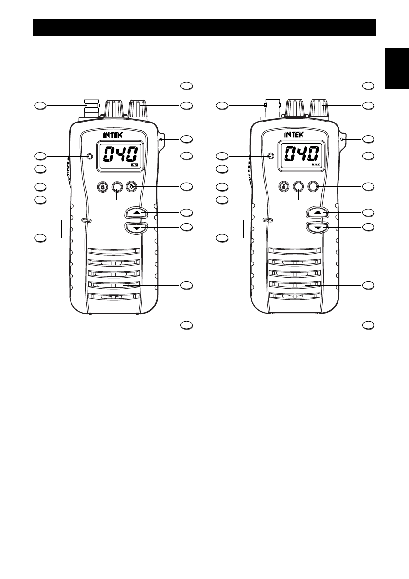
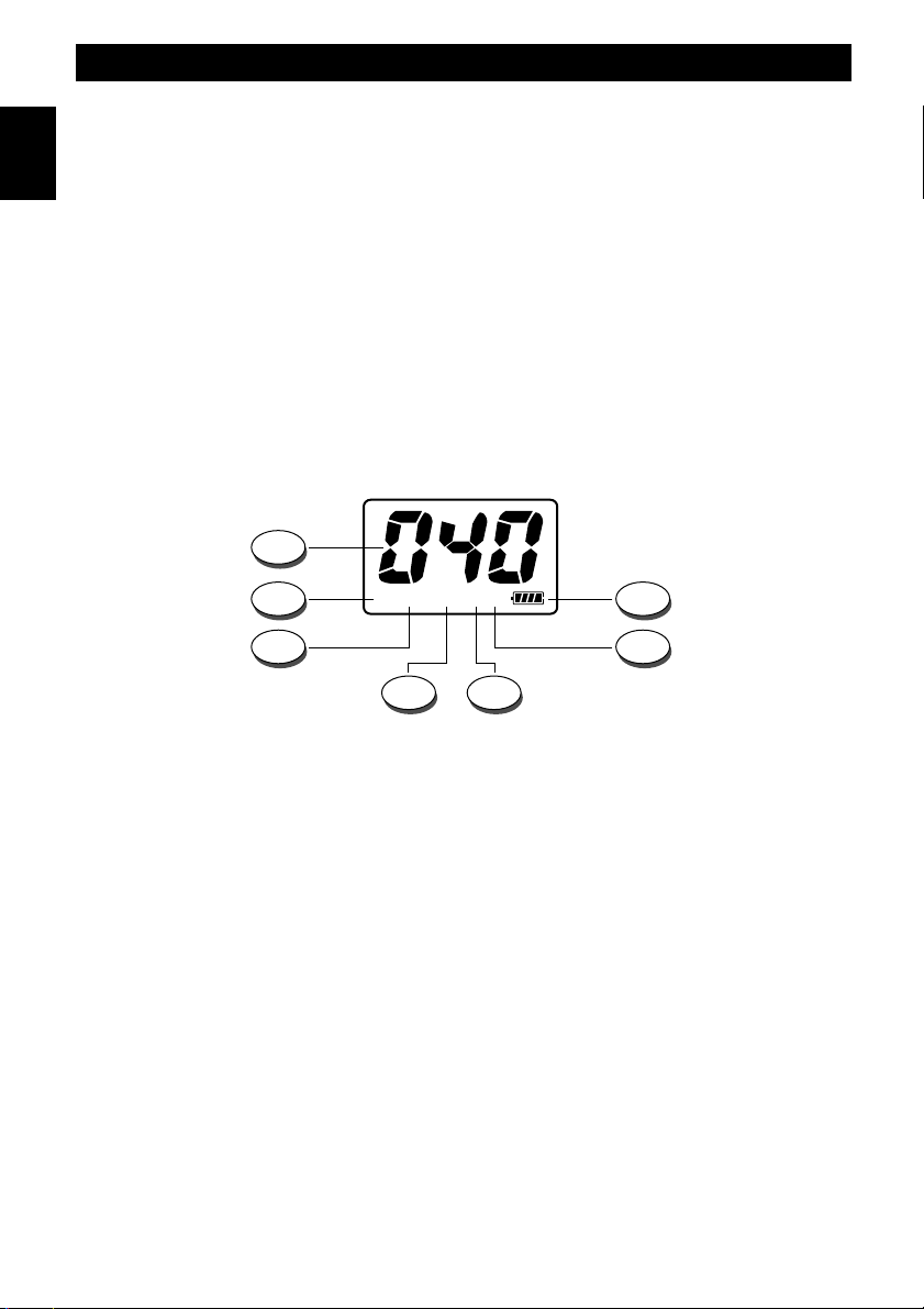
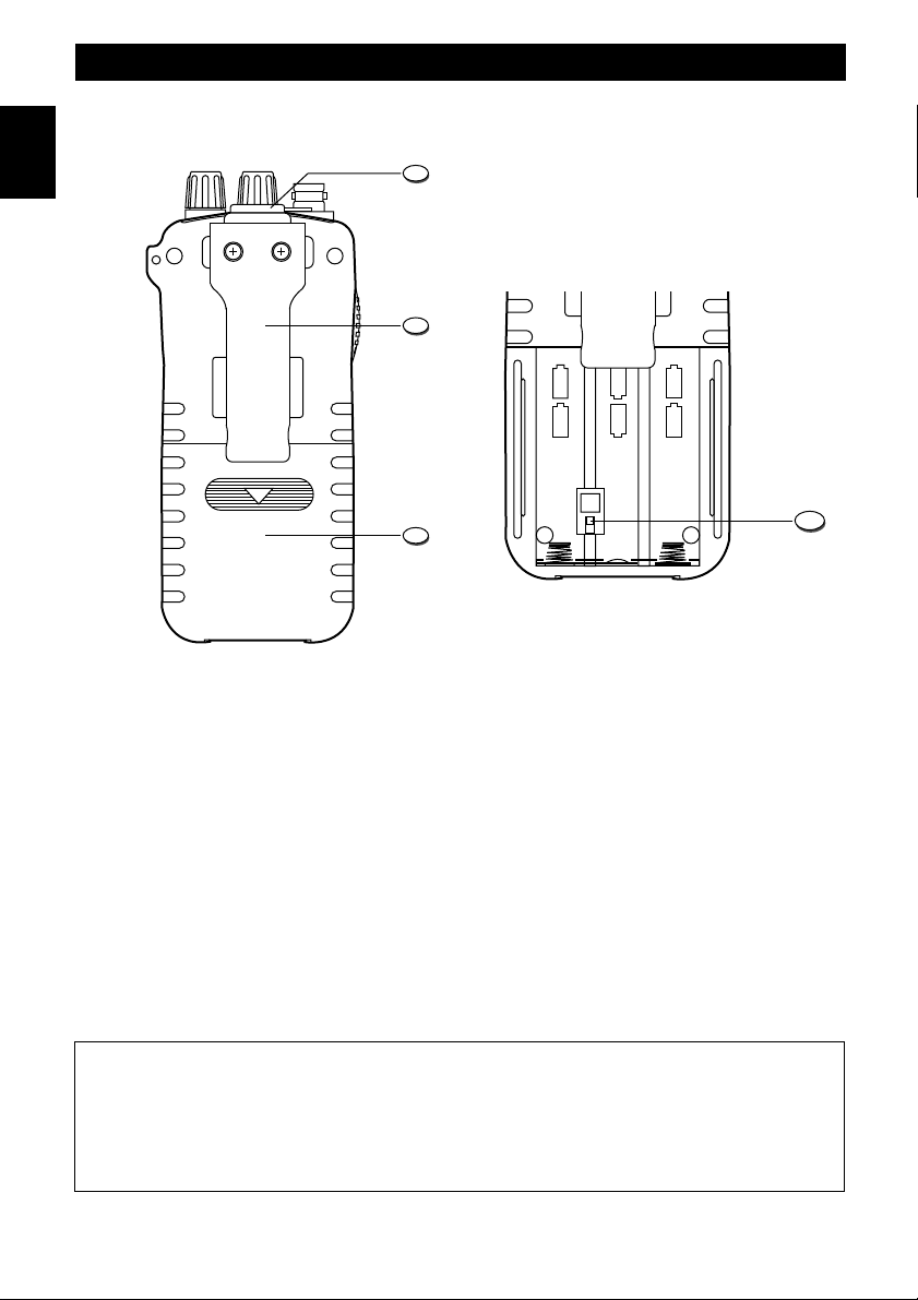
Controls, indicators and operation . . . . . . . . . . . . . . . . . . . . . . . . . . . . . . . . . . . . . . . . . . . . . . . . . . . . . . . 2 - 5
Battery operation . . . . . . . . . . . . . . . . . . . . . . . . . . . . . . . . . . . . . . . . . . . . . . . . . . . . . . . . . . . . . . . . . . . . . . . . 6
Car adaptor operation . . . . . . . . . . . . . . . . . . . . . . . . . . . . . . . . . . . . . . . . . . . . . . . . . . . . . . . . . . . . . . . . . . . . 7
Frequency bands table H-510 PLUS . . . . . . . . . . . . . . . . . . . . . . . . . . . . . . . . . . . . . . . . . . . . . . . . . . . . . . . . 8
Frequency bands table H-512 PLUS - User Information . . . . . . . . . . . . . . . . . . . . . . . . . . . . . . . . . . . . . . . . 9
Frequency band selection / programming . . . . . . . . . . . . . . . . . . . . . . . . . . . . . . . . . . . . . . . . . . . . . . . . . . 10
Table of restrictions on the use of CB transceivers . . . . . . . . . . . . . . . . . . . . . . . . . . . . . . . . . . . . . . . . . . . 10
Specifications - Optional Accessories . . . . . . . . . . . . . . . . . . . . . . . . . . . . . . . . . . . . . . . . . . . . . . . . . . . . . . 11
Table of restrictions on the use of CB transceivers . . . . . . . . . . . . . . . . . . . . . . . . . . . . . . . . . . . . . . . . . . . . I
PCB - Main Board . . . . . . . . . . . . . . . . . . . . . . . . . . . . . . . . . . . . . . . . . . . . . . . . . . . . . . . . . . . . . . . . . . . . II - III
Diagram . . . . . . . . . . . . . . . . . . . . . . . . . . . . . . . . . . . . . . . . . . . . . . . . . . . . . . . . . . . . . . . . . . . . . . . . . . . .IV - V
Block Diagram . . . . . . . . . . . . . . . . . . . . . . . . . . . . . . . . . . . . . . . . . . . . . . . . . . . . . . . . . . . . . . . . . . . . . . VI-VII
Declaration of Conformity H-510 PLUS . . . . . . . . . . . . . . . . . . . . . . . . . . . . . . . . . . . . . . . . . . . . . . . . . . . . VIII
Declaration of Conformity H-512 PLUS . . . . . . . . . . . . . . . . . . . . . . . . . . . . . . . . . . . . . . . . . . . . . . . . . . . . . IX
NOTICE !
Before using this transceiver, please check that the radio has been programmed on the frequency band,
specifications and operating modes allowed by the regulations valid in the country where the product is used. If
not, please proceed to modify the frequency band programming, as it is described in this owner’s manual. This
transceiver is factory pre-programmed on the CE European frequency band CEPT 40CH FM 4W (H-512 PLUS) or on
the E1 band 40CH AM 4W (H-510 PLUS).
It is recommended to carefully read this owner’s manual before using the product. This will also help the user to
prevent using the radio in violation of the regulations valid in the country where the product is used, as well as to
avoid any possible interferences with other services.
Congratulations!
Congratulations for selecting and purchasing an INTEK quality product. This transceiver includes a number of advanced
functions and systems, therefore it is definitely necessary to carefully read this owner’s manual before using the radio.
With a correct use of the product in accordance with the operating method described in this manual, the product will offer
a trouble free use for many years. INTEK is constantly engaged to develop and provide quality products meeting the
customers requirements, however any suggestion or comments on this product that might help us to improve quality are
warmly welcome. This transceiver has advanced hardware and software design, it includes a special multi-standard
programmable circuit, which allows to program the specifications of the radio (frequency bands, operating modes,
transmitter power) in compliance with the regulations valid in the various European countries. Therefore this product
can be used in any country of the European Community. Using this two-way radio is quite easy and only a few minutes
are required to get familiar with it. The operating method and design are the results of years of experience in the
development and production of RF communication equipment, for personal an professional use. However it is strongly
recommended to carefully read this manual in order to get the maximum performances from your transceiver.
Content of the Package
Please carefully check that all the following items are contained in the packaging :
Transceiver Carrying strap
Rubber antenna User manual
Belt clip with mounting hardware
English

- 2 -
English
Controls, Indicators and Operation
Front Panel
AM/FM CB TRANSCEIVER
MIC
H-512 PLUS
TX
UP
DN
H/L A/F
AM FM HI LOLOCK
1 3
5
6
7
8
9
10
4
2
11
MIC
TX
UP
DN
H/L
AM FM HI LOLOCK
14
15
13
12
1 3
5
6
7
8
9
10
4
2
11
15
13
12
AM CB TRANSCEIVER
H-510 PLUS
14
H-510 PLUS H-512 PLUS
1. Antenna Connector
Connect the supplied rubber antenna to this BNC connector, insert and gently turn it clockwise until blocked.
Do not overtighten. If the antenna is not or not correctly connected, damage may be caused to the radio.
2. SQ/SQL Control
SQL CONTROL (SQUELCH manual adjustment)
The SQL control allows to silent the receiver by cutting the background noise, when no signals are received. Turn the
knob clockwise until the background noise is cut. Turn the knob counter clockwise (SQUELCH opening) in order to listen
to the weakest signals.
SQ CONTROL (SQUELCH fixed setting)
The SQ function allows to automatically silent the receiver, avoding the SQUELCH manual adjustment. A fixed
SQUELCH threshold is factory pre-set. To enable the fixed SQUELCH function, turn the knob fully counter clockwise to
the SQ position, until a click noise is heard.

- 3 -
English
Controls, Indicators and Operation
3. VOL (OFF/Volume) Control
This knob switches the radio ON and OFF and it adjusts the volume control. If no signals are being received on the
operating channel, it is suggested to open the SQUELCH and adjust the volume to the desired level while listening to the
background noise.
4. Handstrap Hole
Hole to insert and attach the supplied carrying handstrap.
5. LCD Display
Large size LCD display with green color backlight function for best readability in darkness. It indicates
simultaneously all the programmed settings and all the enabled functions, such as the operating channel
number, the operating mode and 4-bar battery level indicator.
LCD Display
AM FM HI LOLOCK
E D
G
A
F
B
C
A. Channel Number
It indicates the operating channel number or the frequency band ID code.
B. Battery Level Indicator
It shows the current battery level condition.
C. LO Icon
The LO Icon (C) is lighted when the transmitter is in LOW POWER mode (1W).
D. Icona HI
The HI Icon (D) is lighted when the transmitter is in HIGH POWER mode (4W).
E. LOCK Icon
The LOCK icon (E) is lighted when the keypad lock function has been enabled.
F. FM Icon (H-512 PLUS)
The FM icon (F) is lighted when radio has been set to the FM (Frequency Modulation) operating mode.
G. AM Icon
The AM icon is lighted when radio has been set to the AM (Amplitude Modulation) operating mode.

- 4 -
English
Controls, Indicators and Operation
6. LIGHT Key (H-510 PLUS)
Press the LIGHT (6) key to backlight the LCD display, press the key again to switch OFF backlight.
A/F (AM/FM) Key (H-512 PLUS)
Use the AF key to select the AM or FM operating mode in both RX and TX. The AM/FM operating mode selection is
possible only if it is allowed by the programmed frequency band, otherwise the AM/FM selection is not possible.
7. UP (QUICK UP) Key
Shortly press the UP (9) key to increase the channel number by one channel up at every key press. By keeping this key
pressed, the quick channel selection mode will be enabled.
8. DN (QUICK DN) Key
Shortly press the DN (8) key to decrease the channel number by one channel down at every key press. By keeping this
key pressed, the quick channel selection mode will be enabled.
9. Built-in Speaker
Built-in front speaker.
10. Car Adaptor Contacts
Car adaptor contacs and fixing screw.
11. Built-in Microphone
Built-in microphone.
12. H/L Key
The transmitter RF output power is selectable in 2 levels (1.0W or 4.0W). This function is very convenient to reduce the
current drain and extend battery life when communicating within short distance. The 4W RF output power level is
available only if it is allowed by the programmed frequency band. Press H/L (12) key to select the transmitter RF output
power HI (High Power 4W) or LO (Low Power 1W). The HI (D) or LO (C) icons will appear on the LCD Display (5).
13. LOCK / Keypad Tone Key
LOCK
Press the LOCK (13) key for a few seconds to enable the keypad LOCK function. Press the key again to disable.
KEYPAD PROGRAM TONE
When a key is pressed, a beep tone is heard to confirm your command. To enable or disable this keypad program tone
press and keep pressed the LOCK (13) key while switching ON radio, by turning the VOL (3) control clockwise.
14. PTT (Push-To-Talk) Key
Press the PTT (14) key to transmit and hold it during transmission. The TX LED indicator (15) will be lighted during
transmission. Release the key at the end of your transmission to return to the receive mode.
WARNING ! Do not touch the antenna during transmission.
15. TX LED
This red color LED indicator (15) lights up when radio is in transmit mode.

- 5 -
Controls, Indicators and Operation
NI
AL
+
-
+
-
+
-
+
-
+
-
+
-
19
Rear Panel
16
17
18
16. Earset-Microphone-Charge Jack
Connect an external earset-microphone to this jack. Connect the 230VAC battery travel charger (AC-520) to this jack.
WARNING !
Use only original accessories. Connecting and using accessories other than the original ones, may cause
serious damage to the radio and will void the warranty.
Always set the volume to minimum before connecting an external earset, in order to avoid damaging the earset
or the user’s ear.
17. Belt Clip
18. Battery Door
Open this cover (18) to install or remove batteries.
19. Battery Type Selector
The battery type selector (18) is located inside the battery room. Set the switch (19) to Ni if rechargeable batteries are
used. Set the switch (19) to AL if alkaline batteries are used.
WARNING !
Do never try to open the cabinet of the radio. No user serviceable parts are inside the cabinet. Tampering or
modifying the circuit of the radio or its original factory adjustment may cause damage to the product, may change
the electrical specifications and will void the warranty. If service is required, please refer only to a qualified and
authorized service center.
English

- 6 -
Battery Operation
Installing and Checking Batteries
Slide down and remove the battery door (18) to access the battery room. Set the battery type switch (19) according to
the type of used batteries (Ni for rechargeable batteries and AL for alkaline batteries). Install 6 x AA size alkaline
batteries or rechargeable batteries and pay attention to install it with the correct polarity as indicated in the battery
room. Switch ON radio by turning the OFF/VOL (3) control and check the battery level on the battery level indicator
(B), 4 bars mean full charge, 3 bars mean normal charge, 2 bars mean half charge and 1 bar means low battery
condition. If no bars appear, batteries must be immediately replaced or recharged. Please refer to the following item
BATTERY CHARGING.
Battery Charging
If the battery level indicator (B) shows a low battery condition, switch OFF the radio and connect the battery travel
charger mod. AC-520 to the CHARGE jack (16), then plug it into the 230VAC outlet. To obtain the maximum
performance from the batteries, recharge them only when they are fully discharged. The charging time depends on the
capacity of the used batteries, it is approximately 12 hours for one set of Ni-MH batteries (1200-1500mAh). When the
charging time has expired, unplug the charger from the AC outlet and then disconnect it from the radio.
WARNING !
1. Only the Ni-MH (or Ni-CD) batteries may be recharged.
2. Do never try to recharge alkaline batteries, as this might cause damage to the radio or explosion of the
batteries.
3. Set the battery type selector (19) to Ni.
4. Always switch OFF radio before starting the battery charging process.
5. Do not recharge batteries for more than 13-14 hours, in order to avoid overcharge or overheating, which could
cause damage to the radio.
6. Use only the enclosed battery charger or original INTEK battery chargers.
English

Car Adaptor Operation
Operation of the Car Adaptor (CAR-520)
This handheld radio can be turned into a mobile transceiver by connecting the Car Adaptor CAR-520. The Car Adaptor
will supply a regulated DC power to the radio, directly from the car cigarette lighter plug as well as the connection for an
external antenna. Install the Car Adaptor as follows :
1. Remove the rubber antenna from the radio.
2. Connect the Car Adaptor to the radio, as showed in the below picture.
3. Lock the Car Adaptor to the radio by turning the knob (20) in the LOCK direction as indicated by the arrow. Do not
overtighten this screw.
4. Connect the cigarette lighter adaptor into the cigarette lighter plug in the vehicle (12VDC).
5. Connect an external antenna to the SO-239 antenna connector of the Car Adaptor.
LOCK
18
20
- 7 -
English

- 8 -
Frequency Bands Table H-510 PLUS
The INTEK H-510 PLUS transceiver includes an advanced multi-standard programmable circuit design, which allows to
program the radio in accordance with the frequency band, operating modes, transmitter RF output power in full
compliance with the local regulations of the country where the radio will be used. A total of 5 programmable frequency
bands are available, as per the following table :
WARNING ! The radio has been factory pre-programmed on the E1 (40CH AM 4W) frequency band, as this standard is
currently accepted by some countries (Italy and Spain). Please refer to the information table at page I(Restrictions on
the use of CB transceivers).
FREQUENCY BAND
ID CODE COUNTRY SPECIFICATIONS
(Channels, Operating Modes, TX Power)
E1 ITALY/SPAIN
40CH AM
I2 ITALY
36CH AM
DE GERMANY
12CH AM 1W
EU EUROPE/FRANCE
40CH AM 1W
PL POLAND
40CH AM POLISH FREQUENCIES
English

Frequency Bands Table H-512 PLUS - User Information
- 9 -
Frequency Bands Table H-512 PLUS
The INTEK H-512 PLUS transceiver includes an advanced multi-standard programmable circuit design, which allows to
program the radio in accordance with the frequency band, operating modes, transmitter RF output power in full
compliance with the local regulations of the country where the radio will be used. A total of 8 programmable frequency
bands are available, as per the following table :
WARNING ! The radio has been factory pre-programmed on the CE (CEPT 40CH FM 4W) frequency band, as this
standard is currently accepted by all the European countries. Please refer to the information table at page I
(Restrictions on the use of CB transceivers).
User Information
in accordance with art. 13 of the Legislative Decree of 25th July 2005, no. 15 ”Implementation of Directives 2002/95/EC,
2002/96/EC and 2003/108/EC, relative to reduction of the use of hazardous substances in electrical and electronic
equipment, in addition to waste disposal”.
The crossed bin symbol shown on the equipment indicates that at the end of its working life the product must
be collected separately from other waste.
The user must therefore take the above equipment to the appropriate differentiated collection centres for
electronic and electro technical waste, or return it to the dealer when purchasing a new appliance of
equivalent type, in a ratio of one to one.
Appropriate differentiated waste collection for subsequent recycling, treatment and environment-friendly disposal of the
discarded equipment helps to prevent possible negative environmental and health effects and encourages recycling of
the component materials of the equipment.
Illegal disposal of the product by the user will be punished by application of the administrative fines provided for by the
legislative decree no. 22/1997 (article 50 and following of the legislative decree no. 22/1997).
FREQUENCY BAND
ID CODE COUNTRY SPECIFICATIONS
(Channels, Operating Modes, TX Power)
E1 ITALY/SPAIN
40CH AM / FM 4W
I2 ITALY
36CH AM / FM 4W
DE GERMANY
80CH FM 4W - 12CH AM 1W
D2 GERMANY
40CH FM 4W - 12CH AM 1W
EU EUROPE/FRANCE
40CH FM 4W - 40CH AM 1W
CE CEPT
40CH FM 4W
UUK
40CH FM 4W UK FREQUENCIES
40CH FM 4W CEPT FREQUENCIES
PL POLAND
40CH AM / FM 4W POLISH FREQUENCIES
English

Frequency Bands Selection / Programming
- 10 -
Frequency Band Selection / Programming
The radio must be programmed and used exclusively on the frequency band allowed by the regulations of the country
where the radio will be used. In order to program the frequency band, please refer to the following instructions :
1. Turn OFF radio.
2. Press and keep pressed the PTT (14) key while switching ON radio, by turning the OFF/VOL (3) control
clockwise.
3. The current programmed frequency band ID code (A) appears on the LCD.
4. Using the UP (7) or DN (8) keys, select a new frequency band ID code.
5. Shortly press the PTT (14) key to confirm and store.
UK/CE CHANNELS SELECTION (FREQUENCY BAND "U") (H-512 PLUS)
If the frequency band "U" (UK band) has been selected, all channels can be scrolled using the channel keys. When a
UK frequency channel will be selected the display (5) will show the channel number and the indication "U". When a
CEPT frequency channel will be selected the display (5) will show the channel number and the indication "C".
Table of Restrictions on the Use of CB Transceivers (page I)
The following information are to be considered only just as an indication. They are believed to be correct at the time of
printing this operating manual. It is however the user’s responsibility to check that, in the country where radio is used, the
regulations for the use of CB transceivers have not been modified. User is therefore suggested to contact the local
dealer or local authority, in order to check the current regulations for the use of CB transceivers, before operating this
product. The manufacturer does not take any responsibility if the product is used in violation of the regulations of the
country where the product is used.
Addendum (Updated information on national restrictions)
BELGIUM, UK, SPAIN, SWITZERLAND
In order to use this transceiver in Belgium, UK, Spain and Switzerland, residence must have an individual licence. Users
coming from abroad may freely use the radio in FM mode, while in order to use it in AM mode they must hold a licence
released in their own country.
ITALY
Foreigners arriving in Italy must get an Italian authorization.
AUSTRIA
Austria does not allow using multi standard programmable CB radios. It is recommended to carefully follow this
directives and not to use the product in the Austrian territory.
GERMANY
Along some border areas in Germany, the radio can not be used as a base station from channel 41 to channel 80. Refer
to local authority (notification office) for details.
English

Specifications - Optional Accessories
- 11 -
Specifications
General
Channels Refer to the frequency bands table at pages 8-9
Frequency band 27 MHz Citizen Band
Frequency control P.L.L.
Operatine temperature -10°/+55°C
DC input voltage 9.0V (6 x AAA 1.5V alkaline battery)
7.2V (6 x AAA 1.2V Ni-MH battery)
Size 68 (L) x 146 (H) x 38 (D) mm
Weight 185 gr. (without batteries and antenna)
Receiver
System Double conversion, CPU controlled super-eterodine
IF 1°10.695 MHz / 2°455 KHz
Sensitivity 0.5uV for 20dB SINAD (FM) (H-512 PLUS)
0.7uV for 20dB SINAD (AM)
Audio output 0.3W at 8 ohm
Audio distorsion <8% at 1 KHz
Image rejection 61dB
Adjacent channel 61dB
Signal/noise ratio 45dB
Current drain 70mA (stand-by)
Transmitter
System CPU controlled P.L.L. systhesizer
Maximum RF power 4W at 9.0Vdc
Modulation AM/FM (H-512 PLUS)
AM
Impedance 50 ohm unbalanced
Current drain 1500mA (at no modulation)
Optional Accessories
AC-520 230VAC Battery Charger
LC-512 Soft Carrying Case
CAR-520 Mobile Car Adaptor
MR-1500AA 1500mAh Ni-MH Battery
English

Indice - Introduzione - Contenuto della confezione
- 12 -
Indice - Introduzione - Contenuto della confezione . . . . . . . . . . . . . . . . . . . . . . . . . . . . . . . . . . . . . . . . . . . 12
Descrizione dei comandi, indicatori e funzionamento . . . . . . . . . . . . . . . . . . . . . . . . . . . . . . . . . . . . . . 13-16
Utilizzo delle batterie . . . . . . . . . . . . . . . . . . . . . . . . . . . . . . . . . . . . . . . . . . . . . . . . . . . . . . . . . . . . . . . . . . . . 17
Utilizzo dell' adattatore veicolare . . . . . . . . . . . . . . . . . . . . . . . . . . . . . . . . . . . . . . . . . . . . . . . . . . . . . . . . . . 18
Tabella bande di frequenza H-510 PLUS . . . . . . . . . . . . . . . . . . . . . . . . . . . . . . . . . . . . . . . . . . . . . . . . . . . . 19
Tabella bande di frequenza H-512 PLUS - Avviso agli utenti . . . . . . . . . . . . . . . . . . . . . . . . . . . . . . . . . . . . 20
Selezione / programmazione della banda di frequenza . . . . . . . . . . . . . . . . . . . . . . . . . . . . . . . . . . . . . . . . 21
Tabella delle restrizioni all' uso dei ricetrasmettitori CB . . . . . . . . . . . . . . . . . . . . . . . . . . . . . . . . . . . . . . . 21
Caratteristiche tecniche - Accessori opzionali . . . . . . . . . . . . . . . . . . . . . . . . . . . . . . . . . . . . . . . . . . . . . . . 22
Note . . . . . . . . . . . . . . . . . . . . . . . . . . . . . . . . . . . . . . . . . . . . . . . . . . . . . . . . . . . . . . . . . . . . . . . . . . . . . . . . . . 23
Tabella delle restrizioni all' uso dei ricetrasmettitori CB . . . . . . . . . . . . . . . . . . . . . . . . . . . . . . . . . . . . . . . . I
Circuito stampato Main Board . . . . . . . . . . . . . . . . . . . . . . . . . . . . . . . . . . . . . . . . . . . . . . . . . . . . . . . . . . .II-III
Schema elettrico . . . . . . . . . . . . . . . . . . . . . . . . . . . . . . . . . . . . . . . . . . . . . . . . . . . . . . . . . . . . . . . . . . . . . . IV-V
Schema a blocchi . . . . . . . . . . . . . . . . . . . . . . . . . . . . . . . . . . . . . . . . . . . . . . . . . . . . . . . . . . . . . . . . . . . VI-VII
Dichiarazione di ConformitàH-510 PLUS . . . . . . . . . . . . . . . . . . . . . . . . . . . . . . . . . . . . . . . . . . . . . . . . . . VIII
Dichiarazione di ConformitàH-512 PLUS . . . . . . . . . . . . . . . . . . . . . . . . . . . . . . . . . . . . . . . . . . . . . . . . . . . IX
IMPORTANTE !
Prima di utilizzare la ricetrasmittente, verificare che la stessa sia programmata per operare sulla banda di
frequenza e nei modi previsti dalle norme di legge in vigore nel paese in cui la radio viene utilizzata. Diversamente
procedere alla modifica della programmazione, come indicato in questo manuale di istruzioni. La radio èpre-
programmata sulla banda CEPT 40CH FM 4W (H-512 PLUS) o sulla banda E1 40CH AM 4W (H-510 PLUS).
Si raccomanda di leggere attentamente questo manuale d' uso prima di utilizzare il prodotto. Questo anche per
evitare di utilizzare la radio al di fuori dei limiti previsti dalle norme di legge in vigore nel paese dove il prodotto
viene utilizzato e per evitare ogni possibile interferenza con altri servizi.
Congratulazioni !
Congratulazioni per aver scelto ed acquistato un prodotto di qualitàINTEK. Questo ricetrasmettitore dispone di numerose
funzioni avanzate e alcuni dispositivi esclusivi. Con un uso corretto secondo quanto èindicato nel manuale di istruzioni, l'
apparecchio garantiràun servizio senza problemi per molti anni. Ci impegniamo costantemente a fornire prodotti di
qualitàche rispondano alle vostre esigenze, ma siamo comunque sempre molto interessati a ricevere eventuali vostri
commenti o suggerimenti su questo prodotto. Questo ricetrasmettitore ha caratteristiche tecniche di hardware e
software molto avanzate e dispone di un circuito di tipo Multi Standard programmabile che consente di configurare i
vari parametri dell' apparecchio (bande di frequenza, modi operativi, potenza del trasmettitore) in modo conforme alle
norme di legge in vigore nei vari paesi della ComunitàEuropea. Questa radio èquindi utilizzabile in un qualsiasi paese
della ComunitàEuropea. L' utilizzo di questo apparato éestremamente semplice; solo pochi minuti sono necessari per
prenderne familiarità. Le modalitàoperative dei comandi e delle funzioni, sono il risultato di anni di esperienza nel
campo dei ricetrasmettitori, per uso personale e professionale. Per ottenere le massime prestazioni dal ricetrasmettitore,
consigliamo di prendere attentamente visione del manuale prima di iniziarne l' uso.
Contenuto della confezione
Controllare attentamente che la confezione contenga i seguenti componenti :
Ricetrasmettitore Cinghietta di trasporto
Antenna in gomma Manuale di istruzioni
Clip da cintura con viti di fissaggio
Italiano

Descrizione dei comandi, indicatori e funzionamento
- 13 -
AM/FM CB TRANSCEIVER
MIC
H-512 PLUS
TX
UP
DN
H/L A/F
AM FM HI LOLOCK
1 3
5
6
7
8
9
10
4
2
11
MIC
TX
UP
DN
H/L
AM FM HI LOLOCK
14
15
13
12
1 3
5
6
7
8
9
10
4
2
11
15
13
12
AM CB TRANSCEIVER
H-510 PLUS
14
Pannello frontale
1. Presa per antenna
Connettore BNC per il collegamento dell’antenna in gomma in dotazione. Inserire e ruotare gentilmente in senso orario
per bloccare, non forzare. Il mancato inserimento puòcausare danni al ricetrasmettitore.
2. Manopola SQ/SQL
COMANDO SQL (regolazione manuale SQUELCH)
Il comando SQL permette di silenziare il ricevitore, eliminando il rumore (fruscio) di fondo in assenza di segnali. Ruotare
la manopola in senso orario sino a quando scompare il rumore di fondo. Ruotare la manopola in senso antiorario
(apertura dello SQUELCH) per ascoltare i segnali piùdeboli.
COMANDO SQ (regolazione fissa SQUELCH)
E' disponibile la funzione SQ per silenziare il ricevitore in modo automatico, senza eseguire la regolazione manuale dello
SQUELCH. Una regolazione fissa dello SQUELCH èpre-impostata in origine. Per impostare la funzione SQ, ruotare la
manopola completamente in senso antiorario fino a farla scattare in posizione SQ.
H-510 PLUS H-512 PLUS
Italiano

Descrizione dei comandi, indicatori e funzionamento
- 14 -
3. Manopola OFF/VOL
Manopola di accensione e spegnimento della radio. Permette la regolazione del volume di ascolto. In assenza di segnali
sul canale in uso, si consiglia di aprire lo SQUELCH e quindi di regolare il volume al livello desiderato utilizzando come
riferimento il rumore (fruscio) di fondo.
4. Foro per laccetto
Foro per l’inserimento della cinghietta di trasporto.
5. Display LCD
Ampio display LCD di tipo retro-illuminato in colore verde, per la massima leggibilitàanche nell’oscurità,
indica simultaneamente tutte funzioni e i dispositivi attivati, tra cui la lettura del numero del canale, il modo
operativo e l' indicatore livello batteria a 4 segmenti.
AM FM HI LOLOCK
E D
G
A
F
B
C
Display LCD
A. Indicazione del canale
L' indicazione consente la lettura del numero del canale in uso o della banda di frequenza selezionata.
B. Indicazione livello batteria
Visualizza lo stato di carica delle batterie a 4 livelli.
C. Icona LO
L' icona LO (C) èaccesa quando il ricetrasmettitore èin modalitàbassa potenza (1W).
D. Icona HI
L' icona HI (D) èaccesa quando il ricetrasmettitore èin modalitàalta potenza (4W).
E. Icona LOCK
L' icona LOCK (E) èaccesa quando la funzione di blocco tastiera èattiva.
F. Icona FM (H-512 PLUS)
L' icona FM (F) èaccesa quando il ricetrasmettitore riceve e trasmette in modo FM (modulazione di frequenza).
G. Icona AM
L' icona AM (G) èaccesa quando il ricetrasmettitore riceve e trasmette in modo AM (modulazione di ampiezza).
Italiano

Descrizione dei comandi, indicatori e funzionamento
- 15 -
6. Tasto LIGHT (H-510 PLUS)
Premendo il tasto LIGHT (6) èpossibile accendere o spegnere la retroilluminazione del display LCD (5).
Tasto A/F (AM/FM) (H-512 PLUS)
Questo tasto permette di selezionare il modo operativo AM o FM in ricezione e trasmissione. La selezione del modo
AM/FM èabilitata solamente se ammessa dalla banda di frequenza/modo programmata, diversamente la selezione non
èpossibile.
7. Tasto UP (Quick UP)
Questo tasto permette la selezione dei canali in ordine crescente. Mantenendo premuto questo tasto, la selezione dei
canali avverràin modo rapido.
8. Tasto DN (Quick DN)
Questo tasto permette la selezione dei canali in ordine decrescente. Mantenendo premuto questo tasto, la selezione dei
canali avverràin modo rapido.
9. Altoparlante incorporato
Altoparlante entro contenuto.
10. Attacco per adattatore veicolare
Attacco per il fissaggio dell’adattatore per uso veicolare (Car Adaptor).
11. Microfono
Microfono di tipo Electret, entro contenuto.
12. Tasto H/L
La potenza di uscita del trasmettitore puòessere selezionata in 2 livelli (1.0W o 4W). Questa funzione èmolto utile per
ridurre il consumo delle batterie durante comunicazioni a breve distanza. Il livello di potenza 4W èattivo solo nelle
bande di frequenza ove questo livello di potenza èammesso. Premere questo tasto per selezionare il livello di potenza
desiderato HI (alta potenza 4W) o LO (bassa potenza 1W). Sul display LCD compariranno le icone HI (D) o LO (C).
13. Tasto LOCK (blocco tastiera) / Tono di tastiera
FUNZIONE LOCK
Mantenendo premuto questo tasto per circa 2 secondi viene inserita la funzione di blocco tastiera. Per disinserire questa
funzione ripetere l’operazione.
FUNZIONE TONO DI TASTIERA
Ogni qualvolta viene premuto un tasto della radio, un tono beep èprodotto per confermare il comando inserito.
Questa nota musicale puòessere attivata o disattivata dall’utente, accendendo la radio mantenendo premuto il tasto
LOCK (13).
14. Tasto PTT (Push-To-Talk)
Tasto di trasmissione. Premere per trasmettere e mantenere premuto durante la trasmissione. L' indicatore LED di
trasmissione TX (15) rimarràacceso durante la trasmissione. Rilasciare il tasto PTT (14) per ritornare in modalità
ricezione. ATTENZIONE ! Non toccare l' antenna durante la trasmissione.
15. Indicatore LED TX
Questo indicatore LED luminoso di colore rosso èacceso quando il ricetrasmettitore èin modalitàtrasmissione.
Italiano

Descrizione dei comandi, indicatori e funzionamento
- 16 -
NI
AL
+
-
+
-
+
-
+
-
+
-
+
-
19
Pannello posteriore
16
17
18
16. Presa Mike-Speaker / ricarica
Presa per il collegamento di un microfono-altoparlante esterno e del carica batterie da parete 230VAC in dotazione.
AVVERTENZA ! Usare solo accessori originali. Collegare ed utilizzare accessori diversi da quelli originali può
causare gravi danni al ricetrasmettitore ed inoltre la perdita della garanzia.
Ridurre sempre il livello di volume al minimo prima di collegare una cuffia o microfono esterni e aumentarlo
gradatamente per evitare di danneggiare l'accessorio o l' udito dell' operatore.
17. Clip da cintura
18. Coperchio vano batterie
Coperchio dell’alloggiamento delle batterie.
19. Selettore batterie utilizzate
Deviatore, posto all’interno del vano batterie, utilizzato per la selezione del tipo di batterie utilizzate: Ni per batterie
ricaricabili e AL per batterie alkaline.
IMPORTANTE !
Non tentare mai di aprire il contenitore del ricetrasmettitore. All' interno dell' apparecchio non vi sono parti utili o
utilizzabili dall' utente. Interventi o manomissioni del circuito interno della radio possono causare danni alla stessa
o modificarne le caratteristiche tecniche ed inoltre violano e invalidano il diritto alla garanzia. In caso di interventi
tecnici, rivolgersi esclusivamente ad tecnico o ad un centro di assistenza autorizzato.
Italiano

Utilizzo delle batterie
- 17 -
Italiano
Installazione e controllo delle batterie
Rimuovere il coperchio batterie (18) sfilandolo nella direzione della freccia indicata sullo stesso. Selezionare il tipo di
batterie che verràutilizzato tramite il deviatore (19) posto nel vano batterie. Selezionare Ni per le batterie ricaricabili o
AL per le batterie alkaline. Inserire 6 pile tipo AA alkaline oppure oppure batterie ricaricabili al Ni-MH, rispettando la
corretta polarità, come indicato nel vano batterie. Accendere l' apparecchio, ruotando la manopola ON/OFF-VOLUME
(3) in senso orario e controllare l' indicatore del livello di carica delle batterie (B). 4 barre indicano la piena carica delle
batterie, 3 barre indicano normale livello di carica, 2 barre indicano metàlivello di carica e 1 barra indica basso livello di
carica. Se l' indicatore di livello delle batterie non presenta nessuna barra, le stesse devono essere immediatamente
sostituite o ricaricate. Per il corretto procedimento, fare riferimento al paragrafo RICARICA BATTERIE.
Ricarica batterie
Se l' indicatore (B) del livello delle batterie indica un basso livello di carica, spegnere il ricetrasmettitore e collegare il
caricatore da muro mod. AC-520 alla presa di ricarica Charge (16) e successivamente alla presa di corrente 230VAC.
Per ottenere il massimo rendimento, le batterie dovrebbero essere ricaricate solo se completamente scariche. Il tempo
di carica dipende dalla capacitàdelle batterie utilizzate; il tempo di carica normale, per un set di batterie al Ni-MH (1200-
1500 mAh) édi circa 12 ore. A processo di ricarica ultimato, estrarre il caricabatterie dalla presa di corrente e
successivamente scollegarlo dalla radio.
AVVERTENZE !
1. Possono essere ricaricate solo batterie di tipo Ni-MH (o Ni-CD).
2. Non tentare mai di ricaricare le batterie alkaline, al fine di evitare danni alla radio o l' esplosione delle stesse.
3. Assicurarsi che il selettore del tipo di batterie utilizzato (19) sia posizionato su Ni.
4. Spegnere sempre il ricetrasmettitore prima di iniziare il processo di ricarica.
5. Non ricaricare mai le batterie per piùdi 13-14 ore, per evitare la sovraccarica o il surriscaldamento delle stesse,
con conseguenti danni alla radio.
6. Utilizzare solo il caricabatterie in dotazione con il prodotto o i carica batterie originali INTEK.

Utilizzo dell' adattatore veicolare
- 18 -
Italiano
Utilizzo dell' adattatore per uso veicolare (CAR-520)
L' adattatore CAR-520 permette di trasformare il ricetrasmettitore portatile in apparato veicolare in quanto consente di
alimentare la radio direttamente dalla presa accendisigari del veicolo e di collegarlo ad un' antenna esterna.
Installare l' adattatore veicolare procedendo come segue :
1. Togliere l' antenna in gomma dalla radio.
2. Collegare l' adattatore veicolare alla radio come mostrato nel disegno. Fare combaciare la contattiera della radio
con quella dell' adattatore veicolare ed inserire i 2 dentelli di plastica nei 2 fori predisposti.
3. Avvitare la ghiera (20) alla radio, nel senso indicato dalla scritta LOCK.
4. Collegare lo spinotto accendisigari alla presa accendisigari del veicolo (12VDC).
5. Collegare un' antenna esterna alla presa SO-239 dell' adattatore veicolare.
LOCK
18
20

Tabella bande di frequenza H-510 PLUS
Il ricetrasmettitore INTEK H-510 PLUS dispone di un avanzato circuito multi-standard programmabile, che consente di
programmare la banda di frequenza, i parametri e i modi operativi in conformitàcon le norme del paese in cui viene
utilizzato l’apparecchio. Sono disponibili n. 5 bande programmabili, come dalla seguente tabella :
ATTENZIONE ! Il ricetrasmettitore èstato pre-programmato all’origine sulla banda di frequenza con codice paese E1
(40CH AM 4W), in quanto questo standard èattualmente riconosciuto in alcuni paesi (Italia e Spagna). Vedere la tabella
delle informazioni alla pag. I(Restrizioni all’uso dei ricetrasmettitori CB).
CODICE BANDA
DI FREQUENZA PAESE
SPECIFICHE
(Canali, modi operativi, potenza TX)
E1 ITALIA/SPAGNA
40CH AM
I2 ITALIA
36CH AM
DE GERMANIA
12CH AM 1W
EU EUROPA/FRANCIA
40CH AM 1W
PL POLONIA
40CH AM FREQUENZE POLACCHE
- 19 -
Italiano
Other manuals for H-510 PLUS
1
This manual suits for next models
1
Table of contents
Languages:
Other Intek Transceiver manuals

Intek
Intek M-795 User manual

Intek
Intek MT-174W10 User manual

Intek
Intek HR-5500 User manual

Intek
Intek SL-02 User manual

Intek
Intek M-550 Power User manual

Intek
Intek KT-950EE User manual

Intek
Intek KT-930EE User manual

Intek
Intek MT-4040 User manual

Intek
Intek M-120 PLUS User manual

Intek
Intek seatec-5 User manual

Intek
Intek M-490 Plus User manual

Intek
Intek KT-355EE User manual

Intek
Intek HR-200S User manual

Intek
Intek KT-380EE User manual

Intek
Intek KT-370EE User manual

Intek
Intek M-490 Plus User manual

Intek
Intek M-130 PLUS User manual

Intek
Intek KT-980HP User manual

Intek
Intek HR-2800 User manual

Intek
Intek M-899 VOX User manual