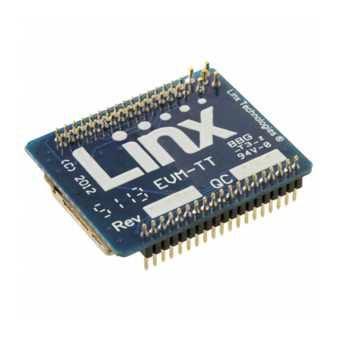
Linx NT Series User manual

–1 –
Introduction
The NT Series transceiver’s transparent data pipe is ideal for applications
that use custom protocols or legacy protocols such as PWM that are not
compatible with a standard transmission format. However, the NT Series
also has an internal packet generator for applications that don’t need a
custom protocol and don’t have the time or warrant the effort of creating
a protocol.
The packet generator takes the data presented by the user and combines
it with a preamble, SYNC word and a CRC value to create a packet. This
packet is suitable for transmission in the noisy RF environment. On the
receiving side, the packet generator validates the received packets and
presents the received data to the user if the packets arrived intact.
The internal packet generator is accessed through the module’s
Command Data Interface (CDI). The CDI is a standard UART interface
that is compatible with UARTs in a wide variety of off-the-shelf
microcontrollers. The standard UART data structure is not robust enough
for the noisy RF environment, so a protocol is required to protect the data
and ensure that it is received correctly. The module’s UART interface and
internal packet generator combine to create a wireless UART and allow
the designer to bypass protocol development.
Packet Mode Data Structure
Figure 1 shows the packet structure used by the NT Series.
The preamble is used to “clear the pipe.” It is a repeating pattern
(typically 101010) that can be distinguished from random noise. It allows
the receiver circuitry to lock on to the signal and center itself without
sacrificing any data.
The SYNC word is a fixed pattern of 3 bytes that identifies the packet as
belonging to the system and allows the receiver to synchronize to the
incoming data. It must match what is expected or the packet is
rejected.
NT Series Transceiver Wireless UART
Reference Guide RG-00102
PreambleSYNC Word PayloadCRC
8 Bytes 3 Bytes 1 to 96 Bytes 2 Bytes
Figure 1: NT Series Transceiver Packet Mode Data Structure
4/25/12

–2 –
The payload is the data to be transferred. It can be from 1 to 96 bytes
long depending on what the application needs.
The Cyclic Redundancy Check (CRC) is a data verification value that is
calculated on the transmitted packet. The receiver performs the same
calculation and if its result matches the value that was received in the
packet then the packet is declared good.
Connecting the Command Data Interface
The Packet Mode interface uses eight lines (described in Figure 2) on the
module (Figure 3).
Pulling the Transparent or Packet Select (TRPT / PKT) line low on power
up places the module into Packet Mode. The state of this line is checked
once on power up. It can be hardwired to ground.
Pulling the Command Data Type (CMD_DATA_TYPE) line high tells
the module that the data coming in on the UART should be sent to the
packet generator. If this line is low, the data is interpreted as command
data for configuring the module. Please see the Command Data
Interface Reference Guide for information on the module’s CDI. This line
can be controlled by a microcontroller to switch between Packet Mode
and configuration. The line is checked as soon as serial data is received
on the CMD_DATA_IN line.
GND
NC
GND GND
NC
NC
GND
DATA_IN
DATA_OUT
NC
NC
NC
GND
NC
GND
ANTENNA
1
2
3
4
5
6
7
83
7
38
39
40
41
42
43
44
TRPT/PKT
CHN_SEL0
GND GND
NC
NC
CMD_DATA_BAUD
CMD_DATA_TYPE
CMD_DATA_OUT
READY
CHN_SEL1
CHN_SEL2
LVL_ADJ
NC
NC
NC
9
10
11
12
13
14
15
16
29
30
31
32
33
34
35
36
GND
T/R_SEL
BAUD0 STANDBY
VCC
POWER_DOWN
GND
BAUD1
RSSI
GND
GND
CMD_DATA_IN
17
18
19
20
21
22
23
24
25
26
27
28
Figure 3: NT Series Transceiver Pinout (Top View)
NT Series Transceiver Pin Descriptions
Pin # Name Description
9 TRPT / PKT1
Transparent / Packet data select. Pull high or float for
Transparent Mode, pull low for Packet Mode. This line is
checked once on power up.
19 BAUD01Baud Rate Select 0. This line and BAUD1 set over-the-air
data rate and filter bandwidths.
20 BAUD11Baud Rate Select 1. This line and BAUD0 set over-the-air
data rate and filter bandwidths.
15 READY
Ready. This line is low when the transceiver is ready to
communicate and high when it is busy. This line can be
used for hardware flow control when using the
Command Data Interface.
27 CMD_DATA_IN
Command Data In. This line is the input for command
data to set up the module or packet data to be
packetized and transmitted.
39 CMD_DATA_OUT
Command Data Out. This line outputs the command
data to set up the module or packet data that has been
received.
30 CMD_DATA_TYPE
Command Data Type. This line sets the data input
through the Command Data Interface as either command
data or packet data. Pull low for command data; pull high
for packet data.
31 CMD_DATA_BAUD
Command Data Baud. This line sets the baud rate of the
Command Data Interface. Pull low for 9,600bps; pull high
for 57,600bps. This line is checked once on power up.
1- These lines have an internal 100kΩpull-up resistor
Figure 2: NT Series Transceiver Pin Descriptions
NT Series Wireless UART
Reference Guide RG-00102

–3 –
The CMD_DATA_TYPE line should be set prior to sending serial data to
the module and can be changed as soon as the READY line changes.
Command Data In (CMD_DATA_IN) and Command Data Out
(CMD_DATA_OUT) are the serial interface lines. The data format follows
standard UART conventions of 8 data bits, 1 start bit, 1 stop bit and no
parity. The UART voltage levels are mark (1) = VCC and space (0) = GND.
The Command Data Baud (CMD_DATA_BAUD) line sets the baud rate of
the serial interface to either 9,600bps (low) or 57,600bps (high). This line
is checked on power up and can be hardwired.
In Packet Mode, the states of the BAUD0 and BAUD1 lines set the
over-the-air baud rate as shown in Figure 4. This does not affect the
baud rate of the CDI serial interface. Using a lower baud rate results in
better range. This can be configured through the CDI or hardwired.
The Ready output (READY) can be used for simple hardware flow control
similar to the Clear To Send (CTS) line in traditional serial interfaces.
This output is logic low when the module is ready for use and logic high
when it’s busy. In Packet Mode, it goes high when the internal buffer
reaches 96 bytes, indicating that the host application should stop the
data stream. This makes it straightforward to send streaming data. The
line can be ignored to send bursts of data that are less than 96 bytes
each while waiting enough time for the NT to transfer the data over the air
and be ready for more serial data. This time can be measured using the
READY pin.
NT Series Transceiver Packet Mode Baud Selection
Baud Band BAUD1 BAUD0 Baud Rate (kbps)
0 0 0 19.2
1 0 1 57.6
2 1 0 153.6
3 1 1 300
Figure 4: NT Series Transceiver Packet Mode Baud Selection
Operation
When Packet Mode is enabled, the transceiver is in Receive Mode
looking for data until data is received into the UART. Once the transceiver
has buffered 96 bytes of data from the UART, READY goes high. At this
point an additional 22 bytes can be buffered while the host application
prepares to halt serial data transfer. Once the maximum amount of serial
data is buffered, additional data is accepted and ignored. After serial data
has been halted for more than 2.4ms, the buffered data is sent to the
packet generator and the over-the-air packet is created. The transceiver
goes into Transmit Mode and the packet is transmitted. The packets are
sent once with no retries or forward error correction. After transmitting
the packet, the module sets READY low and checks for more data from
the UART. If there is more data, then it repeats the cycle. If no data is
present, it returns to Receive Mode.
NT Series Wireless UART
Reference Guide RG-00102
–4 –
GND GND
GND
GND
GNDGND
VCC
NC
2
GND
3
NC
4
NC
5
GND
6
NC
7
TRPT/PKT
9
CHN_SEL
0
10
GND
11
T/R_SEL
18
BAUD0
19
RSSI
21
GND
22 GND 23
POWER_DOWN
24
VCC 25
STANDBY 26
CMD_DATA
_IN 27
CHN_SEL
1
12
GND
17
CHN_SEL
2
13
LVL_ADJ
14
READY
15
NC
16
NC
8
BAUD1
20
GND
1
GND 28
CMD_DATA
_OUT 29
CMD_DATA
_TYPE 30
CMD_DATA
_BAUD 31
NC 32
NC 33
GND 34
NC 35
NC 36
DATA_OUT 37
DATA_IN 38
GND 39
NC 40
NC 41
GND 42
ANTENNA
43
GND 44
GND
GND
GND
GND GND
VCC
GPIO
RX
TX
GPIO
GPIO
GPIO
GPIO
µ
GND GND
GND
GND
GNDGND
VCC
NC
2
GND
3
NC
4
NC
5
GND
6
NC
7
TRPT/PKT
9
CHN_SEL
0
10
GND
11
T/R_SEL
18
BAUD0
19
RSSI
21
GND
22 GND 23
POWER_DOWN
24
VCC 25
STANDBY 26
CMD_DATA
_IN 27
CHN_SEL
1
12
GND
17
CHN_SEL
2
13
LVL_ADJ
14
READY
15
NC
16
NC
8
BAUD1
20
GND
1
GND 28
CMD_DATA
_OUT 29
CMD_DATA
_TYPE 30
CMD_DATA
_BAUD 31
NC 32
NC 33
GND 34
NC 35
NC 36
DATA_OUT 37
DATA_IN 38
GND 39
NC 40
NC 41
GND 42
ANTENNA
43
GND 44
GND
GND
GND
GND GND
GND
GND
TX
GPIO
GPIO
GPIO
RX
µ
GND
GPIO
GND
GND
VCC
Figure 5: NT Series Transceiver Typical Application Circuit -
Packet Mode
When a packet is received over the air, the transceiver automatically
checks the SYNC word, CRC and other items and presents the data in
the payload on the CMD_DATA_OUT line. If any check fails, the packet is
ignored.
A generic protocol structure is used that may be similar to other
systems, so it is recommended to include some form of validation or
check within the data payload so that the receiving device can confirm
that the received data is from an authorized device. This can be as simple
as a value that is in a specific place in every packet sent by every device
in the system. If the correct value is not present in the correct location,
the received data is ignored.
When in Packet Mode, the DATA_IN, DATA_OUT and T/R_SEL lines are
ignored. The CDI command to change the TX / RX Mode is also ignored.
The serial interface is available for use when the transceiver is not in
Power Down or Standby modes.
Typical Applications
Figure 5 shows a typical application using Packet Mode.
The TRPT / PKT line is pulled low, placing the module
into Packet Mode.
CMD_DATA_IN and CMD_DATA_OUT are connected to
the TX and RX lines of the UART in the microcontroller.
The microcontroller controls the CMD_DATA_TYPE line
to toggle between Command Data for changing the
module’s settings and Packet Data for transmission and
reception.
The microcontroller controls POWER_DOWN and
STANDBY for power conservation, though these lines
can be hardwired if power conservation is not required
by the application.
The microcontroller monitors the READY line for flow
control and to monitor the status of the module.
CMD_DATA_BAUD is hardwired to the high data rate
(57,600bps).
The channel, power level and baud band are controlled
by the microcontroller through the CDI rather than by the
hardware lines. The microcontroller also reads the RSSI level
through the CDI.
Please see the Command Data Interface Reference Guide for
more information on the NT’s Command Data Interface.
Copyright © 2012 Linx Technologies
159 Ort Lane, Merlin, OR 97532
Phone: +1 541 471 6256
Fax: +1 541 471 6251
www.linxtechnologies.com
NT Series Wireless UART
Reference Guide RG-00102
Other manuals for NT Series
1
Table of contents
Other Linx Transceiver manuals

Linx
Linx HumDT Series User manual

Linx
Linx HumRC User manual

Linx
Linx HUM-A-900-PRO-UFL Instruction Manual

Linx
Linx TT Series Instruction Manual

Linx
Linx TRM-900-TT Instruction Manual

Linx
Linx HumPRO Series Instruction Manual

Linx
Linx NT Series Instruction Manual

Linx
Linx HumPRO Series User manual

Linx
Linx TRM-315-LT Instruction Manual