Lion Precision LRD8200 User manual

Output
Mechanical Detail
Two-Year Warranty details at: www.lionprecision.com/warranty.html
User’s Guide
for the
LRD8200 Label Sensor
from
Lion Precision
Lion Precision
563 Shoreview Park Road
St. Paul, MN 55126
651-484-6544
www.lionprecision.com
Document Number: M016-6100.005
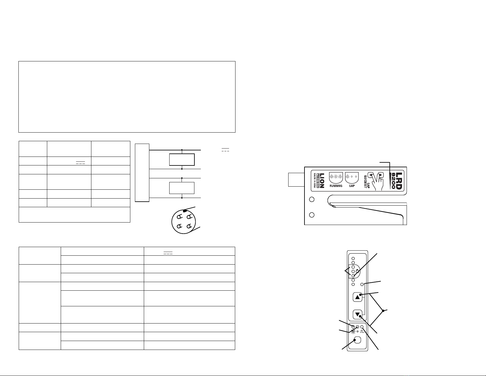
Dark Switching
Output Indicator
Outputs
Light Switching
Output Indicator
Outputs
1s1s
Fig. 3
0.825
21.0
1.575
40.0
0.118
3.0
3.620
91.9
inch
mm
2.0
50.8
0.906
23.0
0.169
4.3
0.354
9.0
Ø
2.600
66.0
0.197
5.0
0.65
16.5 Sensor
0.551
14.0
2X
4.95
125.7
2.0
50.8
inch
mm
0.125
3.18
0.20
5.1
1.25
31.8
0.225
5.72
0.60
15.2
0.80
20.3
4X M4 x 0.7
Contact Commercial Secteur OUEST :
frederic.piteux@alcyonelectronique.fr
Direct : +33 (0)134 947 710 - Mob : +33 (0) 622 920 278
Contact Commercial Secteur EST :
didier[email protected]
Direct : +33 (0)134 947 711 - Mob : +33 (0) 680 923 780
RD 11 – BP20 – 78650 Beynes – France
Tel : +33 (0) 134 947 700 - Fax : +33 (0) 134 875 340
www.alcyonelectronique.fr
Description
The Lion Precision LRD8200 Label Sensor uses ultrasonic technology to monitor label registration
and/or count labels. A change in the sensor output indicates the presence of a label edge.
Connecting to the Sensor
Warnings:
Sensors must not be attached to voltages in excess of 30 VRMS or 60 VDC
All external connections must be SELV (Safety Extra Low Voltage). A shielded cable is required for
full protection and safety compliance.
All power must be off when installing the sensor.
Use of the equipment in any other manner may impair the safety and EMI protections of the
equipment.
If outputs are overloaded, all indicators on the sensor will flash together and sensor will stop
operating. Normal operation will be restored when the overload is removed.
Wire
Color
Connection Notes
1 (Brown) Vin (12-24 V ) 50 mA max.
2 (White) NPN Output 150 mA max.
3 (Blue) Ground Connected to
sensor body
4 (Black) PNP Output 150 mA max.
Shield Ground Sensor Case
Any other wires in the cable (if using 5 wire) are
not connected in the sensor and can be ignored.
Specifications
Power supply Voltage 12-24 V (reverse polarity protected)
Current 50 mA
Response time On or Off 125-425 µs max
Switching Frequency 1 kHz max, 250 m/min for 2mm gaps
Output
Output Current (sinking or sourcing) 150 mA max (overload protected)
Switching output PNP (sourcing) or NPN (sinking),
Dark or light switching
Registration Accuracy 60 m/min: 0.15 mm (0.006")
250 m/min: 0.60 mm (0.024")
Temperature Operating Range 40°F to 140°F (4°C to 60°C)
Protections Supply Inverse Polarity Protection
Switching output Short Circuit and Overload Protection
Sensor Setup
1. Labels must pass under the “Sensing Area” indicator (see fig. 1).
2. Place a gap in the sensor (or remove a label and place the liner only in the sensor)
3. Press both Adjust buttons at the same time to quicly set the sensor, or…
a. Manually use Adjust buttons to light the “Gap Setup” light on the light bar (see fig. 1, 2).
4. Run labels through the sensor to verify that the three “Running” lights (see fig. 1, 2) are active
(on or flashing) while labels are passing through the sensor. If not, use Adjust buttons until
they are. More lights than the three “Running” lights may be active while running labels.
5. If sensor is not performing satisfactorily, adjust up and/or down a few clicks and see if
performance improves, but always keep the three Triple-Check lights on when running.
For best performance, web must remain in contact with the base plate.
Light/Dark Switching
Light/Dark switching mode (see Fig. 3) is displayed by the Light/Dark Indicators (see fig. 2).
To change between light and dark switching, hold the Light/Dark Select (“1S”) button for 1 second.
1 (Brown) +12 to 24
NPN Output
150 mA max.
PNP Output
150 mA max.
Ground
2 (White)
3 (Blue)
NPN Load
PNP Load
4 (Black)
M12 connector on rear of sensor
21
4
3
Sensing Area Indicator
Fig. 1
1s
LIGHT/DARK INDICATORS
Light Switching
Dark Switching
LIGHT BAR &
Triple-Check Verification
Running Lights
While running, these three
lights (or more) are active (on or flashing)
when properly adjusted
OUTPUT INDICATOR
Light is on when outputs are on/conductin
g
LIGHT/DARK SELECT
Changes between light/dark switching
Must be held for one second to change.
UP ADJUST
Shifts light bar up
Hold down for rapid adjustment
GAP QUICKSET
Press both adjust buttons to
quickly set the gap level
DOWN ADJUST
Shifts light bar down
Hold down for rapid adjustment
ADJUST ACKNOWLEDGE
Light flashes green with
every ADJUST key press.
Flashes red when adjustment
is at maximum.
GAP SETUP LIGHT
Adjust to be on when gap
(or liner only) is in sensor
Fig. 2
Other Lion Precision Accessories manuals

Lion Precision
Lion Precision LRD2100 User manual

Lion Precision
Lion Precision LRD2100 User manual

Lion Precision
Lion Precision LRD6110 User manual

Lion Precision
Lion Precision LRD8200 User manual

Lion Precision
Lion Precision LRD 5100 User manual

Lion Precision
Lion Precision LRD5100 Tear-Tape User manual

Lion Precision
Lion Precision LIONEYE 2 User manual

Lion Precision
Lion Precision LRD6300 User manual

Lion Precision
Lion Precision LRD6110 User manual

Lion Precision
Lion Precision LRD6300 User manual


