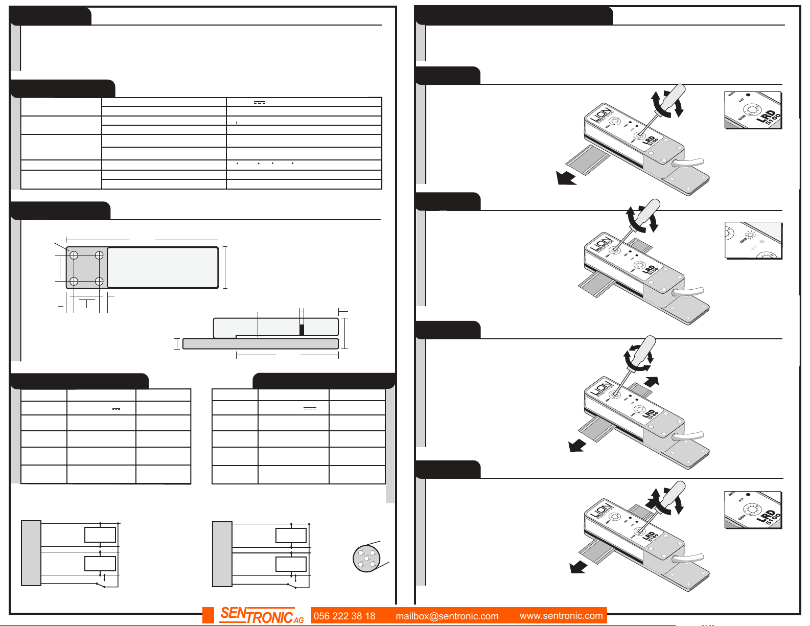
Lion Precision LRD 5100 User manual

This manual suits for next models
1
Other Lion Precision Accessories manuals

Lion Precision
Lion Precision CPL350 User manual

Lion Precision
Lion Precision LRD2100 User manual

Lion Precision
Lion Precision Elite Series User manual

Lion Precision
Lion Precision LIONEYE 2 User manual

Lion Precision
Lion Precision LRD5100 Tear-Tape User manual

Lion Precision
Lion Precision ECL202 User manual

Lion Precision
Lion Precision LRD6110 User manual

Lion Precision
Lion Precision LRD8200 User manual

Lion Precision
Lion Precision LRD6300 User manual

Lion Precision
Lion Precision LRD6300 User manual


Popular Accessories manuals by other brands

Tascam
Tascam US-1x2 Reference manual

Elemental Machines
Elemental Machines Element-B user manual

Waeco
Waeco CoolFun CK40D Hybrid instruction manual

Emerson
Emerson Micro Motion F Series installation manual

Rice Lake
Rice Lake MSI-8000HD Technical manual

National Instruments
National Instruments PXIe-4844 manual


SICK
SICK MRS6000 operating instructions

turck
turck FCS-G3/4A4-NAEX0 manual

Campbell
Campbell CS120A instruction manual

PCB Piezotronics
PCB Piezotronics IMI SENSORS M640B12 Installation and operating manual

BRINKS
BRINKS 7120 Series STEP EASY INSTALLATION INSTRUCTIONS

Clear Comfort
Clear Comfort CCW50 Installation, operation & maintenance manual