Lion Precision LRD2100 User manual

Output and Mechanical Detail
Light/Dark switching is affected by the direction of label movement and the Output Polarity
connection. Output descriptions below are for web direction indicated in the illustration and are
reversed for web movement in the other direction.
Specifications
Power supply Voltage 11-28 V (reverse polarity protected)
Current 50mA
Response time on or off 20µs max
Switching Frequency 10kHz max
Output
Output Current (sinking or sourcing) 150mA max (overload protected)
Switching output PNP (sourcing) or NPN (sinking),
Dark or light switching
Temperature Operating Range 40°F to 140°F (4°C to 60°C)
Protections Supply Inverse Polarity Protection
Switching output Short Circuit and Overload Protection
Two-Year Warranty details at: www.lionprecision.com/warranty.html
User’s Guide
for the
LRD2100 and LRD2100C Label Sensors
from
Lion Precision
SENSOR
5.50"
140mm
3.50"
89mm
Throat Depth
1.00"
25.4mm
Gap 0.03"
0.76mm
(Adjustable)
1.20"
30.5mm
0.60"
15.2mm
0.20"
5.1mm 0.60"
15.2mm
M4x.7
(x4)
*Some models label this indicator as “Edge”
Light Switching
Output Polarity = +V
Dark Switching
Output Polarity = GND Output Indicator*
Outputs
Output Indicator*
Outputs
Web Movement
Direction
Lion Precision
St. Paul, MN, USA
651-484-6544
www.lionprecision.com
Document Number: M014-4660.026
Contact Commercial Secteur OUEST :
Direct : +33 (0)134 947 710 - Mob : +33 (0) 622 920 278
Contact Commercial Secteur EST :
didier.simon@alcyonelectronique.fr
Direct : +33 (0)134 947 711 - Mob : +33 (0) 680 923 780
RD 11 – BP20 – 78650 Beynes – France
Tel : +33 (0) 134 947 700 - Fax : +33 (0) 134 875 340
www.alcyonelectronique.fr
Warnings:
Sensor body is connected to Ground.
Sensors must not be attached to voltages in excess of 30VRMS or 60VDC
All power must be off when installing the sensor.
Use of the equipment in any other manner may impair the safety and EMI protections of the
equipment.
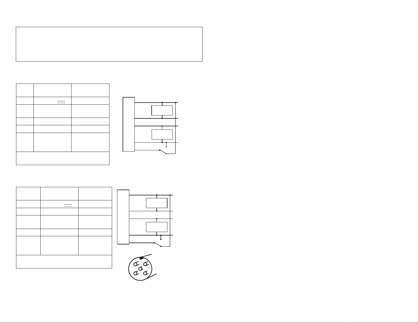
LRD2100 Wiring
Wire
Color
Connection Notes
Red Vin (11-28V ) 50mA max.
Black Ground Connected to
sensor body
Green NPN Output 150mA max.
Blue PNP Output 150mA max.
Brown Output Polarity
(light/dark
switching)
+V or Ground
See detail on
back
Warning: Brown wire must be connected to +V
or Ground for reliable operation.
LRD2100C Wiring
Wire
Color
Connection Notes
1 (Brown) Vin (11-28V ) 50mA max.
2 (White) NPN Output 150mA max.
3 (Blue) Ground Connected to
sensor body
4 (Black) PNP Output 150mA max.
5 (Gray) Output Polarity
(light/dark
switching)
+V or Ground
See detail on
back
Warning: Gray wire (pin 5) must be connected to
Vin or Ground for reliable operation.
See www.labelsensors.com for helpful information.
Adjusting the LRD2100
The adjustments on the LRD2100 have a maximum of four (4) turns. If they are turned beyond the
end points, the adjustments will continue to turn without damaging the sensor, but no further
adjustment will occur.
Adjustments When First Installed On A Machine
1. Remove all material from sensor.
2. Set GAIN ADJUST to maximum by turning at least four (4) turns clockwise.
3. Set ZERO ADJUST
Turn the Zero adjustment to where the Zero light changes between On and Off. It’s not
important whether it is On or Off when completed, as long as it is close to where it changes.
4. It is recommended that you place a round black label (several are included with the sensor)
over the Zero adjustment to prevent unnecessary adjustment in the future.
5. Set GAIN ADJUST to midpoint by turning two (2) turns counterclockwise
This setup will work with most labels and not require readjustment. The Zero may have to be
adjusted again if the baseplate or spacer is ever replaced or removed.
Adjustments When Label Stock Is Changed
Usually None. The basic setting above (Gain at center of its range) will work for most labels.
Very small labels may require an increase in Gain.
If, and ONLY if, the new labels aren't being detected correctly, use this procedure:
1. Re-Set the Gain to center of its range
a. Turn the Gain adjustment at least 4 full turns clockwise
b. Turn the Gain adjustment 2 turns counterclockwise
Run and see if the sensor works correctly. If it does, the Gain had been adjusted and needed to be
re-centered.
If it still does not work correctly, then use this procedure to fine-tune the Gain setting
1. Set Gain to Minimum by turning it 4 turns counterclockwise
2. Move labels through the sensor and increase GAIN (turn clockwise) until the OUTPUT light
("EDGE" on older models) just begins to flash.
If possible, it may be easier to create some slack in the web and just move one gap back-and-
forth through the sensor while adjusting.
3. Turn the Gain adjustment another half-turn clockwise.
4. If the sensor still doesn't detect labels reliably, you may have label materials that require an
LRD6110 or LRD8200.
Lights During Operation:
The OUTPUT light (EDGE on older models) indicates the sensor output. It will be in one state (on or
off) during the label and the other state during the gap depending on the direction of the label
movement and the connection of the Polarity Invert wire (see next page for details).
The Zero light is for first-time setup only and is meaningless during operation.
Notes:
1) For best results, web should ride against sensor baseplate, not “float” in the gap.
Red +11 to 28VDC
NPN Output
150mA max.
PNP Output
150mA max.
Ground
Polarity Invert
Green
Black
Brown
NPN Load
PNP Load
Blue
21
43 5
Connector on rear of sensor
1 (Brown) +11 to 28VDC
NPN Output
150mA max.
PNP Output
150mA max.
Ground
Polarity Invert
2 (White)
3 (Blue)
5 (Gray)
NPN Load
PNP Load
4 (Black)
This manual suits for next models
1
Other Lion Precision Accessories manuals

Lion Precision
Lion Precision LRD6110 User manual

Lion Precision
Lion Precision LRD5100 Tear-Tape User manual

Lion Precision
Lion Precision Elite Series User manual

Lion Precision
Lion Precision LRD8200 User manual

Lion Precision
Lion Precision LIONEYE 2 User manual

Lion Precision
Lion Precision LRD 5100 User manual

Lion Precision
Lion Precision CPL350 User manual

Lion Precision
Lion Precision LRD6110 User manual

Lion Precision
Lion Precision LRD6300 User manual

Lion Precision
Lion Precision LRD6300 User manual


