Rev: 06.15.22 Page 2 CCD-0005474
Introduction
For up-to-date instructions on the assembly of the Lippert
Skyline eBike, in-depth instructions on operating the bike
and navigating the Lippert eBike app, and complete safety
information, please use the link below or the QR code to
navigate to the Owner's Manual.
Introduction ............................................................................... 2
Resources Required ................................................................ 3
Preparation ................................................................................. 3
Installation .................................................................................. 4
Operation ................................................................................... 10
App Information ..................................................................... 11
https://support.lci1.com/convenience-and-leisure/
Lippert eBike
SKYLINE
2. Remove battery keys
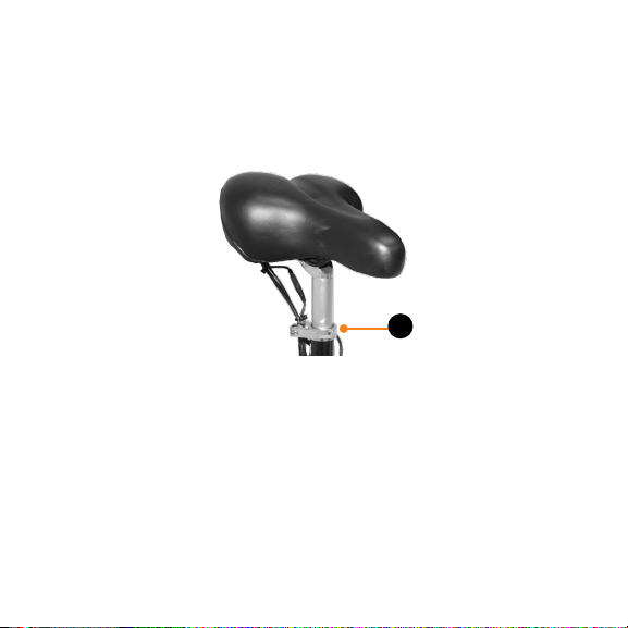
around seat post (Fig. 2).