Look 795 LIGHT RS User manual

MA
NUAL

FR NOTICE D’INSTRUCTIONS 4 - 20
EN MOUNTING INSTRUCTIONS 21 - 37
IT ISTRUZIONI DI MONTAGGIO 38 - 54
ES MANUAL DE MONTAJE 55 - 71
NL MONTAGE HANDLEIDING 72 - 88
D MONTAGEANLEITUNG 89 - 105

5
FR
Félicitations !
Vous avez porté votre choix sur le LOOK 795.
Nous vous remercions de votre confiance
en nos produits.
En choisissant ce nouvel ensemble LOOK,
vous bénéficiez d’un produit de haute
technologie, de conception française.
Votre cadre et ses périphériques sont
identiques à ceux fournis aux grandes
équipes professionnelles, sont contrôlés
durant toute leur fabrication et vous
apporteront entière satisfaction.
Nos produits sont conformes aux différentes
normes européennes et internationales en
vigueur.
Les produits LOOK sont protégés par les
droits de la propriété industrielle.
Pour plus d’information, rendez-vous sur
www.lookcycle.com/patents
PRÉSENTATION DU PRODUIT
Votre ensemble 795 a été développé et
conçu suivant les spécifications du bureau
d’études LOOK afin d’offrir la meilleure
transmission de l’effort et une précision de
pilotage inégalée.
Ces deux caractéristiques sont possibles
grâce à l’intégration de composants
spécifiquement dessinés pour ce cadre. Ils
sont ainsi parfaitement compatibles entre
eux, permettant d’obtenir une meilleure
cohérence de l’ensemble pour plus de
performance.
Ainsi, le 795 intégre plusieurs innovations
mondiales : la potence Aerostem inclinable,
le pédalier ZED 2 100% carbone monobloc,
la fourche HSC 8 100% carbone (avec étriers
de freins intégrés sur le modèle Aerolight),
ainsi que la tige de selle E-Post 2.
Nous vous conseillons pour le montage
des accessoires de vous adresser à un
détaillant agréé LOOK.
Avant toute utilisation, lisez l’intégralité
des instructions, respectez les conseils
donnés afin de profiter pleinement des
atouts de ce produit de haute qualité.
LOOK se réserve la possibilité de
changer les spécifications du produit
et sans avis préalable dans le but de
l’améliorer.
Attention :
Ce cadre LOOK est conçu et optimisé pour
être utilisé par des cyclistes ne dépassant
pas 100 KG (220,5 lbs)
FR
4
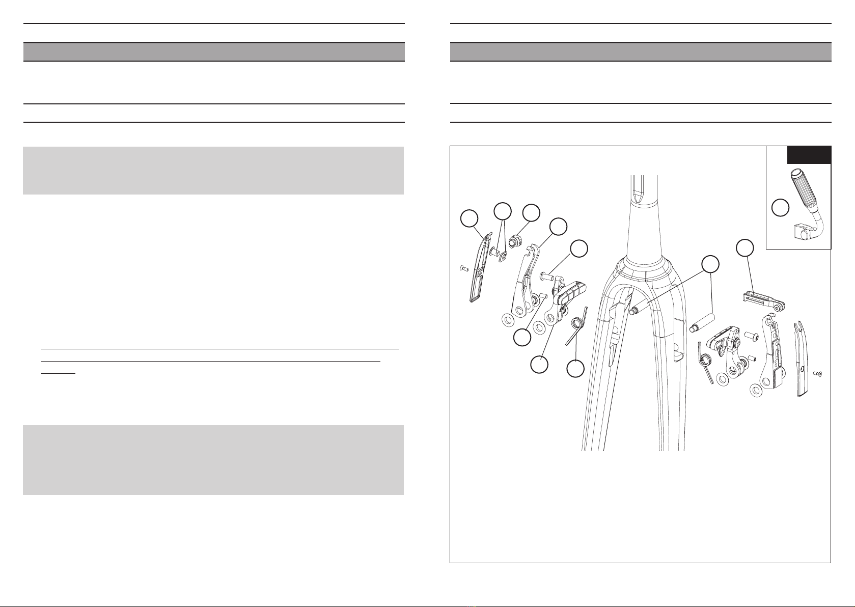
Votre cadre est maintenant livré avec:
• sa fourche et son jeu de direction Head Fit 3 pré-réglé d’usine
• le routage des gaines de frein et de dérailleur pour le montage d’un groupe mécanique.
• sur le modèle Aerolight : les étriers de freins avant sur la fourche et arrière sur le cadre.
Si toutefois vous deviez démonter et remonter ces divers éléments, pour leur entretien par
exemple, voici comment procéder :
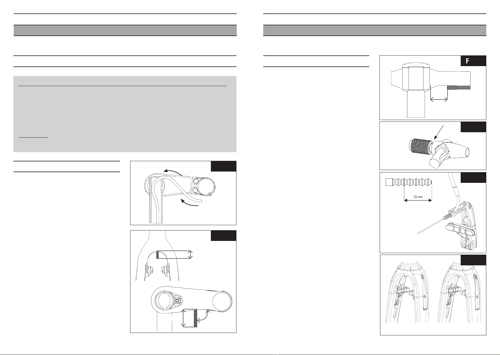
Ordre du montage des gaines :
Routage 795 Light et Aerolight
Mécanique DI2
Dérailleur AR
A passer APRES la mise en place
des portées de roulement dans le
cadre et le montage de la fourche
A passer PENDANT le montage du
jeu de direction
Dérailleur AV
Frein AR
A passer APRES la mise en place
des portées de roulement dans le
cadre et le montage de la fourche
Frein AV A passer APRÈS le montage de la fourche
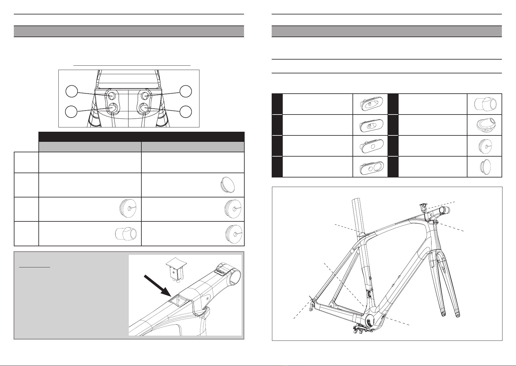
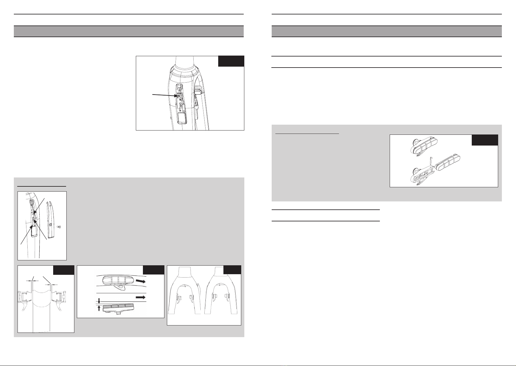
Routage face avant douille:
4 trous sont présents sur la face avant de la douille. Ces 4 trous servent au passage des liners,
gaine de frein arrière, gaines de dérailleur mécanique et électrique. Le tableau ci-après résume
les différentes configurations possibles en fonction du routage (mécanique ou électrique).
Pour une explication complète sur la manière de passer les câbles mécaniques et électriques,
veuillez consulter :
http://www.lookcycle.com/media/upload/795/795.pdf
Pour le montage de la tige de selle E-Post 2,
de la potence Aerostem et du pédalier
ZED 2, merci de vous reporter aux notices
spécifiques à ces produits.
Le 795 n’est pas compatible Campagnolo EPS
Vérification avant installation :
ROUTAGE COMPLET DU 795

7
FRFR
6
1 2
3 4
Routage 795 Aerolight et Light
Mécanique DI2
1Gaine dérailleur AR (
Ø
4mm) Gaine frein AR (
Ø
5mm)
2Gaine frein AR (
Ø
5mm) Bouchon H (trou
Ø
6mm)
3Bouchon G (trou
Ø
7,5mm) Fil dérailleur AR/AV (
Ø
2mm) +
bouchon G (trou
Ø
7,5mm)
4Gaine dérailleur AV (
Ø
4mm) +
Liner + Butée E
Fil dérailleur AR/AV (
Ø
2mm) +
bouchon G (trou
Ø
7,5mm)
BUTÉE DE GAINE AMOVIBLE
Le 795 est équipé de butées de gaines amovibles et de pièces servant au montage du groupe mécanique
ou du groupe Shimano DI2.
795 Light / Aerolight DI2 : type D + F
795 Light / Aerolight méca : type A
795 Light : type B
795 Aerolight : pas de trou
Voir tableau
routage face
avant douille
Accès recharge
batterie ( version DI2)
795 Light : type C
795 Aerolight : type B
AButée amovible mécanique EButée gaine dérailleur
BPasse gaine amovible FBouchon Di2 sortie angle
(fourni par Shimano)
CBouchon butée amovible GBouchon Di2 sortie directe
DPasse fil Di2 amovible HBouchon diamètre 6mm
795 Light / Aerolight DI2 : type G
795 Light / Aerolight méca : rien
ATTENTION :
Ce logement est prévu exclusivement pour
le connecteur Shimano lors d’un montage en
groupe électrique Di2. Lors d’un montage en
mécanique cet emplacement doit rester vide
et fermé. N’y introduisez pas de nourriture,
d’outils ou quel qu’autre objet qui risque
de tomber dans le cadre et d’endommager
sérieusement le fonctionnement du vélo.
VUE FACE AVANT DOUILLE DE DIRECTION :

FRFR
98
INSTALLATION DU JEU DE DIRECTION INTÉGRÉ LOOK 1”1/2
Particularité du jeu de direction:
Le jeu de direction Look Head Fit 3 est
un système breveté apportant plusieurs
améliorations.
Il permet une dissociation du réglage
du jeu de direction avec le réglage de la
potence. Ces deux fonctions deviennent
indépendantes, ce qui permet un réglage
plus simple de la potence et une meilleure
précision dans l’ajustement du jeu de
direction.
De plus, cela augmente la durée de vie des
roulements du jeu de direction lorsque
des efforts importants sont appliqués sur
le cintre.
VUE ÉCLATÉE
Portée de
roulement
droite
Cône de compression
Goupille (x1) et
bouchons (x2)
Portée de
roulement
gauche
Bague de serrage
DOUILLE DE DIRECTION
Roulement 1”1/2
Roulement 1”1/8
Filet rapporté
Attention! L’embout de la vis de tension est aplati de manière à éviter le désengagement du ressort de
maintien lors du desserrage. Veillez à ne pas forcer lors du desserrage sous peine de désengagement
du ressort de tension et de détérioration des filets de ce dernier ou de la vis de tension. Le maintien
de la butée ou son désengagement peuvent s’en trouver affectés.
Démontage
1/ Retirer la gaine éventuellement logée dans la
butée de gaine.
2/ Desserrer la vis de tension jusqu’à
désolidarisation de la butée de gaine.
3/ Extraire la butée. Si la butée oppose une
résistance au retrait, desserrer d’avantage la
vis de tension.
Butée en position
dans son logement
Fig. b
Fig. a
Montage
1/ S’assurer que la butée de gaine est en
position ouverte.
2/ Positionner la butée dans son logement, contre
la paroi en composite du cadre.
3/ Serrer la vis de tension à 1Nm jusqu’au
maintien complet de la butée dans son
logement (Fig. b).
Attention ! Un serrage excessif de la vis de
tension peut conduire à la détérioration des
filets de la vis ou du ressort de maintien. Le
maintien de la butée ou son désengagement
peuvent s’en trouver affectés.
Ressort de
maintien
Cadre
Vis de tension Corps de butée
de gaine
Outil montage/démontage
Utilisezexclusivementl’outildemontage/démontage
prévu à cet effet et livré avec le kit accastillage.
!
BUTÉE DE GAINE AMOVIBLE (TYPE A / B / C / D)

FRFR
1110
NOTA :
Le réglage de la hauteur de la potence étant dissocié du serrage du jeu de direction et le montage
de la fourche avec son jeu de direction nécessitant des outils spécifiques, il est fortement conseillé
de s’adresser à un détaillant agrée LOOK pour effectuer un démontage ou un remontage correct et
complet de la fourche.
Pour toutes opérations de maintenance, nous rappelons que la fourche doit être posée sur une roue
et une usure anormale des pattes qui serait due à une abrasion sur le sol ne peut pas être couverte
par la garantie LOOK.
Attention : Les fourches sont livrées montées sur les cadres avec un pivot d’une longueur spécifique
à chaque taille de douille. Vous n’avez pas à recouper le pivot de fourche de votre 795 pour atteindre
vos réglages. L’ensemble a été conçu pour que seul le réglage de la potence soit suffisant.
REGLAGE DU JEU DE DIRECTION HEAD FIT 3
Attention : Le jeu de direction est monté en usine et réglé de façon à être fonctionnel dès la première
utilisation sans démontage préalable.
Cependant LOOK laisse la possibilité à chaque utilisateur souhaitant durcir ou adoucir leur direction,
de régler très finement la compression des roulements en venant visser ou dévisser la bague de
serrage comme le montre les figures ci dessous, en ayant pris soin d’appliquer du frein filet faible
résistance (type Loctite 222) sur la bague de serrage :
Commencer par engager manuellement la bague
de serrage sur le filet rapporté et ce jusqu’au
contact de cette dernière avec le cône de
compression du roulement supérieur.
Puis pour un serrage plus important, utiliser la clé
fil préconisée par LOOK.
Régler soigneusement le jeu de direction afin qu’il
ne subsiste aucun jeu et que la fourche puisse
tourner librement et sans point dur.
Attention à ne pas serrer la bague de serrage
jusqu’au blocage de la direction ce qui pourrait
à terme endommager prématurément les
roulements et par conséquent le fonctionnement
global de la direction.
Pour le serrage du jeu
de direction, visser la
réhausse sur le filet apporté
Utiliser une clé préconi-
sée pour un serrage et un
deserrage important.
Fig. d
Votre cadre est livré avec une fourche HSC 8 prémontée avec son jeu de direction Head Fit 3 LOOK.
La bague de serrage permettant la mise en compression des roulements a été ajustée en usine pour
permettre un fonctionnement et une précision optimaux dès la première utilisation.
En cas de réglage du jeu de direction, veuillez suivre les conseils du paragraphe « réglage du jeu de direction ».
En cas de démontage du jeu de direction, veuillez suivre les conseils du paragraphe « démontage du jeu de direction ».
En cas de remontage du jeu de direction, veuillez suivre les conseils du paragraphe « remontage du jeu de direction ».
INSTALLATION DE LA FOURCHE HSC 8
Les fourches LOOK comportent une portée d’appui de roulement conique, conçue pour recevoir
directement celui-ci, supprimant ainsi la pose d’un cône de fourche traditionnel.
Elle est conforme à la norme EN 14 781.
Avant toute utilisation, lisez soigneusement l’intégralité des instructions, respecter les conseils donnés
afin de profiter pleinement des atouts de ce produit de haute qualité. LOOK se réserve la possibilité de
changer sans avis préalable les spécifications du produit, dans le but de l’améliorer.
Présentation de la fourche
Fig. c
Collerette conique 36°
Diam. 1’’1/2

FR FR
1312
MONTAGE COMPLET DU JEU DE DIRECTION (suite)
3 / Préparer le sous-ensemble filet rapporté avec le cône
de compression (Fig. f), puis le glisser sur le pivot
de la fourche jusqu’au roulement supérieur. Insérer la
goupille après montage de l’ensemble.
4 / Placer le trou de perçage du filet rapporté en face du
trou de perçage de la fourche, et insérer la goupille au
travers de la douille. S’assurer qu’elle soit bien
centrée, elle ne doit pas dépasser du filet rapporté
pour ne pas gêner le vissage de la bague de serrage.
A ce stade, la fourche avec son jeu de direction et le
cadre ne forment plus qu’un seul sous ensemble. La suite du montage permet de régler
les jeux fonctionnels dans le jeu de direction et de fixer les éléments du poste de pilotage
(élastomère, potence...).
5 / Mettre deux points de frein filet faible (type Loctite 222) sur la bague de serrage
6 / Visser la bague de serrage sur le filet rapporté
et régler le jeu de direction afin qu’il ne
subsiste aucun jeu et que la fourche puisse
tourner librement et sans point dur.
Une fois la bague de serrage serrée, la
goupille est emprisonnée et l’empêche donc
mécaniquement de sortir.
Insérer les deux bouchons en caoutchouc
pour combler les trous de la douille.
A ce stade, la fourche est montée réglée sur le
cadre et le montage des autres éléments
ne peut en aucun cas modifier l’ajustement du
jeu de direction. Il reste donc à monter la
potence à la position désirée.
7 / Procéder au montage de la potence Aerostem
(voir la notice).
Fig. f Perçage goupille
Tube pivot
Potence
Elastomère
DOUILLE
DE DIRECTION
Fig. g
MONTAGE COMPLET DU JEU DE DIRECTION HEAD FIT 3
Le LOOK 795 est livré avec le jeu de direction Head Fit 3.
Attention : Pour le montage complet du jeu de direction Head Fit LOOK, il est fortement
recommander de vous adresser à votre détaillant agréé LOOK.
Description du jeu de direction 1’’1/2 :
Partie inférieure : • Roulement monobloc 36°x 45°, diamètre extérieur 52 mm.
Partie supérieure : • Roulement monobloc 36° x 45°, diamètre extérieur 41mm.
• Cône de compression roulement 1 1/8
• Filet rapporté possédant deux méplats
• Goupille
• Bague de serrage
• Bouchon trou
de goupille
Le jeu de direction intégrant les gaines
pour le routage de votre vélo (en passant
dans les portées de roulements), reportez-
vous au tableau p. 7 pour connaître l’ordre
de montages des gaines de freins et de
dérailleur avant de monter complétement
le jeu de direction.
1 / Placer le roulement supérieur dans les
portées de roulement droite et gauche
puis emmancher l’ensemble dans la
douille supérieure du cadre.
2 / Déposer le roulement inférieur sur
la fourche en prenant soin de placer
le chanfrein inférieur sur le cône de la
fourche.
Elasto continuité potence
(Goupille)
Filet rapporté
Cône de compression
Roulement supérieur
Potence
Bague de serrage
DOUILLE
DE DIRECTION
Roulement
inférieur
Fourche
Fig. e

FR FR
1514
FREINS INTÉGRÉS - VUE ECLATÉE
Fig. h
1 : Capot levier (x2)
2 : Vis et plaque serre câble
3 : Passe câble
4 : Levier extérieur (x2)
5 : Vis réglage approche patin (x2)
6 : Vis tension ressort (x2)
7 : Levier intérieur (x2)
8 : Ressort (x2)
9 : Axe levier
10 : Tirant pour routage interne
10 ‘ : Tirant pour routage externe
1
8
9
10
7
6
5
4
3
2
DEMONTAGE COMPLET DU JEU DE DIRECTION
Attention :
Le démontage complet du jeu de direction LOOK Head Fit 3 nécessite l’utilisation d’outils
spéciaux, il est fortement recommander de vous adresser à votre détaillant agréé LOOK.
1 / Desserrer complètement la potence.
2 / Faire glisser la potence vers le haut du pivot. Enlever les bouchons caoutchouc montés
sur la douille pour cacher les trous de goupille.
3 / Desserrer la bague de serrage à l’aide des outils préconisés (voir Fig. d dans le paragraphe
«réglage du jeu de direction») puis enlever la bague de serrage du pivot de fourche.
Tourner la fourche d’un quart de tour pour aligner la goupille en face des trous de la douille.
4 / Sortir les gaines de routage (qui sont intégrées dans le jeu de direction) des portées de
roulement puis enlever la goupille à l’aide d’un chasse goupille diamètre 4 et la ressortir
de l’autre côté de la douille.
Attention à bien maintenir la fourche pour ne pas qu’elle glisse de la douille et s’abîme
en tombant car une fois la goupille enlevée, aucune butée mécanique ne retient la
fourche.
5 / Enlever le roulement 1’’1/2 inférieur du cône de la fourche.
IMPORTANT :
Ne pas graisser le tube pivot.
Utilisez le jeu de direction Head Fit 3 LOOK fourni avec la fourche HSC 8 ou un jeu de
direction préconisé par LOOK.
10’

FR FR
17
16
Frein avant (Suite)
5 / Le long du cintre, positionner une gaine
depuis le levier de frein, la couper à
30mm de la potence et placer un embout
de gaine (Fig. k).
6 /
Mettre en place le quick-release au bout
de cette gaine en s’assurant qu’il est
bien en position fermée (Fig.l), puis faire
glisser le câble de frein graissé dans
l’ensemble. Faire ensuite glisser le câble
dans la gaine positionnée dans la
potence jusqu’à ce qu’il sorte par l’entre-
branche.
7 / Sortir le tube plastique du coude.
Enfiler le câble dans le tube plastique
et insérer le tout dans le coude.
Remonter le coude jusqu’à ce qu’il soit
en butée contre la gaine.
8 / Engager le coude dans le tirant.
9 / Repousser le coude dans la fourche en
tirant sur la gaine au niveau de la
potence, jusqu’à ce qu’il soit dans sa
position définitive.
10 / Couper le soufflet à 23mm. Le positionner
jusqu’au coude, passer le câble dans le
passe câble et le positionner dans le
levier externe droit (Fig. m).
11 /
Maintenir le câble à l’aide du serre câble
de façon à ce que les deux leviers
externes soient dans la continuité de
la fourche (Fig. n). Il est possible d’affiner
le réglage avec la molette du quick-release.
Fig. k
30 mm
Fig. l
Fig. m
Quick-release :
position fermée
MONTAGE DES FREINS
Montage frein avant (routage interne)
TOUTES LES OPÉRATIONS SUIVANTES SONT À RÉALISER PAR UN DÉTAILLANT AGRÉÉ
Pour le montage des freins, vous aurez besoin des outils suivants :
• jeu de clés Allen
• pince coupante
• embouts de gaine
• embouts de câble
ATTENTION:
Les patins montés d’origine sont uniquement compatibles avec des jantes aluminium.
1 / Monter la gaine dans la potence en la
faisant passer comme indiqué sur la
fig. i.
2 / Positionner la potence sur le pivot de
la fourche et régler la position angulaire
de la potence. Serrer la potence à l’aide
d’une clé Allen 5 mm au couple de 15 Nm
(pour plus d’information, se reporter à la
notice Aerostem).
3 / Faire glisser la gaine dans le pivot de la
fourche jusqu’à l’entre-branche en
laissant dépasser la gaine de 15mm
(Fig. j).
4 / Au niveau de la potence, tendre la gaine
puis la couper à 30mm (Fig. j). Placer un
embout de gaine de frein.
Fig. i
Fig. j
15 mm
30 mm 90°
û
NO ü
OK
Fig. n

FR FR
1918
12 / Une fois cet ajustement réalisé, serrer
le câble à l’aide d’une clé Allen de 3mm
au couple de 6Nm (Fig. o).
13 / Régler le frein (voir ci-dessous)
14 / Couper le câble environ 2 cm après le
serre câble et sertir un embout de câble.
Assurez-vous que l’ensemble se trouve
dans la rainure prévue à cet effet et visser
les capots à l’aide d’une clé Allen de 2mm
au couple de 1Nm.
15/ Actionner le levier une dizaine de fois et
vérifier que les freins fonctionnent bien.
Vérifier aussi le jeu entre les patins et la
jante
Freins Arrière
Le frein arrière est monté directement
d’usine suivant les préconisations du
fabricant. Pour le montage ou le démontage,
veuillez suivre les instructions fournies par
le fabricant du frein.
RÉGLAGE DU FREIN :
Si vous utilisez des jantes larges (> à 24mm) retirer les rondelles entre les
porte-patins et les leviers intérieurs
1. Réglage garde patins (Clé Allen de 3mm, fig. p) : rotation horaire : le
patin s’eloigne de la jante // rotation antihoraire : le patin se rapproche
de la jante
2. Réglage position angle patins (Clé Allen de 4mm, fig. q)
3. Réglage tension de ressort (Clé Allen de 2 mm, fig. r): ajuster la
tension des ressorts afin de symétriser le mouvement des leviers
Angle
d’attaque
du patin :
0,5 mm
Sens de
rotation
de la roue
Fig. q
Montage freins avant (routage externe)
Il est possible de monter votre frein en routage externe, par exemple, lors de votre recherche de
position, pour simplifier un changement de potence.
Après avoir retiré les capots de levier, enlever le tirant pour routage interne, et le remplacer par le
coude pour routage externe livré dans la valisette. Aidez-vous des étapes 5, 6 et 11 à 15 du montage
en interne.
CHANGEMENT DE PATINS
Vérifier que le nouveau patin comporte
l’encoche permettant de bloquer le patin
dans le porte-patin. Ne jamais rouler sans
la goupille.
Retirer les broches à l’aide d’un tournevis
plat, changer les patins en veillant à bien
respecter leur orientation, puis replacer les
broches (Fig. s).
32
1
1,5 // 2 mm Fig. p
û
NO ü
OK
Fig. r
Fig. o
Fig. s

FR
20
MONTAGE DES ROUES
Suivre les indications de montage du fabricant.
Nos pattes de fourche sont conçues avec des
ergots de sécurité.
ENTRETIEN
Nettoyer toujours votre cadre avec du savon ou
détergent léger et de l’eau.
Employer un chiffon doux. Rincer votre cadre à
l’eau et le sécher avec un chiffon.
Ne pas utiliser d’appareil de nettoyage à haute
pression, ni de produits abrasifs.
Pour éliminer les taches de goudron, utiliser un
produit pour carrosserie de voiture.
SERVICE APRÈS-VENTE
Malgré tout le soin apporté à notre fabrication,
si un défaut apparaît ou si une réparation
est nécessaire, s’adresser toujours à votre
revendeur avec la facture d’achat de votre
produit.
GARANTIE
Nos cadres et nos fourches sont garantis cinq
ans à partir de la date d’achat contre tout
vice ou défaut de fabrication. La peinture, la
décoration, le vernis et tout ce qui concerne la
finition sont garantis un an.
Pensez à enregistrer votre garantie sur notre
site www.lookcycle.com
Cette garantie reste limitée à l’acheteur initial
et une preuve d’achat est requise (facture
originale).
La garantie concerne les cadres pour tous vices
ATTENTION :
Inspecter toujours votre vélo avant de
l’utiliser.
Si les tubes de votre cadre LOOK ou votre
fourche ont subi n’importe quel
dommage, rapporter le vélo chez votre
revendeur LOOK pour une inspection.
Prendre connaissance des lois en vigueur
dans le pays où vous êtes. Si vous roulez la
nuit, les réflecteurs ne sont pas suffisants et
ne remplacent pas un éclairage.
Porter toujours un casque
Prendre connaissance du code de la route
et le respecter.
Prendre garde aux dangers de la route et de
la circulation.
ou défauts de fabrication.
La garantie s’applique uniquement si le cadre
est assemblé conformément aux
instructions ci dessus.
La garantie ne s’applique pas aux dégâts
occasionés par un mauvais entretien ou une
mauvaise utilisation.
De même la garantie est caduque si le cadre ou
la fourche a subi une modification technique du
fait de l’utilisateur ou s’il a été réparé, repeint
hors d’un centre de réparation agréé LOOK.
En particulier ne pas supprimer les ergots de
sécurité des pattes de fourche.
La garantie ne couvre pas les cas suivants :
* les dégâts causés par négligence ou entretien
insuffisant
* les accidents
* les dommages accessoires et indirects
Les dépenses de montage, démontage, temps
de main d’oeuvre, emballage et expédition du
cadre ne sont pas couverts.
Ne pas percer, peindre ou revernir.
Ne pas laisser le cadre près d’une source de
chaleur.
Congratulations!
You have chosen the LOOK 795.
We thank you for your trust in our products.
Choosing this new LOOK road bike means
you will enjoy the benefit of a high-tech
product designed in France.
Your frame and its peripheral components
are identical to those supplied to the leading
professional teams, they are inspected
throughout their manufacture and will
ensure you are fully satisfied.
Our products comply with the various
European and International standards in
force.
LOOK products are protected by industrial
property rights.
For further information please visit
www.lookcycle.com/patents
PRODUCT PRESENTATION
Your 795 road bike has been developed and
designed in accordance with LOOK design
department specifications in order to offer
the best power delivery and unrivalled
steering precision.
These two features are made possible
by integrating components designed
specifically for this frame. This means they
are perfectly compatible with one another,
thus achieving improved consistency
throughout for higher performance.
Accordingly, the 795 incorporates several
world firsts: the Aerostem adjustable stem,
ZED 2 one-piece 100% carbon crankset,
HSC 8 100% carbon fork (with integrated
brake callipers on the Aerolight), as well as
the E-Post 2 seatpost.
We would advise you to refer to a
LOOK approved retail outlet for fitting
accessories.
Before any use, read the instructions in
their entirety, observe the advice given
in order to make the most of the features
of this high-quality product.
LOOK reserves the right to change
product specifications and do so without
prior notice with the aim of improving it.
Warning :
This LOOK frame has been designed and
optimised for use by cyclists weighing no
more than 100 kg (220.5 lb)
EN
21
When assembling the E-Post 2 seatpost,
the Aerostem stem and the ZED 2 crankset,
please refer to the specific instructions for
each of these products.
The 795 is not Campagnolo EPS compatible

Your frame is now supplied with:
• its fork and Head Fit 3 headset pre-set in the factory
• brake and derailleur cable sheaths routed for a mechanical groupset.
• on the Aerolight model: the front brake callipers on the fork and rear units on the frame.
Should you nevertheless need to remove and refit these components, e.g. for maintenance,
this is how to do it:
Sheath fitting sequence :
795 Light and Aerolight routing
Mechanical DI2
Rear derailleur
To be fed through AFTER fitting
the bearing seats in the frame and
assembling the fork
To be fed through WHILE assembling
the headset
Front derailleur
Rear brake
To be fed through AFTER fitting
the bearing seats in the frame and
assembling the fork
Front brake To be fed through AFTER assembling the fork
Head tube front face routing:
There are 4 holes on the front face of the head tube. These 4 holes are used to feed through
the liners, rear brake cable sheath, mechanical and electronic derailleur cable sheaths. The
table below summarises the various configurations available according to routing (mechanical
or electronic).
For a full explanation of the method of feeding mechanical and electronic cable sheaths
through, please refer to:
http://www.lookcycle.com/media/upload/795/795.pdf
Pre-installation checklist :
COMPLETE 795 ROUTING
EN EN
1 2
3 4
795 Aerolight and Light routing
Mechanical DI2
1
Rear derailleur cable sheath (Ø4mm)
Rear brake cable sheath (
Ø
5mm)
2
Rear brake cable sheath (Ø5mm)
Plug H (
Ø
6mm hole)
3Plug G (
Ø
7,5mm hole) Rear/front derailleur wire
(Ø 2mm) + Plug G (Ø 7,5mm hole)
4Front derailleur cable sheath
(
Ø
4mm) + Liner + Stop E
Rear/front derailleur wire
(
Ø
2 mm) + Plug G (
Ø
7.5 mm hole)
WARNING :
This recess is provided solely for the
Shimano connector when a Di2 electronic
groupset is fitted. With a mechanical
groupset this recess must be kept empty
and sealed. Do not put food, tools or any
other object in it as it might drop into the
frame and seriously impair the bike’s
performance.
HEAD TUBE FRONT FACE VIEW :
22 23

REMOVABLE SHEATH STOP
The 795 features removable sheath stops and parts for fitting the mechanical groupset or the Shimano
Di2 groupset.
795 Light / Aerolight DI2 : type D + F
795 Light / Aerolight méca : type A
795 Light : type B
795 Aerolight : no hole
See head tube
front face
routing table
Battery charger
aperture (Di2 version)
795 Light : type C
795 Aerolight : type B
A
Mechanical removable stop
EDerailleur cable sheath
stop
BRemovable cable sheath
grommet FDi2 angled exit plug
(supplied by Shimano)
CRemovable stop plug GDi2 direct exit plug
DDi2 removable wire
grommet H6 mm diameter plug
795 Light / Aerolight DI2 : type G
795 Light / Aerolight mech. : none
Warning ! The tip of the tensioning screw is flattened in order to prevent the retaining spring from
disengaging while unscrewing. Take care not to apply excessive force when unscrewing, otherwise
the tensioning spring could disengage and its threads or those of the tensioning screw could strip.
This could affect stop retention or disengagement.
Removal
1/ Withdraw the sheath if it is in place in the
sheath stop.
2/ Loosen the tensioning screw until the stop is
released from the sheath.
3/ Extract the stop. If the stop resists withdrawal,
loosen the screw some more.
Stop in position in
its housing
Fig. b
Fig. a
Fitting
1/ Ensure the sheath stop is in the open position.
2/ Position the stop in its housing, up against the
composite frame wall.
3/ Tighten the tensioning screw to 1 Nm until
the stop is completely secure in its housing
(Fig. b).
Warning ! Tightening the tensioning screw
excessively can result in stripped screw
threads or a damaged retaining spring. This
could affect stop retention or disengagement.
Retaining
spring
Frame
Tensioning screw Sheath stop
body
Fitting / removal tool
Do not use any fitting / removal tool other than the one
provided for the purpose and included in the fittings kit.
!
REMOVABLE SHEATH STOP (TYPE A / B / C / D)
EN EN
24 25

LOOK 1½” INTEGRATED HEADSET INSTALLATION
Headset specific feature:
The Look Head Fit 3 headset is a patented
system boasting several improvements.
It enables headset adjustment to be
dissociated from stem adjustment. This
makes these two functions independent,
which simplifies stem adjustment and
improves precision when adjusting the
headset.
What’s more, this also increases bearing
and headset service life when high loads
are applied to the handlebar.
EXPLODED VIEW
Right-hand
bearing seat
Compression cone
Pin (x1) and
plugs (x2)
Left-hand
bearing seat
Locking ring
HEAD TUBE
1½” bearing
11/8” bearing
Threaded insert
Your frame is supplied with an HSC 8 fork pre-assembled with a LOOK Head Fit 3 headset. The clamping
ring that compresses the bearings has been factory-set to provide optimum operation and precision as
from first use.
If headset adjustment is required, please follow the advice in the “headset adjustment” section.
If the headset needs to be disassembled, please follow the advice in the “headset disassembly” section.
If the headset needs to be re-assembled, please follow the advice in the “headset re-assembly” section
.
HSC 8 FORK INSTALLATION
LOOK forks include a tapered bearing seat designed to take it directly, thus eliminating the need to fit a
traditional fork cone.
It complies with standard EN 14 781.
Before any use, read the instructions carefully in their entirety, observe the advice given in order
to make the most of the features of this high-quality product. LOOK reserves the right to change the
specifications of the product without prior notice, with the aim of improving it.
Fork presentation
Fig. c
36° tapered collar
1½’’ dia.
EN EN
26 27

NOTE:
Since adjusting stem height has been dissociated from tightening the headset and assembling the fork
to its headset requires dedicated tools, it is highly advisable to go to an LOOK approved retail outlet to
have the fork disassembled and reassembled correctly and completely.
For any maintenance work, we would remind you that the fork must be fitted to a wheel and that abnor-
mal wear of the dropouts caused by abrasion on the ground cannot be covered by LOOK’s warranty.
Warning: Forks are supplied fitted to the frames with a specific steerer length for each size of head
tube. You don’t need to cut down the steerer tube on your 795 to achieve your settings. The assembly
has been designed so that simply adjusting the stem is sufficient.
HEAD FIT 3 HEADSET ADJUSTMENT
Warning: The headset is assembled in the factory and adjusted so it is functional as from first use
without the need for prior disassembly.
Nevertheless LOOK still leaves it open to each user wishing to stiffen or lighten their steering, to make
very fine adjustments to the preload on the bearings by screwing down or unscrewing the clamping
ring as shown in the illustrations below, having taken care to apply low-strength threadlocker (such
as Loctite 222) on the clamping ring:
Start by engaging the clamping ring manually
into the threaded insert until the latter comes into
contact with the top bearing compression cone.
Then use the wire spanner recommended by
LOOK for more substantial tightening.
Adjust the headset carefully such that there is no
play remaining and the fork is able to turn freely
without any stiff points.
Take care not to tighten the clamping ring to the
point where the steering locks up which could
in time damage the bearings prematurely and
consequently the steering function as a whole.
To tighten the headset,
screw the spacer onto the
threaded insert
Use a recommended span-
ner for substantial tighte-
ning and loosening.
Fig. d
HEAD FIT 3 HEADSET COMPLETE ASSEMBLY
The LOOK 795 bike is supplied with the Head Fit 3 headset.
Warning: For complete assembly of the LOOK Head Fit headset you are strongly advised to
refer to your LOOK approved retail outlet.
1½’’ headset description :
Lower section : • 36° x 45° one-piece bearing, 52 mm outside diameter.
Top section : • 36° x 45° one-piece bearing, 41 mm outside diameter.
• 11/8” bearing compression cone
• Threaded insert with two flats
• Pin
• Locking ring
• Pin hole plug
As the headset incorporates the sheaths for
your bike’s cable routing (passing through
the bearing seats), please refer to the table
on p. 24 for the brake and derailleur cable
sheath fitting sequences before assembling
the headset completely.
1 / Place the top bearing in the right and left-
hand bearing seats then fit the assembly
into the frame head tube.
2 / Drop the bottom bearing onto the fork
taking care to place the bottom chamfer
on the fork taper.
Stem elastic continuity
(Pin)
Threaded insert
Compression cone
Top bearing
Stem
Locking ring
HEAD TUBE
Bottom
bearing
Fork
Fig. e
EN EN
28 29

HEADSET COMPLETE ASSEMBLY (continued)
3/ Prepare the threaded insert with compression cone
subassembly (Fig. f), then slide it over the fork steerer
up to the top bearing. Insert the pin after assembling
the unit.
4/ Align the drilled hole in the threaded insert with
the drilled hole in the fork and insert the pin
through the steerer. Ensure it is centred correctly,
it must not protrude from the threaded insert
which would impede screwing down the clamping ring.
At this stage, the fork with its headset and the frame
constitute a single subassembly. The next assembly steps
consist of setting functional clearances in the headset and fastening the steering components
(elastomer, stem, etc.).
5/ Apply two dots of low-strength threadlocker (such as Loctite 222) to the clamping ring.
6/ Screw the clamping ring onto the threaded insert and adjust the headset such that there is
no play remaining and the fork is able to turn
freelywithoutanystiffpoints.Oncetheclamping
ring has been tightened, the pin is trapped,
thus providing a mechanical lock to stop it
coming out. Insert the two rubber plugs to
blank off the holes in the head tube.
At this stage the fork is assembled to the frame
and set: on no account can fitting the remaining
components alter headset adjustment. All that
remains is to fit the stem in the desired position.
7/ Fit the Aerostem (see instructions).
Fig. f Pin drilling
Steerer tube
Stem
Elastomer
HEAD TUBE
Fig. g
HEADSET COMPLETE DISASSEMBLY
Warning :
Complete disassembly of the LOOK Head Fit 3 headset requires the use of special tools, you
are therefore strongly advised to refer to your LOOK approved retail outlet.
1/ Loosen the stem completely.
2/ Slide the stem towards the top of the steerer. Remove the rubber plugs fitted to the head
tube to conceal the pin holes.
3/ Unscrew the clamping ring using the recommended tools (see Fig. d in the “headset
adjustment” section) then remove the clamping ring from the steerer tube. Turn the fork a
quarter turn to align the pin with the holes in the head tube.
4/ Withdraw the routing sheaths (which are incorporated in the headset) from the bearing
seats then remove the pin using a 4 mm diameter pin drift and retrieve it from the other side
of the head tube.
Take care to hold the fork securely to prevent it from slipping out of the head tube and
being damaged when it drops since once the pin has been removed there is no mechanical
stop to retain the fork.
5 / Remove the bottom 1½” bearing from the fork taper.
IMPORTANT :
Do not lubricate the steerer tube.
Use the Head Fit 3 LOOK headset supplied with HSC 8 fork or a headset recommended by
LOOK.
EN EN
30 31

INTEGRATED BRAKES – EXPLODED VIEW
Fig. h
1: Arm cap (x2)
2: Screw and cable-clamping plate
3: Cable guide
4: Outside arm (x2)
5: Pad clearance adjustment screw (x2)
6: Spring tension screw (x2)
7: Inside arm (x2)
8: Spring (x2)
9: Arm shaft
10: Yoke for internal routing
10’: Yoke for external routing
1
8
9
10
7
6
5
4
3
210’
BRAKE ASSEMBLY
Front brake assembly (internal routing)
ALL THE FOLLOWING OPERATIONS ARE TO BE CARRIED OUT BY AN APPROVED RETAIL OUTLET
You will need the following tools to assemble the brakes:
• set of Allen keys
• cutting pliers
• sheath ends
• cable ends
WARNING:
The factory fit pads are only compatible with aluminium rims.
1/ Fit the sheath in the stem feeding it
through as shown in Fig. i.
2/ Position the stem on the steerer tube
and set the stem angular position.
Tighten the stem using a 5 mm Allen
key to a torque of 15 Nm (please refer
to the Aerostem instructions for more
information).
3/ Feed the sheath into the steerer tube
down to the fork crown leaving 15 mm of
sheath protruding (Fig. j).
4/ Pull the sheath at the stem end then cut it
off at 30 mm (Fig. j). Fit a brake sheath end.
Fig. i
Fig. j
15 mm
30 mm 90°
EN EN
32 33

Front brake (continued)
5/ Run a sheath along the handlebar from the
brake lever, cut it at 30 mm from the stem
and fit a sheath end (Fig. k).
6/ Fit the quick-release at the end of this
sheath making sure that it is actually in the
closed position (Fig. j), then feed the
lubricated brake cable through the
assembly. Next feed the cable into the
sheath located in the stem until it comes
out at the fork crown.
7/ Withdraw the plastic tube from the elbow.
Thread the cable through the plastic tube
and insert both into the elbow. Reassemble
the elbow to butt up against the sheath.
8/ Engage the elbow in the yoke.
9/ Press the elbow into the fork by pulling
on the sheath at the stem end, until it is in
its permanent position.
10/ Cut the gaiter down to 23 mm. Position it up
to the elbow, feed the cable through the
cable guide and locate it in the right-hand
outside arm (Fig. m).
11/ Hold the cable using the cable clamp
such that the two outside arms are flush
with the fork. (Fig. n). Fine adjustment
can be made using the quick-release
knurled adjuster.
Fig. k
30 mm
Fig. l
Fig. m
Quick-release:
closed position
û
NO ü
OK
Fig. n
12/ Once this adjustment has been completed,
clamp the cable using a 3 mm Allen key to
a torque of 6 Nm (Fig. o).
13/ Adjust the brake (see below).
14/ Cut the cable off about 2 cm after the pinch
bolt and crimp on a cable end. Make sure
the assembly is located in the groove
provided for this purpose and screw on the
caps using a 2 mm Allen key to a torque of
1 Nm.
15/ Operate the lever around ten times and
check the brakes for correct operation.
Alsochecktheclearancebetweenthepads
and the rim.
BRAKE ADJUSTMENT:
If you are using wide rims (> 24 mm) remove the spacers between the pad
holders and the inside arms.
1. Adjusting pad clearance (3 mm Allen key, Fig. p): clockwise rotation:
pad moves away from the rim // anticlockwise rotation: pad moves
closer to the rim.
2. Adjusting pad toe-in (4 mm Allen key, Fig. q)
3. Adjusting spring tension (2 mm Allen key, Fig. r): adjust spring tension
so arms move symmetrically.
Wheel
rotation
direction
Fig. q
Pad toe-in:
0,5 mm
32
1
1,5 // 2 mm Fig. p
û
NO ü
OK
Fig. r
Fig. o
EN EN
34 35

Rear brakes
The rear brake is assembled directly
from the factory in accordance with
the manufacturer’s recommendations.
For assembly or disassembly, follow
the instructions supplied by the brake
manufacturer.
Front brake assembly (external routing)
You can assemble your brake with external routing, for instance when seeking the right
position, to simplify changing the stem.
After having removed the arm caps, remove the internal routing yoke and replace it with the
elbow for external routing supplied in the pack. Follow steps 5, 6 and 11 to 15 for internal routing.
PAD REPLACEMENT
Make sure the new pad includes the notch
to lock the pad in the holder. Never ride
without the pin.
Remove the pins using a flat screwdriver,
replace the pads ensuring their orientation
is correct, then refit the pins (Fig. s).
Fig. s
EN EN
36 37
MOUNTING THE WHEELS
Follow the manufacturer’s mounting instructions.
Our fork tabs are made with safety tabs.
MAINTENANCE
Always clean your frame with soap or a mild
detergent and water.
Use a soft cloth. Rinse your frame with water and dry
it with a cloth.
Do not use high pressure cleaning equipment or
abrasive products.
To eliminate tar, use a car-cleaning product.
AFTER-SALES SERVICE
In spite of the care brought to our manufacturing, if
a defect appears or if repair is necessary, always
contact your wholesaler with the frame or the fork
together with the warranty card.
WARRANTY
We recommend you keep you receipt and register your
guarantee online via the website: www.lookcycle.com
LOOK frames provide the best and latest technology.
However, they do not guarantee safety in the event of
an accident.
LOOK,through itsauthorized distributorsin eachcountry
where the product is sold through retail, guaranties the
initial buyer or user that this product shall be free from
defects in materials and workmanship. This Limited
Warranty is valid for 5 years from the date of purchase
(1 year for paint, decoration, varnish and everything
concerning the finishing).
For warranty claims or service, the product should be
returned to your local authorized LOOK reseller with
this Product Notice and proof of purchase.
This Limited Warranty does not apply to normal wear,
nor to parts that have been refurbished, repaired or
modified, nor to damage caused by accident, abusive
use, poor maintenance or improper use. Improper use
which voids this warranty includes spinning (indoor
exercise), jumping, acrobatic figures, extreme cycling
or similar activities.
The sole remedy under the LOOK Limited Warranty
or any implied warranty shall be limited to the repair
or replacement, at LOOK’s sole option, of the subject
product or parts thereof.
In no event shall LOOK, its agents or distributors, be
liable for damages, direct, indirect or consequential,
nor for any costs of transport or shipping of product,
whether the claim be based on contract, warranty,
negligence, or product liability. As well, they will not
be held responsible for loss or damage to property
other than the warranted product itself, nor for the
loss or damage to other property or other economic
losses. Neither LOOK nor any agent or distributor
shall be liable for contribution or indemnity, whatever
the cause. Warranty rights and remedies may not be
assigned or transferred.
LOOK’s obligations under any warranty shall be limited
to the greatest extent allowed by law as provided
in this LOOK Limited Warranty. Some states do not
allow limitations on how long an implied warranty
lasts and/or the exclusion or limitation of incidental or
consequential damages, so the above limitation and
exclusion may not apply to you.
This Limited Warranty gives you specific legal rights
and you may also have other rights which vary from
state to state.
ATTENTION:
Always inspect your bike before use.
If the tubes of your LOOK frame or your fork were
subject to any damage, bring the bike to your LOOK
retailer for an inspection.
Acquaint yourself with the laws in force in the country
where you are if you ride at night. The reflectors are
not sufficient and do not replace lighting.
Always use a helmet
Acquaint yourself with the Highway Code and
respect it.
Beware of road and traffic dangers.

39
IT
Congratulazioni!
Avete scelto il modello LOOK 795 e vi
ringraziamo della fiducia dimostrata nei
nostri prodotti.
Scegliendo questa nuova bici LOOK,
disporrete di un prodotto tecnologicamente
evoluto, di progettazione francese.
Il vostro telaio e i suoi componenti sono
identici a quelli forniti alle grandi squadre
professionistiche e sono sottoposti a
controlli durante tutte le fasi di produzione
per la Vostra massima soddisfazione.
I nostri prodotti sono conformi alle varie
norme europee ed internazionali vigenti.
I prodotti LOOK sono oggetto di diritti di
proprietà industriale.
Per maggiori informazioni, visitate il sito
www.lookcycle.com/patents
PRESENTAZIONE DEL PRODOTTO
La vostra bici 795 è stata sviluppata e
concepita in base alle specifiche del
Centro Progettazione LOOK per offrire una
trasmissione ottimale dello sforzo e una
precisione di guida senza pari.
Queste due caratteristiche sono possibili
grazie all’integrazione di componenti
espressamente studiati per questo telaio.
Sono perfettamente compatibili tra loro
e consentono di ottenere un insieme più
coerente e prestazioni superiori.
L’attacco manubrio Aerostem inclinabile, la
pedaliera ZED 2 100% carbonio monoblocco,
la forcella HSC 8 100% carbonio (con pinze
freni integrate sul modello Aerolight) e l’asta
reggi-sella E-Post 2.
Per il montaggio degli accessori, si
consiglia di rivolgersi ad un rivenditore
autorizzato LOOK.
Prima dell’utilizzo, leggere
interamente le istruzioni e rispettare le
raccomandazioni fornite per approfittare
appieno dei vantaggi offerti da questo
prodotto di alta qualità.
LOOK si riserva la facoltà di modificare
senza preavviso le specifiche
del prodotto nell’ottica del suo
miglioramento.
Attenzione:
Questo telaio LOOK è stato progettato e
ottimizzato per l’utilizzo da parte di ciclisti
del peso massimo di 100 kg (220,5 lbs)
IT
38
Il telaio viene ora fornito completo di:
• forcella e gruppo sterzo Head Fit 3 preregolato in stabilimento
• il routing delle guaine freni e del cambio di velocità per il montaggio di un gruppo meccanico.
• Modello 795 Aerolight : le pinze freni anteriori sulla forcella e posteriori sul telaio.
Qualora occorra procedere allo smontaggio/rimontaggio di questi vari elementi (ad esempio, in
caso di manutenzione), procedere nel seguente modo:
Ordine di montaggio delle guaine:
Routing 795 Light e Aerolight
Meccanico DI2
Cambio di
velocità post
Da inserire DOPO il montaggio
delle sedi cuscinetti nel telaio e il
montaggio della forcella
Da inserire DURANTE il montaggio
del gruppo sterzo
Cambio di
velocità ant.
Freno post.
Da inserire DOPO il montaggio delle
sedi cuscinetti nel telaio e il mon-
taggio della forcella
Freno ant. Da inserire DOPO il montaggio della forcella
Routing lato anteriore tubo sterzo:
Quattro fori sono presenti sul lato anteriore del tubo sterzo. Essi servono per il passaggio
dei condotti, della guaina freno posteriore e delle guaine cambio di velocità meccanico ed
elettrico. La tabella successiva riassume le varie configurazioni possibili in funzione del routing
(meccanico o elettrico).
Per la spiegazione completa delle modalità di passaggio dei cavi meccanici ed elettrici,
consultare :
http://www.lookcycle.com/media/upload/795/795.pdf
Per il montaggio dell’asta reggi-sella E-Post
2, del braccio manubrio Aerostem e della
pedaliera ZED 2, si prega di fare riferimento
alle relative istruzioni specifiche.
Il modello 795 non è compatibile Campagnolo
EPS
Verifica prima del montaggio:
ROUTING COMPLETO DEL MODELLO 795
Other manuals for 795 LIGHT RS
1
Table of contents
Languages:
Other Look Bicycle manuals