Liquid Controls Avery-Hardoll BM Series User manual

Liquid Controls, LLC
105 Albrecht Drive
Lake Bluff, IL 60044
Tel: +1 847 295-1050
Fax: +1 847 295-8252
www.LCmeter.com
www.AHmeters.com
The information contained herein is the property of Liquid
Controls, LLC. No part may be reproduced or used except as
authorized by contract or other written permission. The Company
reserves the right to alter without notice the specification, design
or conditions of supply of any product or service.
BM series bulkmeter capsule
-with calibrating mechanism and register
Maintenance manual and spare parts list
Publication ref:
TP0003B
February 2016

TP0003B
AMENDMENT RECORD
CHAP/
PAGE DESCRIPTION DATE
AMENDMENT/
ISSUE NO.
Page (iii)/(iv)
TP0003B Ownership change; Regulatory updates 08-Feb-2016

TP0007
Page (iv)

TP0003B
Liquid Controls
It is the aim of Liquid Controls to maintain a policy of continuous progress and for this reason Liquid
Controls reserves the right to modify specifications without notice. This manual provides the information
required to install, service and overhaul the equipment. Although every effort has been made to
ensure absolute accuracy, Liquid Controls does not hold itself responsible for any inaccuracies that
may be found.
PRODUCT SAFETY
In the interest of safety it is strongly recommended by Liquid Controls that the following details receive
strict attention.
For the Purpose of Definition, the word PRODUCT applies to any product sold by Liquid Controls.
1The Product is used only with fluids stated as acceptable by Liquid Controls.
2The Product, while in service, must not be subjected to pressures greater than the Maximum
Working Pressure or tested to pressures greater than the Test Pressure as specified in the manual.
3The Product must only be coupled/connected to equipment considered acceptable by Liquid Controls.
4 The Product must be handled using the lifting handles where fitted, or in accordance with the
manual.
5 The Product must not be misused or handled in any way liable to cause damage.
6 The Product must be inspected for any signs of damage prior to use e.g. cracks, damaged seals,
seized or tight operating mechanisms.
7The Product must be subjected to a regular maintenance program, either in accordance with the
manual or as agreed with Liquid Controls.
8Only technically competent personnel should repair or maintain the Product and only parts supplied
by Liquid Controls may be used.
9Products covered by warranty may not be modified in any way without prior written permission of
Liquid Controls.
10 Products not in service, must be stored in a clean area, and should not be subjected to excessive
temperature, humidity, sunlight, or strong artificial light. Products should be protected to prevent
damage or the ingress of foreign matter.
11 Where applicable, attention should be drawn to dangers resulting from the generation of static
electricity in product flow lines.
12 This equipment is not suitable for use with Liquid Petroleum Gas (L.P.G).
Page (v)/(vi)

TP0007
Page (vi)

TP0003B
WARNINGS
(1) FLUOROCARBON. DO NOT HANDLE O-RINGS/SEALS IF THEIR MATERIAL
APPEARS CHARRED, GUMMY OR STICKY. USE TWEEZERS AND WEAR NEOPRENE
OR PVC GLOVES. DO NOT TOUCH ADJACENT PARTS WITH UNPROTECTED HANDS.
NEUTRALIZE ADJACENT PARTS WITH A SOLUTION OF CALCIUM HYDROXIDE. IF THE
DEGRADED MATERIAL OR ADJACENT PARTS TOUCH THE SKIN, DO NOT WASH OFF
WITH WATER, SEEK IMMEDIATE MEDICAL AID FOR POSSIBLE CONTAMINATION WITH
HYDROFLUORIC ACID. HYDROFLUORIC ACID IN CONTACT WITH SKIN HAS DELAYED
SYMPTOMS OF CONTAMINATION. IT IS EXTREMELY TOXIC.
(2) WORK MUST BE CARRIED OUT ONLY BY SUITABLY QUALIFIED PERSONNEL.
(3) PRIOR TO COMMENCING WORK, ENSURE THAT ALL AIRPORT/COMPANY
SAFETY PROCEDURES HAVE BEEN COMPLIED WITH.
Page (vii)/(viii)

TP0007
Page (viii)

TP0003B
CONTENTS
Preliminary material
Title page
Amendment record
Health and safety at work act and product safety
Warnings
Contents (this page)
Chapters
1 Introduction
2 Technical description
3 Specification
4 Installation, operation and maintenance (WARNING)
5 Servicing (WARNING)
6 Fault finding
7 Spares parts catalogue
8 Rate of Flow indicator
Page (ix)/(x)

TP0007
Page (x)

TP0003B
BM METER
Chap 1
Page 1
INTRODUCTION
Chapter 1
INTRODUCTION
1 GENERAL INFORMATION
1.1 Avery--Hardoll brand bulkmeters are precision made liquid measuring instruments designed for use
with a variety of bulk liquids and maintain accurate metering over long periods of operation. Simplicity
of design and construction together with sustained accuracy has led to wide use of the meters by oil
companies, government departments, and chemical plants around the world.
1.2 The bulkmeter consists of a body casing containing a rotor assembly with four vanes in opposing
pairs, each pair connected by rigid rods. An inlet and outlet manifold is bolted on top of the casing.
FIG 1.1 CAPSULE SIZES
SINGLE DOUBLE TRIPLE
1.3 The basic design of all the series is similar. The higher flow rating for larger meters is achieved by
bolting casings together and fitting them with multiple rotor assemblies respectively with larger
manifolds to suit. See Fig 1.1.
1.4 The series consists of eight meters for pipeline sizes of 2.5 to 6 inches and are of the positive
displacement type as illustrated in Fig 1.2.
1.5 All meters can either be left or right hand discharge and mounted horizontally or vertically.
1.6 The operation of the meter is as follows: Product enters the meter through the inlet side of the
manifold and causes the rotor to revolve by pressure on the vanes. The proximity of the rotor to the
front and rear of the casing forms an efficient seal, whilst the profile of the casing guides the vanes
onto the measuring crescent.
1.7 The manifold and body are constructed separately to avoid pipework stress being transmitted to the
metering crescent.
1.8 The meter is not affected by variations in flow up or downstream.
1.9 Accurate readout is possible because:
•The volume contained within the measuring crescent is highly repeatable.
•The dimensions of the measuring chamber are reasonably insensitive to changes of
temperature.
•The use of pressure balanced end covers minimises pressure induced distortion within
the measuring chamber.
•Meter body materials are chosen for their excellent wear and low frictional properties.

TP0003B
BM METER
Chap 1
Page 2 INTRODUCTION
FIG 1.2 METER OPERATION (RIGHT HAND DISCHARGE SHOWN)
INLET
INNER
COVERS
CASING
VANE
ROTOR
MEASURING
CRESCENT
ROD
S13610
OUTER
COVERS
1.10 The Bulkmeter produces an output on the rotor shaft proportional to flow. The shaft passes through
the end cover without gearing and all moving parts are constantly immersed in fluid.
1.11 There are several ways of using this output:
•A Mechanical Counter driven through a calibrating mechanism to record batch quantity
and totaliser.
•A Pulse Transmitter mounted directly to the output to relay flow to an electronic
counter and display system, such as Masterload.
1.12 Using a Mechanical Counter, display is available in: Litres, Decalitres, Litres x 10, Imperial gallons,
US gallons and Cubic Metres.
1.13 For further information on the Masterload System and other equipment, please refer to Technical
Manuals TP0025 (Vehicle) and TP0027 (Gantry).
1.14 Accessories that may be fitted to the Bulkmeters are:
•Mechanical Counters, (also with integral electronic pulser output).
•Mechanical Ticket Printers.
•Mechanical Preset Counter with mechanical and electrical switch output.
•Mechanical Preset Valves.
•Electrically Operated Preset/Control Valves.
•Pulse Transmitter.
•Extended Counter Drive and Swivel.

TP0003B
BM METER
Chap 1
Page 3
INTRODUCTION
•Temperature Compensator.
•Volume/Weight Convertor.
•Additive Injection Mechanism.
•Strainer.
•Air Separator.
•Flow Governor.
1.15
1.16
1.17
Refer to Chapter 2 for further details on accessories.
Each meter is fully tested and calibrated by Liquid Controls trained staff prior to dispatch and
will, when correctly installed and regularly serviced, maintain a high standard of accuracy and
repeatability.
Each meter is suitable for use in Group II Category 2 for Zone 1 operation.

TP0003B
BM METER
Chap 1
Page 4 INTRODUCTION
Intentionally left blank

TP0003B
BM METER
Chap 2
Page 1
TECHNICAL DESCRIPTION
Chapter 2
TECHNICAL DESCRIPTION
CONTENTS
Para
General Information 1..............................................................................
Manifold 2.........................................................................................
Body Assembly 3..................................................................................
Dynamic Seals 4...................................................................................
Rotor Assembly 5..................................................................................
Calibrating Mechanism 6............................................................................
Mechanical Register 7..............................................................................
Meter Accessories 8................................................................................
Ticket Printer 9....................................................................................
Mechanical Preset Register and Valve 10.............................................................
Rate of Flow Indicator 11............................................................................
Temperature Compensator 12.......................................................................
Additive Mechanism 13.............................................................................
Strainer 14........................................................................................
Volume/Weight Adaptor 15..........................................................................
Air Separator 16...................................................................................
Flow Governor 17.................................................................................
Extended Counter Drive and Swivel 18................................................................
Trolley 19.........................................................................................
Masterload 20.....................................................................................
1 GENERAL INFORMATION
1.1 BM Series Bulkmeters are manufactured in three basic sizes with different ratings identified by a
series number. The series numbers, sizes, flow rates and a brief description of each series of meter
are shown in Table 1.
TABLE 1 - TYPES OF BULKMETER
S
E
R
I
E
S
N
O
MANIFOLD FLOW RANGE
G
E
N
E
R
A
L
D
E
S
C
R
I
P
T
I
O
N
S
ERIE
S
N
O
ins. mm imp. gals. litres
G
ENERAL DE
S
C
RIPTI
O
N
BM250 21/2 63 25 - 250 115 - 1140
S
i
n
g
l
e
c
a
p
s
u
l
e
m
e
t
e
r
s
BM950 376 30 - 300 130 - 1370
S
ingle capsule meters
BM450 376 45 - 450 200 - 2050
BM550 4102 50 - 500 220 - 2280 Double capsule meters
BM350 4102 55 - 550 250 - 2500
p
BM650 4102 65 - 650 300 - 3000
T
r
i
p
l
e
c
a
p
s
u
l
e
m
e
t
e
r
s
BM750 6152 65 - 650 300 - 3000 Triple capsule meters
BM850 6152 85 - 850 387 - 3870 Special application only for low
viscosity/clean aviation fuel
1.2 The BM series bulkmeters consist of three main assemblies, the manifold, body assembly and rotor
assembly, (Figure 2.1). The basic design of all the bulkmeters is similar. The higher rating of the
larger meters is achieved by bolting two or three body casings (capsules) together and fitting double
or triple rotor assemblies with a larger manifold to suit. A calibrating mechanism and Mechanical
Register are also attached to the front end cover. These can be replaced by a front cover
incorporating a pulse transmitter when required for electronic systems, such as Masterload.

TP0003B
BM METER
Chap 2
Page 2 TECHNICAL DESCRIPTION
FIG 2.1 BULKMETER MAIN COMPONENTS
MECHANICAL
REGISTER
DUCTILE IRON MANIFOLD
(SINGLE/DOUBLE CAPSULE ONLY)
ROTOR
ASSEMBLY
OUTER AND INNER COVERS
S13615
FABRICATED STEEL MANIFOLD
(ALL CAPSULES)
CALIBRATING
MECHANISM
2 MANIFOLD
2.1 The manifold is of ductile iron for 2.5” and 3” bores only, or steel fabrication with a bore of either 2.5”,
3”, 4” or 6”, dependant upon the metering capacity (refer to Table 1). The manifold is secured to the
body casing by studs, nuts and washers and sealed by an ’O’ ring seal, the center studs are sealed
with an ’O’ ring seal and fitted washer. Flanges fitted to the manifold can either be flat or raised face.

TP0003B
BM METER
Chap 2
Page 3
TECHNICAL DESCRIPTION
3 BODY ASSEMBLY
3.1 The body assembly comprises a body casing with front and rear double end covers. The body casing
of NI-resist cast iron forms the metering compartment and is machined internally on two concentric
diameters which are joined by blending radii. The larger diameter forms the measuring crescent
(Figure 2.2) and the blending radii are machined out to form the inlet and outlet ports.
3.2 The body casing is fitted with pressure balanced inner end covers, the inner covers are of NI-resist
cast iron while the standard outer covers are of aluminium, NI-resist cast iron is available as an
alternative. The volume between them is fluid filled at line pressure, this ensures that there is no
pressure difference across the inner covers of the measuring chamber and therefore, no distortion.
3.3 A bearing is housed within each inner cover to provide support for the rotor assembly. A bearing
adjuster, screwed into the front inner cover and a compensating spring between the rear bearing and
rear outer cover enables the position of the rotor assembly, within the body, to be adjusted. The front
cover is drilled to allow the calibrating drive spindle to pass through, a spindle seal fits in the outer
cover. The outer face of the outer front cover is designed to allow the calibrating mechanism to be
secured to it. An optional factory fitted cover incorporating a pulse transmitter unit for electronic
calibration/metering measuring is also avaiable.
FIG 2.2 BULKMETER OPERATION
INLET MANIFOLD
BODY CASING
CARBON VANE
ROTOR
MEASURING
CRESCENT
STAINLESS STEEL ROD
PRODUCT
FLOW
S13611
4 DYNAMIC SEALS
4.1 A dynamic pressure tight seal is fitted within the front cover. Seal material can be either Nitrile or
Fluorocarbon depending on the product in use. See below for a guide to suitable seals:
Products suitable for use with NITRILE SEALS
Kerosene (without additives)
Diesel
Heavy black oils
Jet A1

TP0003B
BM METER
Chap 2
Page 4 TECHNICAL DESCRIPTION
Products suitable for use with FLUOROCARBON SEALS
Motor spirit
Aviation gasolines (ie. AVGAS)
Kerosene (with additives)
4.2 The above is only a guide and may not be accurate in every case, especially where extreme
temperatures are concerned. If in any doubt about seal selection, please contact our Engineering
Department at Liquid Controls.
5 ROTOR ASSEMBLY
5.1 The rotor assembly comprises an aluminium or NI-resist cast iron rotor secured by screws to
stainless steel stub axles running in bearings mounted in the inner covers. The output spindle is
located into the front stub axle and secured by a taper pin.
5.2 Slots in the rotor accept two pairs of horizontally opposed carbon vanes set at 90 degrees to each
other and mounted on rigid stainless steel rods. The rods are sealed with special glands where they
pass through the rotor.
5.3 In operation, liquid enters the meter through the inlet manifold and causes the rotor to revolve by
pressure on the vanes. The proximity of the rotor to the casing forms an efficient seal, whilst the
profile of the casing ensures that the vanes are guided through the metering crescent, where the
volume of product is accurately measured. Product at line pressure fills the spaces between the
inner and outer end covers providing pressure balanced inner end covers free from distortion. The
rotor motion is transmitted through an output spindle (which passes through a pressure tight seal in
the outer front cover) to the calibrating mechanism which, in turn, drives the mechanical counter.
6 CALIBRATING MECHANISM
FIG 2.3 calibrating mechanism GEAR ARRANGEMENT
INTERMEDIATE
SHAFT
REGISTER
DRIVE
PLANET GEAR CARRIER
PLANET GEAR
INPUT GEAR OF CALIBRATING
MECHANISM
OUTPUT SHAFT
OF BULKMETER
SUN GEAR
FRICTION DISC
DISC GEAR
CALIBRATING SCREW
FRICTION ROLLER
WORM SHAFT
S14018

TP0003B
BM METER
Chap 2
Page 5
TECHNICAL DESCRIPTION
6.1 The calibrating mechanism comprises a gear train with the ability to transmit rotor movement to a
mechanical register and allow adjustment of the reading. When tested against a reference meter the
adjustment compensates for mechanical losses, wear etc to give the true reading of volume
displaced.
6.2 A gear fitted to the Bulkmeter output shaft meshes with the input gear of the calibrating mechanism.
The motion is transferred via a driving gear and disc gear to the annulus of the planetary gear. The
rotation of the annulus is transferred through a planet gear to a sun gear. The planet gear carrier has
secured to it a drive gear which meshes with the spiral gear. Motion is transmitted via sprial gears
meshing through the intermediate shaft to the intermediate shaft pinion (register drive).
6.3 The sun gear is connected by a shaft to the worm gear meshed with the worm shaft. A friction roller
secured to the worm shaft is in constant contact with a friction disc secured to the disc gear. At the
end of the worm shaft is a calibrating screw.
6.4 The arrangement of gears, worm shaft, friction roller and friction disc enables the speed and direction
of the planet wheel and thus the spiral driving gear (the effective gear ratio) to be adjusted. The
friction roller is moved across the friction disc in either direction by means of the calibrating screw.
The range of adjustment available is approximately 6% and is stepless allowing for very precise
adjustment.
6.5 The calibrating mechanism is mounted between a base plate and gear bracket; Shafts run in bushes
and ball races and the assembly is enclosed by an aluminium alloy cover sealed by a cork gasket and
secured to the base by five screws. Access to the calibration screw is gained by removing the cover
on the side of the calibrating mechanism casing.
6.6 The version of Calibration Mechanism supplied depends upon:
•Register Readout required i.e. Litres, Imperial Gallons, US Gallons, Decalitres, Litres x
10 and Cubic Metres.
•The size of capsule ordered, single, double or triple.
•Whether discharge required is left or right hand.
6.7 It is important that the above information is stated when ordering replacement parts.
7 MECHANICAL REGISTER
7.1 The Veeder Root counter (Register) fitted to the bulkmeter provides a visible readout on five display
wheels of the volume of product delivered through the meter. All counters are reversing but can be
made non-reversing by fitting a slipping clutch to the calibrating mechanism.
7.2 The register is mounted on top of the calibrating mechanism. A drive gear on the calibrating
mechanism meshes with a gear on the underside of a gear plate secured to the register. The gear
plate carries a train of gears that are supplied to give different gear ratios and clockwise or counter -
clockwise drive as required. Drive from the gear plate is transferred through bevel gears to a clutch
shaft.
7.3 A bevel gear on one end of the clutch shaft drives a transfer shaft which in turn drives a totaliser
comprising eight small figure wheels which show the cumulative total irrespective of the number of
times the counter is reset to zero. The clutch assembly on the other end of the clutch shaft
incorporates a gear wheel which drives the right hand display wheel. On each complete revolution of
the right hand display wheel i.e. 0 to 9 a transfer pinion rotates the next display one digit i.e. 0 to 1, 1
to 2 etc so giving a count of delivery. On completion of delivery, the display can be reset to zero by
operating the reset knob, a shutter drops across the display while resetting.
7.4 Full details of the operation, installation and servicing of the Veeder Root register are contained in
Veeder Root Manual 251325 and Manual 158.

TP0003B
BM METER
Chap 2
Page 6 TECHNICAL DESCRIPTION
8 METER ACCESSORIES
8.1 A full range of accessories are available for use with all Avery--Hardoll brand bulkmeters. A brief
description of each is given in the following sections. Separate manual/data sheets for each
accessory are available from Liquid Controls for further information.
9 TICKET PRINTER
9.1 A ticket printer may be fitted above the mechanical counter to provide a printed record of each
product delivery through the bulkmeter.
9.2 Two basic types of printer are available, Accumulative and Zero start.
9.3 The accumulative printer records the total amount metered before and after each delivery. The Zero
start printer records only the total for each seperate delivery.
10 MECHANICAL PRESET REGISTER AND VALVE
10.1 Presets the quantity to be delivered and shuts off flow, without shock, when the set delivery has
passed through the meter. Available in 2.5”, 3” and 4” sizes.
11 RATE OF FLOW INDICATOR
11.1 Where indication of flow rate is required so that a definite maximum or minimum flow rate may be
maintained.
11.2 The Indicator consists of a calibrated and compensated tachometer incorporated in the front cover of
the calibrating unit and driven by a gear train. The Rate of Flow Indicator may be calibrated in
Imperial Gallons and Litres, or US Gallons.
12 TEMPERATURE COMPENSATOR
12.1 Designed to operate over a wide temperature range, the Temperature Compensator automatically
adjusts the indicated volume on the counter to an equivalent volume at the standard temperature (60°
For15°C). Dual readout can be provided - one counter showing corrected volume and a second
counter showing actual volume.
13 ADDITIVE MECHANISM
13.1
13.2
Provides automatic in-line blending of bulkmetered fuel with one or two additive mixtures at
pre-determined ratios.
The Additive Mechanism is mounted on the rear of the bulkmeter which requires a different outer rear
cover fitted to allow drive to be taken off the rear stub axle of the rotor. Ideally, the Additive
Mechanism should either be ordered with the bulkmeter or the bulkmeter ordered with the provision
for an Additive Mechanism to be installed at a later date. In which case the bulkmeter will be
delivered with a special rear outer cover factory fitted. The rear drive shaft will be covered by a
removable guard. In cases of retro-fitting to an existing bulkmeter, a new rear outer cover will be
required and this must only be fitted by a qualified engineer with full workshop facilities. If this is not
possible, return the bulkmeter to Liquid Controls for modification.
14 STRAINER
14.1 Essential to protect the meter from damage by pipe scale, dirt etc. Available with 40, 60, 80, 100 and
120 mesh baskets, with either cast or fabricated body. It is recommended that new installations

TP0003B
BM METER
Chap 2
Page 7
TECHNICAL DESCRIPTION
should be operated with 100 or 120 mesh baskets for an initial period. As a general indication,
MINIMUM mesh sizes recommended are:
•Fuel Oil -- 40 mesh.
•Gas Oils, Kerosene and Gasolene -- 80 mesh.
15 VOLUME/WEIGHT ADAPTOR
15.1 The Volume/Weight Unit is designed to automatically show counter readout in weight, once the
specific gravity of the product being metered has been correctly set on the unit.
15.2 The unit, which is self contained, is sandwiched between the calibrating mechanism and the
Mechanical Counter. On the front of the unit is a specific gravity indicator dial and setting knob. Total
uncorrected volume is recorded on a totaliser which can be reset to zero by a knob on the left hand
side of the unit.
16 AIR SEPARATOR
16.1 The Air Separator is designed to prevent air/vapours trapped upstream in the system from reaching
the meter.
16.2 The unit consists of a mild steel cylindrical tank mounted horizontally on two flanged support
brackets, with an automatic float operated vent valve fitted along its top centreline.
16.3 The Air Separator is available in four bore sizes, 2.5”, 3”, 4” and 6”.
17 FLOW GOVERNOR
17.1 In installations where more than one bulkmeter is supplied from a common pipeline, the rate of flow is
liable to exceed the maximum capacity of any individual bulkmeter. When supply is shut off to some
of these, the meters remaining in operation may be subjected to excessive flow rates. The Flow
Governor protects bulkmeters from possible damage from overload by limiting the maximum rate of
flow, irrespective of pressure changes.
18 EXTENDED COUNTER DRIVE AND SWIVEL.
18.1 Designed to raise the level of the mechanical counter to any convenient height up to 3.8 metres (12.5
ft) above the bulkmeter to suit the particular loading installation. The mechanical counter may be
bolted to the top of the extension, or a swivel head can be fitted whereby the counter can be turned in
any direction to facilitate reading.
19 TROLLEYS
19.1 All Avery--Hardoll brand bulkmeters can be supplied mounted on trolleys for use where space or other
operational requirements prevent the use of permanently installed meters.
19.2 Typical applications are:
•Quayside bunkering.
•Loading and offloading rail tank wagons and fuelling diesel locomotives.
•Additive injection between aircraft refueller and aircraft.
This manual suits for next models
8
Table of contents
Other Liquid Controls Measuring Instrument manuals
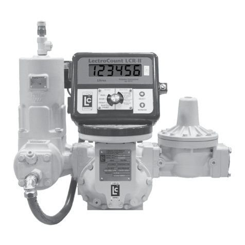
Liquid Controls
Liquid Controls LectroCount LCR-II E3655 Series User manual
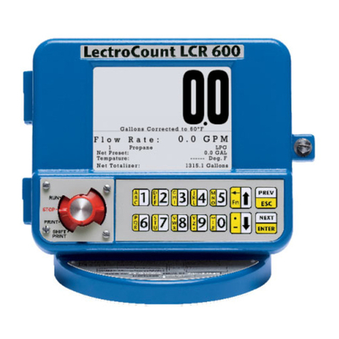
Liquid Controls
Liquid Controls LectroCount LCR 600 User manual
Liquid Controls
Liquid Controls M Series User manual
Liquid Controls
Liquid Controls LectroCount3 Reference guide
Liquid Controls
Liquid Controls MS Series User manual

Liquid Controls
Liquid Controls M Series User manual
Liquid Controls
Liquid Controls LectroCount LCR 600 E3708 Series User manual
Liquid Controls
Liquid Controls LectroCount LCR-II E3657 Series User manual
Liquid Controls
Liquid Controls A8981 User manual
Liquid Controls
Liquid Controls CENTRILOGiQ LCR.iQ Manual instruction
