manuals.online logo
Brands
  1. Home
  2. •
  3. Brands
  4. •
  5. Sealey
  6. •
  7. Test Equipment
  8. •
  9. Sealey BT2003.V4 User manual

Sealey BT2003.V4 User manual

1.1. PERSONAL PRECAUTIONS
Ensure that there is another person within hearing range and close enough to come to your aid, should a problem
arise when working near a lead-acid battery.
Wear safety eye protection and protective clothing. Avoid touching eyes while working near battery.
Have fresh water and soap nearby in case battery acid contacts skin, clothing, or eyes.
Wash immediately with soap and water if battery acid contacts skin or clothing. If acid enters eye, flush eye immediately with cool, clean running water for at
least 15 minutes and seek immediate medical attention.
Remove personal metallic items such as rings, bracelets, necklaces and watches. A lead-acid battery can produce a short-circuit current which is high enough
to weld such items to the vehicle and cause severe burns.
 Ensure that hands, clothing (especially belts) are clear of fan blades and other moving or hot parts of engine. Remove ties and contain long hair.
 DO NOT smoke or allow a spark or flame in the vicinity of the battery or engine.
1.2. GENERAL SAFETY INSTRUCTIONS
Familiarise yourself with the application, limitations and potential hazards of the tester. Also refer to the vehicle manufacturer’s hand book. IF IN ANY DOUBT
CONSULT A QUALIFIED ELECTRICIAN.
Ensure that the tester is in good condition before use. If in any doubt do not use the unit and contact a qualified electrician.
Only use recommended attachments and parts. To use unapproved items may be dangerous and will invalidate your warranty.
Keep tools and other items away from the engine and ensure that you can see the battery and working parts of engine clearly.
Determine the system voltage before using the tester.
If the tester receives a sharp knock or blow the unit must be checked by a qualified service agent before using.
If the battery terminals are corroded or dirty, clean them before using the tester.
Keep children and unauthorised persons away from the work area.
 DO NOT disassemble the tester for any reason. The tester must only be checked by qualified service personnel.
WARNING! To prevent the risk of sparking, short circuit and possible explosion DO NOT drop metal tools in the battery area, or allow them to touch the battery
terminals.
DO NOT cross-connect tester to battery. Ensure positive (RED) clamp is to positive terminal and negative (BLACK) clamp is to negative terminal. If battery
symbols cannot be distinguished, remember that the negative terminal is the one directly connected to the vehicle bodywork.
DO NOT use the tester outdoors, or in damp, or wet locations and DO NOT use in the vicinity of flammable liquids or gases.
 Ensure there is effective ventilation to prevent a build-up of explosive gases.
DO NOT use the tester for a task for which it is not designed.
 When not in use, store the tester carefully in a safe, dry, childproof location.
INSTRUCTIONS FOR:
DIGITAL BATTERY & ALTERNATOR
TESTER WITH PRINTER
MODEL: BT2003.V4
Thank you for purchasing a Sealey product. Manufactured to a high standard this product will, if used according to these instructions and properly maintained, give
you years of trouble free performance.
1. SAFETY INSTRUCTIONS
IMPORTANT: PLEASE READ THESE INSTRUCTIONS CAREFULLY. NOTE THE SAFE OPERATIONAL REQUIREMENTS, WARNINGS & CAUTIONS. USE THE PRODUCT
CORRECTLY AND WITH CARE FOR THE PURPOSE FOR WHICH IT IS INTENDED. FAILURE TO DO SO MAY CAUSE DAMAGE AND/OR PERSONAL INJURY AND WILL
INVALIDATE THE WARRANTY. PLEASE KEEP INSTRUCTIONS SAFE FOR FUTURE USE.
DANGER! BE AWARE, LEAD-ACID BATTERIES GENERATE EXPLOSIVE GASES DURING NORMAL BATTERY OPERATION. FOR THIS REASON, IT
IS VERY IMPORTANT TO READ AND FOLLOW THESE INSTRUCTIONS CAREFULLY, EACH TIME YOU USE THE BATTERY TESTER.
Follow these instructions and those published by the battery and vehicle manufacturers, and the maker of any equipment you intend to use in the
vicinity of the battery. Remember to review warning marks on all products and on engines.
3. OPERATION & USE
2. INTRODUCTION & SPECIFICATION
Professional diagnosis of battery and alternator faults with the added facility to print the results.
Test battery condition with as little as 1Volt of residual charge. No heat, no sparks and no misdiagnosis.
Checks condition of alternator - no complicated connections or interpretation required. Analyse the
charging system at rest and under load to determine condition of the alternator. Connect and follow the
prompts on the 2-line/16 character LCD screen for straightforward answers. Incorporates simple
voltmeter for voltage tests and additional system diagnostics. Rugged construction.
Supplied in sturdy carry-case with batteries, two rolls of printing paper and instruction manual.
 WARNING! Ensure that you read, understand and apply the safety and operational instructions before connecting the tester clamps to the battery. Only
when you are sure that you understand the procedures is it safe to proceed with the testing process.
3.1 PREPARATION
WARNING! Ensure that the vehicle, or battery, is in a well ventilated area before starting to test.
3.1.1 Check battery casing for cracks or leakage. If damage is found DO NOT test, replace battery.
3.1.2 Clean battery terminals.
3.1.3 If possible, check electrolyte levels and top-up with distilled water as necessary.
3.1.4 Unless otherwise specified tests are carried out with all electrical items switched off. Leaving any items on (boot light, interior light, etc.) can result in
misdiagnosis.
3.1.5 Confirm that the 4x AA Batteries (supplied) are correctly fitted in the compartment in the rear of the tester.
Note that nothing will be seen on the display until the tester is connected to a vehicle battery.
3.1.6 Connect the red clamp to the positive (+) battery terminal and the black clamp to the negative (-) terminal. When the internal battery becomes discharged
the display will read INTERNAL BATTERY LOW.
3.1.7 If there is a poor connection the display will read CHECK CLAMPS, otherwise the display will read either BATTERY TEST or SYSTEM TEST or
LANGUAGE.
3.1.8 Paper Load: Open the clear cover. Insert the paper in the feeder, it will auto feed in to the printer.
Rated Battery Voltage: . . . . . . . . . . . . . . . . . . . . 6-12V
Charging System Capability:.............. 12, 24V
Rated Systems: ............DIN, EN, IEC, JIS, SAE
Test Range: ....................25-1300CCA DIN
.................... 40-2100CCAEN
. . . . . . . . . . . . . . . . . . . . 30-1500CCA IEC
. . . . . . . . . . . . . . . . . . By battery type JIS
. . . . . . . . . . . . . . . . . . . 40-2000CCA SAE
Min. Power Requirement:.....................1V
Printer rolls (Pack of 2): . . . . . . . . . . . . . . . BT2003.01
Note: CCA = Cold Cranking Amps
BACK
ENTER
FORWARD
Original Language Version BT2003.V4 Issue: 1 - 08/10/10
Fig.1
3.3 BATTERY TEST
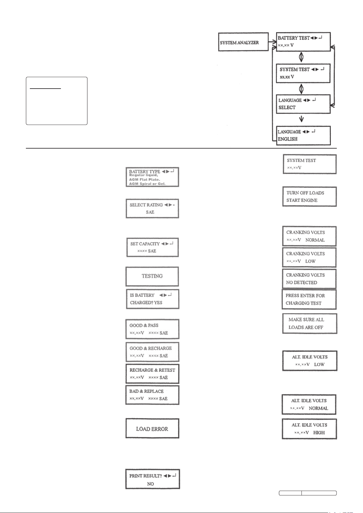
3.3.1 With battery test screen displayed
press ENTER.
3.3.2 Use the <(forward) and >(backward)
buttons to select the battery type:
Regular Liquid, AGM Flat Plate, AGM
Spiral, Gel.
Press ENTER to confirm choice.
3.3.3 Use the <(forward) and >(backward)
buttons to select the battery rating: SAE,
EN, IEC, DIN or JIS.
Press ENTER to confirm.
3.3.4 Use the <(forward) and >(backward)
buttons to input the battery capacity.
CCA:
DIN: 25 - 1300
EN: 40-2100
IEC: 30 - 1500
JIS: By battery type
SAE: 40 - 2000
Press ENTER to begin test.
3.3.5 Test Battery for 1 second.
3.3.6 Press <(forward) or >(backward) buttons
to select battery fully charged: Yes or No.
Press ENTER to confirm choice.
3.3.7 When the test is complete, the LCD
shows the actual volts and CCA.
One of the following results will be
displayed.
3.3.8 GOOD & PASS: Battery is capable of
holding a charge.
3.3.9 GOOD & RECHARGE: The battery is
good but needs to be recharged.
3.3.10 RECHARGE & RETEST: Battery is
discharged, the battery condition cannot
be determined until it is fully charged.
Recharge and retest.
3.3.11 BAD & REPLACE: The battery will not
hold its charge. Replace.
3.3.12 LOAD ERROR: The tested battery is
larger than 2000CCA or 200Ah. Or the
clamps are not connected properly.
Please fully charge the battery and retest
after excluding both previous reasons. If
reading is the same, the battery should
be replaced immediately.
NOTE! The operator is asked if any accessories
are left on as a possible cause. If
accessories are left on, the operator is
instructed to charge and retest the battery.
If accessories are not left on, the operator
is instructed to replace the battery since
the charging system is working and a good
battery should have accepted a charge.
3.3.13 Press <(forward) or >(backward) buttons
to select result printing: Yes or No. Press
3.2 DISPLAY GENERAL
By pressing the < (forward) and > (backward) buttons the display will cycle through
the options. Press ENTER button when the option you require is displayed.
3.2.1 System Analyser will display initially and then automatically switch to Battery Test.
3.2.2 Use the <(forward) and >(backward) buttons to cycle between System Test,
Language Select, and Battery Test. (Fig. 1)
ENTER to confirm choice.
3.3.14 Remove the clamps from the battery after
completion of testing.
3.4 SYSTEM TEST
3.4.1 Press "ENTER" button, you will view the
following screen.
3.4.2 Turn off all vehicle accessory loads such
as light, air conditioning, radio, etc.
before starting the engine.
3.4.3 When the engine is started, one of the
three results will be displayed along with
the actual reading measured.
3.4.4 CRANKING VOLTS NORMAL: The
system is showing normal draw. Press
ENTER to perform the charging
system test.
3.4.5 cranking volts low: The cranking
voltage is below normal limits,
troubleshoot the starter with
manufacturer’s recommended procedure
3.4.6 CRANKING VOLTS NO DETECTED:
The cranking voltage is not detected.
3.4.7 If the cranking voltage is normal, press
ENTER to begin charging system test.
3.4.8 Press the ENTER key, you will view the
following screen.
3.4.9 Press the ENTER key, one of the three
following results will be displayed along
with the actual reading measured.
LOW CHARGING VOLTS WHEN TESTED AT
IDLE: The alternator is not providing sufficient
current to the battery. Check the belt to ensure the
alternator is rotating with engine running. If the belt
is slipping or broken, replace and retest. Check the
connections from the alternator to the battery. If
the connection is loose or heavily corroded, clean
or replace the cable and retest. If the belt and
connections are in good condition, replace the
alternator.
CHARGING SYSTEM NORMAL WHEN TESTED
AT IDLE: The system is showing normal output
from the alternator. No problem is detected.
HIGH CHARGING VOLTS WHEN TESTED AT
IDLE: The voltage output from the alternator to the
battery exceeds the normal limits of a functioning
regulator. Check to ensure there are no loose
connections and the ground connection is good. If
there are no connection problems, replace the
regulator. Since most alternators have the
regulator built-in, this will require you to replace the
alternator. The normal limit of a typical automotive
regulator is 14.6 volts. Check manufacturer’s
specifications for the correct limit, as it will vary by
vehicle type and manufacturer.
Battery Type:
Regular liquid.
AGM Flat Plate.
AGM Spiral.
Gel.
Original Language Version BT2003.V4 Issue: 1 - 08/10/10
3.4.10 Following the charging system at idle,
press ENTER for the charging system
with accessory loads. Turn on the
blower to high (heat), high beam
headlights, and rear defogger. Do not use
cyclical loads such as air conditioning
or windshield wipers.
3.4.11 When testing older model diesel engines,
run the engine to 2500 rpm for 15
seconds.
3.4.12 Press ENTER to look for the amount of
ripple from the charging system to the
battery. One of two testing results will be
displayed along with the actual testing
measured.
3.4.13 RIPPLE DETECTED NORMAL: Diodes
function well in the alternator/stator.
3.4.14 EXCESS RIPPLE DETECTED: One or
more diodes in the alternator are not
functioning or there is stator damage.
Check to ensure the alternator mounting
is sturdy and that the belt is in good
shape and functioning properly. If the
mounting and belt are good, replace the
alternator.
3.4.15 Press the "ENTER" key to continue the
charging system test with accessory
loads. One of the following three results
will be displayed along with the actual
test measured.
OR
CHARGING SYSTEM HIGH WHEN TESTED
WITH ACCESSORY LOADS: The voltage output
from the alternator to the battery exceeds the
normal limits of a functioning regulator. Check to
ensure there are no loose connections and that
the ground connection is normal. If there are no
connection issues, replace the regulator. Since
most alternators have the regulator built-in, this
will require you to replace the alternator.
CHARGING SYSTEM LOW WHEN TESTED
WITH ACCESSORY LOADS: The alternator is
not providing sufficient current for the system's
electrical loads and the charging current for the
battery. Check the belt to ensure the alternator is
rotating with the engine running. If the belt is
slipping or broken, replace and retest. Check the
connections from the alternator to the battery. If
the connection is loose or heavily corroded, clean
or replace the cable and retest. If the belts and
connections are in good working condition,
replace the alternator.
CHARGING SYSTEM NORMAL WHEN TESTED
WITH ACCESSORY LOADS: The system is
showing normal output from the alternator. No
problem detected.
3.4.16 Press ENTER when charging system
test is completed. Turn all accessory
loads and engine off. Press ENTER to
return to step 1 or remove the test
clamps from the battery posts after
completion of testing to end test.
NOTE: It is our policy to continually improve products and as such we reserve the right to alter data, specifications and component parts without prior notice.
IMPORTANT: No liability is accepted for incorrect use of this product.
WARRANTY: Guarantee is 12 months from purchase date, proof of which will be required for any claim.
INFORMATION: For a copy of our latest catalogue and promotions call us on 01284 757525 and leave your full name and address, including postcode.
Sole UK Distributor, Sealey Group,
Kempson Way, Suffolk Business Park,
Bury St. Edmunds, Suffolk,
IP32 7AR
Original Language Version
01284 757500
01284 703534
sales@sealey.co.uk
www.sealey.co.uk
Web
email
Please note※ 24V SYSTEM TEST result can be printed when
connecting on 12V battery. Please refer to the following
instruction.
24V System Test Printing: T
he
printer
will
not
function
for
24
Volt
batteries
system
test printing.
The 24V system test result will be recorded until
you connect to a 12V battery and the correct
screen displays. Please select “YES” and press enter key to print
the result and then disconnect the clamps. The screen will appear
again after you reconnect the clamps. Please select “NO” and press
the enter key to go back to the main menu.
PRINT 24V SYSTEM
RESULT? YES
BT2003.V4 Issue: 1 - 08/10/10

Other Sealey Test Equipment manuals

Sealey TA131 User manual

Sealey

Sealey TA131 User manual

Sealey Auto Service BT91D.V2 User manual

Sealey

Sealey Auto Service BT91D.V2 User manual

Sealey TA301 User manual

Sealey

Sealey TA301 User manual

Sealey CT955.V2 User manual

Sealey

Sealey CT955.V2 User manual

Sealey VSE211.V4 Firmware update

Sealey

Sealey VSE211.V4 Firmware update

Sealey VS925 User manual

Sealey

Sealey VS925 User manual

Sealey VSE3158 User manual

Sealey

Sealey VSE3158 User manual

Sealey VS2030.V2 User manual

Sealey

Sealey VS2030.V2 User manual

Sealey VS2050 User manual

Sealey

Sealey VS2050 User manual

Sealey BT91/11 User manual

Sealey

Sealey BT91/11 User manual

Sealey AUTO SERVICE BT91/7C User manual

Sealey

Sealey AUTO SERVICE BT91/7C User manual

Sealey BT91/7.V4 User manual

Sealey

Sealey BT91/7.V4 User manual

Sealey CT955 V3 User manual

Sealey

Sealey CT955 V3 User manual

Sealey CV0011.V2 User manual

Sealey

Sealey CV0011.V2 User manual

Sealey CT955.V4 User manual

Sealey

Sealey CT955.V4 User manual

Sealey BT2012.V2 User manual

Sealey

Sealey BT2012.V2 User manual

Sealey BT2001 User manual

Sealey

Sealey BT2001 User manual

Sealey VS0031.V3 User manual

Sealey

Sealey VS0031.V3 User manual

Sealey TA120 User manual

Sealey

Sealey TA120 User manual

Sealey VSE2020.V3 User manual

Sealey

Sealey VSE2020.V3 User manual

Sealey VS2030.V2 User manual

Sealey

Sealey VS2030.V2 User manual

Sealey BT91/3.V2 User manual

Sealey

Sealey BT91/3.V2 User manual

Sealey BT91/3 User manual

Sealey

Sealey BT91/3 User manual

Sealey TA319 User manual

Sealey

Sealey TA319 User manual

Popular Test Equipment manuals by other brands

YATO YT-72986 Operating	 instruction

YATO

YATO YT-72986 Operating instruction

Tsuruga 8507 Operation manual

Tsuruga

Tsuruga 8507 Operation manual

Bosch EPS 200 operating instructions

Bosch

Bosch EPS 200 operating instructions

Macherey-Nagel Visocolor ECO Test instructions for visual determination

Macherey-Nagel

Macherey-Nagel Visocolor ECO Test instructions for visual determination

Tietzsch ProfiSafe LSP 4L User instructions

Tietzsch

Tietzsch ProfiSafe LSP 4L User instructions

Agilent Technologies 85052B User's and service guide

Agilent Technologies

Agilent Technologies 85052B User's and service guide

Rigol DS2000 Series Service guide

Rigol

Rigol DS2000 Series Service guide

Owon FDS Series user manual

Owon

Owon FDS Series user manual

Bedfont GastroCH4ECK Gastrolyzer user manual

Bedfont

Bedfont GastroCH4ECK Gastrolyzer user manual

Ebyte E78-868TBL-02 user manual

Ebyte

Ebyte E78-868TBL-02 user manual

Bante Instruments PHscan30L instruction manual

Bante Instruments

Bante Instruments PHscan30L instruction manual

Agilent Technologies N5341A installation guide

Agilent Technologies

Agilent Technologies N5341A installation guide

Dynatest FWD owner's manual

Dynatest

Dynatest FWD owner's manual

Agilent Technologies E7474A Getting started guide

Agilent Technologies

Agilent Technologies E7474A Getting started guide

Sumake TT-120 operating manual

Sumake

Sumake TT-120 operating manual

Keysight Technologies 16047A Operation and service manual

Keysight Technologies

Keysight Technologies 16047A Operation and service manual

Lovibond MINIKIT manual

Lovibond

Lovibond MINIKIT manual

Tektronix 420 Service manual

Tektronix

Tektronix 420 Service manual

manuals.online logo
manuals.online logoBrands
  • About & Mission
  • Contact us
  • Privacy Policy
  • Terms and Conditions

Copyright 2025 Manuals.Online. All Rights Reserved.