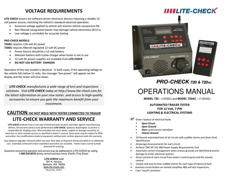
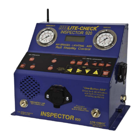
Lite-Check INSPECTOR 930 User manual

LITE-CHECK INSPECTOR 930
1
INSPECTOR MODEL 930
OPERATIONS MANUAL
LITE-CHECK VEHICLE TESTER
FOR
AIR BRAKES, ELECTRICAL AND ABS
REV 1.0.1 – Feb 9, 2023
“One Tool, One Person, One Process”
®
LITE-CHECK Fleet Solutions, Inc
301 N. Havana
Spokane, WA 99202
(800) 343-8579 or (509) 535-7512

LITE-CHECK INSPECTOR 930
2
REVISION HISTORY
REVISION DATE DONE BY
Tuesday July 12 2022 Bill H.
Thursday February 9 2023 Bill H.
1.0.0
1.0.1

LITE-CHECK INSPECTOR 930
3
Contents
Cautions........................................................................................................5
Introduction..................................................................................................6
Key Features of the Inspector 930.............................................................7
Overview.......................................................................................................8
Keyboard layout...........................................................................................9
Equipment and Setup................................................................................11
LITE-CHECK INSPECTOR 930 Accessories............................................12
Set-Up Procedures.....................................................................................13
Important Reminders.................................................................................13
Operations..................................................................................................14
Reading the Digital Display..................................................................................................................................14
7-Way Pin Numbers and Circuits..........................................................................................................................16
Remote Control.....................................................................................................................................................16
Power Supply........................................................................................................................................................17
7-Way Cable Test..................................................................................................................................................18
Trailer Test Procedures..........................................................................................................................................18
Air Brake Testing..................................................................................................................................................19
Inspecting for Trailer Electrical Faults..................................................................................................................20
ABS Test Procedures..................................................................................................................................................22
Tractor Testing......................................................................................................................................................28
Appendix.....................................................................................................29
Definition of Terms...............................................................................................................................................32
Accessories............................................................................................................................................................33
Inspector Trailer Interface and Tablet Setup...........................................34

LITE-CHECK INSPECTOR 930
4
Tablet Diagnostic Mode Features.............................................................38
Lite-Check Recommended Operation Procedures.................................38
Lite-Check Cloud........................................................................................41
Troubleshooting - Trailer Interface and Tablet........................................42
Warranty, Contact and Service Information............................................44
Shipping LITE-CHECK Products..............................................................44

LITE-CHECK INSPECTOR 930
5
Cautions
ØBlock vehicle wheels from movement before releasing brakes.
ØThe antenna must be fully exposed for a clear radio signal.
ØDo not weld while the tester is connected to the trailer. The 930 tester
is grounded to the chassis and will be damaged.
ØDo not hook up electrical devices on the same trailer that the tester is
diagnosing. The tester needs a clean power supply.
ØDo not lengthen the existing power cord on the tester. Attach the
tester power cord directly to a 12-volt battery or a regulated power
supply. Lengthening the power cord will cause a power drop.
ØBe aware of voltage spikes. The tester will only operate on regulated
power. Use a 12-volt battery or LITE-CHECK 325S Regulated Power
Supply.
ØDo not charge a battery while using the tester, except mobile
installations using a vehicle alternator. Using a battery charger as a
power source will damage the tester.
ØThe tester will not operate efficiently
below 11.0 volts and will indicate “LOW
BATTERY VOLTAGE”.
ØThe tester may shut down if the voltage drops below 9.0 volts.
ØIf operating gasoline motors near the tester, be sure that they have
static suppression on the engine. Static can cause radio interference.
ØThe emergency air must be applied before the service brakes will
operate.

LITE-CHECK INSPECTOR 930
6
LITE-CHECK INSPECTOR 930
Diagnostic Tester
Introduction
The LITE-CHECK INSPECTOR 930 Diagnostic Test System will perform vital
diagnostics of electrical and air systems on both tractors and trailers. The INSPECTOR
software puts trailer ABS inspection, fault identification and troubleshooting support at
the fingertips of inspectors and mechanics. The LITE-CHECK INSPECTOR 930
provides your facility with an efficient tool for safety assurance and maintenance of your
heavy-duty fleet.

LITE-CHECK INSPECTOR 930
7
Key Features of the Inspector 930
ØRemote control operation of electrical and air systems.
ØDynamic monitoring of electrical faults.
ØMicroprocessor-driven monitoring of all 7-way circuits allows direct
identification of circuit conditions including: shorts, opens, open
grounds, and chassis shorts.
ØDigital display provides fault information at the tester. Unique audible
alarms assist in troubleshooting and repair activities at various
locations around the trailer and tractor.
ØRegulated “Service Air” for consistent brake application and inspection.
ØPerforms one-step air-systems leak testing with a built-in 60 second
timer.
ØAutomatic cable test.
Ø“One-Button ABS” feature with direct access to faults present in ABS
controllers.

LITE-CHECK INSPECTOR 930
8
Overview
The LITE-CHECK INSPECTOR 930 has the following components:
ITEM DESCRIPTION
REMOTE CCONTROL ANTENNA Antenna for use with the remote control.
BLUETOOTH ANTENNA
Antenna used with a Bluetooth enabled tablet.
DIGITAL DISPLAY Displays messages on the tester status and results.
KEYPAD See page 7 for individual buttons
ALARM SPEAKER Speaker sounds different alarms for test failure.
EMERGENCY AIR CONNECTOR Port for connecting emergency air to the tester.
SERVICE AIR CONNECTOR Port for connecting Service air to the tester.
7-WAY CABLE SOCKET Cable socket for 7-way cable
SIDE 7-WAY CABLE SOCKET Cable socket for 7-way cable. (Used for cable testing)
ALARM SPEAKER
KEYPAD
EMERGENCY AIR CONNECTOR SERVICE AIR CONNECTOR
7-WAY CABLE SOCKET
DIGITAL DISPLAY
REMOTE CONTROL ANTENNA BLUETOOTH ANTENNA
SIDE 7-WAY SOCKET

LITE-CHECK INSPECTOR 930
9
The chart below provides a brief description of each button on the keyboard panel and
on the remote control.
Keyboard layout
Graphic Panel Button Remote Button Function
EMER EMER
Operates emergency
air
SERVICE SERVICE
Operates service air (if
emergency is
pressurized)
AIR LEAK TEST AIR LEAK TEST
Blocks air source for
vehicle air leak
BRAKE BRAKE
Operates brake
electrical circuit
MARKER MARKER
Operates marker
(clearance) circuit
AUXIL AUXIL
Operates auxiliary
circuit (ABS power)
LEFT LEFT
Operates Left turn
circuit
TAIL TAIL Operates tail circuit
EMER
SERVIC
AIR
LEAK
TEST
BRAKE
MARKER
AUX
LEFT
TAIL

LITE-CHECK INSPECTOR 930
10
Graphic Panel Button Remote Button Function
RIGHT RIGHT
Operates right turn
circuit
ABS BACK ABS BACK
ABS Test - Initiates the
ABS test routine (30 to
45 seconds)
SELECT* HELP SELECT* HELP
ABS Select - Enter
selected option or view
on screen
DOWN DOWN
Moves display cursor
down
UP UP
Moves display cursor
up
(NO TEXT) N/A
Non Functional - for
future use
ALARM MUTE N/A
Turns alarm off during
electrical test
TRACTOR
OUTPUT/CABLE TEST
N/A
Tractor output test/
cable test
RIGHT
ABS
BACK
SELECT
HELP
DOWN
UP
ALARM
MUTE
TRACTOR
OUTPUT
TEST
CABLE TEST
Multiple circuits can be activated at the same time by using the “SELECT” button
on the tester or on the remote. In this mode, multiple circuits can be switched on
and off, with the display indicating the total current draw of all the circuits. Pressing
the “SELECT” button once again will exit this mode.
*SELECT Detail:

LITE-CHECK INSPECTOR 930
11
What is included with the LITE-CHECK INSPECTOR 930?
The INSPECTOR 930 ships with the following items:
1 – LITE-CHECK INSPECTOR 930
1 – Inspector 930 Operations Manual
1 – Quick Reference Guide
1 – Protective Dust Cover
1 – Remote Control
1 – Plastic Remote Cover
1 – Orange Neck Pouch For Remote
Please inspect the shipment when it arrives for any missing or damaged items.
Required Materials
The following additional materials are required to operate the INSPECTOR 930:
·1 – 7-way cable with 7-way plugs on both ends
·2 – 1/4” air lines with glad-hands on one end
·2 – Quick disconnect air connectors (male and female for tester and air lines)
·1 – Filtered air regulator to provide clean 110-120psi air pressure
Note: The above Items are available in the LITE-CHECK 302A Shop Accessory
Kit. (See LITE-CHECK INSPECTOR 930 Accessories on page 10.)
·1 – Power supply (Either the LITE-CHECK 325S 12VDC Regulated Power Supply OR a
charged 12-volt battery.)
Note: Power to the tester must be regulated to protect the trailer’s ABS
electronics and ensure consistent tester performance.
·Mounting location or plate to secure the Inspector 930 tester.
Warning: The LITE-CHECK INSPECTOR 930 is a “diagnostic” tester that monitors the
current flow through the ground circuit to aid in identifying various fault conditions. Care
should be taken to insure that the tester’s case is not grounded to the trailer or tractor
under test. D O N O T s u p p l y t he Inspector 930 with power from the tractor when testing and
inspecting tractor/trailer combinations.
Equipment and Setup
The LITE-CHECK Inspector 930 diagnostic tester is designed for easy operation and
setup. Some additional items are required to fully utilize all of the 930’s functions.

LITE-CHECK INSPECTOR 930
12
LITE-CHECK INSPECTOR 930 Accessories
Besides the provided items, the following LITE-CHECK items are available to enhance the
INSPECTOR 930:
●Lite-Check 325S 12VDC Regulated Power Supply
●331A Pedal Actuator
●301M Service Truck Kit
◘Kit Includes:
n2 - 20 FT Air Lines
n1 - 20 FT 7-Way cable with 7-Way plugs on both ends
n1 - Air filter regulator
●302A Shop Accessory Kit
◘Kit Includes:
n2 - 8 FT Air Lines
n1 - 8 FT 7-Way cable with 7-Way plugs on both ends
n1 - 1 Air filter regulator
●Model 300P Shop Cart Kit
◘Kit Includes:
n1 - Knock down 4-wheeled cart with air lines
n1 - 8 FT 7-Way cable with 7-Way plugs on both ends
n2 - 8 FT Air lines
n1 - Air filter regulator
nNecessary hardware for easy set-up in the shop

LITE-CHECK INSPECTOR 930
13
Set-Up Procedures
The following steps should be taken to ensure proper setup of the INSPECTOR 930:
1. Read the Operations Manual and the Quick Reference Guide.
2. Mount the Tester securely.
3. Connect the INSPECTOR 930 Tester to a regulated 12 Volt, 20 amp capable power
supply.
Warning: A 12 volt battery charger cannot be used, applied power must be clean
(filtered and regulated) and capable of generating 20 amps.
4. Connect the air supply to the tester on the side panel through a filtered regulator.
(110 to 120 psi is recommended.)
5. Connect the red battery clamp or ring terminal to the positive output.
6. Connect the black battery clamp or ring terminal to the negative output.
Important Reminders
ü Do not use battery chargers as a power supply – Battery Chargers are non-
regulated and may cause damage to the ABS ECU, or the tester.
ü Do not charge a battery while using the tester, except mobile installations
using a vehicle alternator.
ü The tester will not operate reliably below 11.0 volts and will indicate a “Low
Battery Voltage” condition” (LOW BAT).
ü The tester will completely shut down if the voltage drops below 9.0 volts.
ü Be sure the air pressure supply is above 90 psi if the tester is used for air brake
inspections. (110 to 120 psi input air with regulator is recommended.)
Note: If the 930 will not operate, check if the 12 volt power line polarity is reversed. Refer to steps
5 and 6 of the set-up procedures.

LITE-CHECK INSPECTOR 930
14
Operations
Reading the Digital Display
The digital display on the INSPECTOR 930 provides a range of error messages that indicate
operational status. The following are examples only. The full list of messages is shown with the
appropriate test procedure.
DISPLAY DETAIL
The first screen appears on the display for
several seconds.
This screen displays this message when the
tester is ready for operations.
●VDC is the voltage at the tester
●AMP is the circuit amperage the tester is
reading.
●AUX, BLUE, PIN 7 indicates 7-way PIN
number and circuits are currently being tested.
●Electrical circuits will display “GOOD” if greater
than 0.005 amps and less than 20 amps and
no other faults are found.

LITE-CHECK INSPECTOR 930
15
DISPLAY DETAIL
“SHORT” - Shorted circuit fault
Fault with multiple circuits involved when a single
circuit is under test. The tester has identified
electrical activity on more than one circuit.
The panel circuit indicator lights illuminate for all
shorted circuits, and the “SHORT” fault alarm
sounds. The digital display indicates the circuit
under test, current draw, voltage, and a
SHORTED circuit fault. Amperage shows the
total circuit load on the digital display.
This screen is identifying a short between the
MARKER and the TAIL circuits. The shorted
circuit on the marker will be illuminated on the
tester panel.
“CHASSIS SHORT” - Ground Fault
Fault with circuit supply wire in contact with
the chassis or ground circuit.
The panel circuit indicator light is on and the
“CHASSIS” fault alarm sounds. Current to the
trailer is restricted, and the digital displays 29.99
amperage.
This screen shows the BRAKE circuit wire is
shorted. The 930 frimware protects the vehicle
harness by pulsing the power every one second.

LITE-CHECK INSPECTOR 930
16
Operation
·
Press and release the designated button.
·
Inspect. One light circuit will be activated at a time.
·
The Remote Control is keyed to operate with a single unique
tester at a time.
·
Remote Control operations are parallel to the panel keypad.
·
Range is over 100 feet with AA batteries in good condition.
7-Way Pin Numbers and Circuits
7-WAY PIN
NUMBER WIRE COLOR CIRCUIT
1 WHITE GROUND
2 BLACK MARKER
3 YELLOW LEFT TURN
4 RED BRAKE
5 GREEN RIGHT TURN
6 BROWN TAIL
7 BLUE AUXILIARY
Remote Control
The remote control allows the vehicle technician to operate air and electrical functions around the
vehicle and observe the responses.
AIR TESTING
ELECTRICAL TESTING
ABS TESTING

LITE-CHECK INSPECTOR 930
17
·The sending lamp will light up when the button on the remote control is pressed.
Power Supply
The tester is designed for negative ground vehicles (black-negative, red-positive). In
case of reversed battery leads on the power cable, the tester will not operate.
Power Supply Set Up:
Attach the battery cable clamps (or ring terminals) to a 12VDC automotive battery, or a
regulated power supply (such as the LITE-CHECK 325S).
·Black battery cable to negative –
·Red battery cable to positive +
Turn the power switch on (located on the back panel of the tester) for operation.
Low Battery Messages
NOTE: The tester will not work properly if the battery is not charged to a full 12+volts.
The tester will not operate and will possibly lock up if the power is below 11.0 volts,
and will turn off it’s power if it’s below 9.0 volts.
Notes:
·Replace (4) AA batteries if the sending lamp does not illuminate.
·Remove the batteries using the pull strap inside the case. Do not pry them
out.
·If remote controls need to be keyed to different testers, contact LITE-CHECK
for assistance.
·The tester antenna must be fully exposed for proper signal reception.

LITE-CHECK INSPECTOR 930
18
7-Way Cable Test
The 7-way cable test automatically tests the 7-Way 7-pin vehicle cable.
Place tester in tractor mode. (Push TRACTOR OUTPUT TEST button on the
tester panel.)
1. Plug in the cable in the front 7-way socket and the 7-way socket on the right side
of the tester.
2. The tester will automatically read the pins and display either “PASS” or “FAIL” for
each pin in the socket.
3. If there is a “FAIL” message on the digital display, the following will be indicated:
a. A blank second line in the pin sequence indicates an OPEN circuit.
b. “MIS-WIRE” indicates a reversed pin.
c. The same pin number on the second line indicates a “SHORT”.
Trailer Test Procedures
Before beginning testing, connect a 7-way cable and two 1/4” glad hands airlines from
the tester to the trailer. (Be careful to connect “service” to service and “emergency” to
emergency.)
1. Ensure voltage from power source is above 11.0 VDC. (Anything lower may cause
faulty readings.)
2. Use either the tester panel buttons or the remote control buttons.
3. The tester’s panel circuit indicator lights will illuminate when the tester is
operating.
4. The digital display will show the electrical status.
5. The digital display will show the air application pressure.
TRACTOR
OUTPUT
TEST
CABLE TEST
Display Details
The tester message “LOW BATTERY VOLTAGE”
indicates that the 12-volt battery powering the tester
needs to be recharged. The tester will display the
voltage

LITE-CHECK INSPECTOR 930
19
Air Brake Testing
Once the INSPECTOR 930 is connected to air and power, and to the tester, the air and
brake system testing can begin.
2. Press the “SERVICE” button to set service brakes. (Regulated at 90 to
95psi.)
3. Identify and record the current air pressure shown on the digital display.
4. Press the “AIR LEAK TEST” button to perform the air Observe the digital display
for changes.
Min/sec
5. A timer will start on the digital display at 00:00 and count up to 59:59 (minutes
and seconds).
6. Watch for any changes on either line.
a. If one line falls, there is an external air leak.
b. If the lines equalize, there is an internal air leak.
7. The Emergency line is allowed 3 pounds of air loss in one minute.
8. The Service line is allowed 2 pounds of air loss in one minute.
AIR
LEAK
TEST
Press the “EMER” button to apply air to the trailer and release the parking
brakes. (Source air at 110 to 120 psi)
EMER
SERVICE
1.
9. Press the “EMER” button to release the emergency air.
NOTE: Emergency air must be applied before service brakes will operate. This
prevents the brakes from compounding.

LITE-CHECK INSPECTOR 930
20
Inspecting for Trailer Electrical Faults
Overview
Always begin the inspection operation with a properly setup INSPECTOR 930.
Adequate air and 12-volt power should be verified before starting the test.
NOTE: Air and air connections are not required when performing electrical inspections
only.
LITE-CHECK automatic testers are programmed to concurrently monitor all of the wires
on the 7-way cable connecting the tester to the trailer. This provides immediate
feedback on the conditions of each electrical circuit under test.
Electrical faults are signaled by the tester.
Electrical circuits that have burned-out, or have damaged lamps may still have properly
operating lamps AND the circuit will not indicate a fault. The tester’s digital display can
be used to observe the current drawn by each circuit and to look for unusual variances
from the expected values.
NOTE: If more than one fault is detected, the tester will identify the faults in the order of
the “Fault Detection Hierarchy” list on page 20. Once the first fault is corrected, the
tester will go to the next fault and so on until all the faults have been cleared.
Electrical Testing
In normal operating mode only ONE electrical circuit will operate at a time. The digital
display will show amperage, voltage and circuit condition. The corresponding electrical
indicator LED will be lit.
1. Start at the front corner of the trailer and observe the lights. Press the button for
the circuit being tested. Each light must be visually inspected to ensure it is
good.
2. Move to the next corner of the trailer and continue the light inspection.
Table of contents
Other Lite-Check Test Equipment manuals
Popular Test Equipment manuals by other brands

ScanTools
ScanTools ECUsim 5100 user guide

Fluke
Fluke CableAnalyzer DTX-1500 Technical reference handbook

Industrial Scientific
Industrial Scientific DS2 Docking Station Administrator's guide

palintest
palintest Pooltest 3 manual

Insoric
Insoric RealPower Technical description

DelAgua
DelAgua Portable Water Testing Kit user manual

Agilent Technologies
Agilent Technologies InfiniiVision 3000 X- Series Advanced training guide

Gilson
Gilson HM-353 operating manual

Benning
Benning duspol expert operating manual

Extech Instruments
Extech Instruments CG304 user manual

Ametek
Ametek LS1 Series user manual

SKI
SKI 18BDC Owner's/operator's manual