Lite-Puter DP-E500 User manual

ISO 9001 CERTIFIED www.liteputer.com.tw
1 Lite-Puter
DP-E500[EUM-B]
DP-E500
Ethernet to DMX Interface
【User Manual】
Lite Puter Enterprise Co., Ltd.
Website: www.liteputer.com.tw
Email:sales@liteputer.com.tw

ISO 9001 CERTIFIED www.liteputer.com.tw
2 Lite-Puter
DP-E500[EUM-B]
Index
1Introduction....................................................................................................4
1-1Feature.................................................................................................4
1-2Specification.........................................................................................4
1-3Dimension............................................................................................5
1-4Function ...............................................................................................5
1-5System Diagram...................................................................................6
2 Operation......................................................................................................8
2-1Work with Home Lighting Control Software..........................................8
2-1-1 Main Menu Introduction....................................................................9
F1 SCENE EDIT........................................................................................9
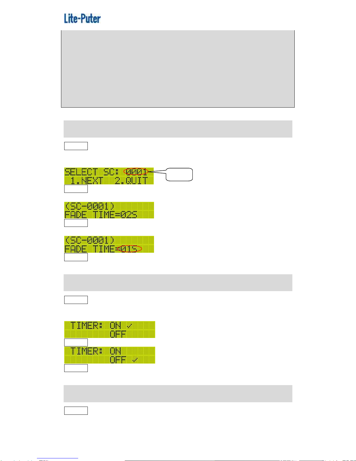
F2 SCENE FADE.....................................................................................10
F3 TIMER ON/OFF..................................................................................10
F4 TIMER EDIT.......................................................................................10
F5 SCH EDIT...........................................................................................12
F6 PATCH EDIT.......................................................................................13
F7 PATCH LOAD.....................................................................................14
F8 MODIFY CLOCK................................................................................14
F9 SET IP................................................................................................14
F10 SET MAC..........................................................................................15
F11 ABOUT ME.......................................................................................15
2-1-2 Memory Initialization.......................................................................15
2-1-3 Key Lock/Unlock.............................................................................16
2-1-4 Other..............................................................................................16
2-1 Work with RGB LED Control Software...............................................17
2-2-1 Main Menu .....................................................................................18
F1 CALL SEQ.........................................................................................18
F2 MODIFY CH.......................................................................................19
F3 EDIT SCENE.....................................................................................20
F4 LOAD BACKSC.................................................................................20
F5 EDIT SEQ..........................................................................................21
F6 SEQ CONFIG....................................................................................21
F7 TIMER ON/OFF.................................................................................22
F8 EDIT TIMER ......................................................................................23
F9 EDIT PATCH......................................................................................25
F10 EDIT CLOCK...................................................................................26
F11 SET IP..............................................................................................26
F12 SET MAC.........................................................................................26
F13 ABOUT ME......................................................................................27
2-2-2 IR Remote Control..........................................................................27
2-2-3 Memory Initialization.......................................................................27
2-2-4 Key Lock/Unlock.............................................................................27
2-2-6 Other..............................................................................................28
2-3Work with Lighting Control Software ..................................................29
2-3-1 Main Menu Introduction..................................................................30
F1 SET IP...............................................................................................30
F2 SET MAC...........................................................................................30
F3 MODIFY CLOCK ...............................................................................30
F4 ABOUT ME........................................................................................31

ISO 9001 CERTIFIED www.liteputer.com.tw
3 Lite-Puter
DP-E500[EUM-B]
2-3-2 Memory Initialization.......................................................................31
2-3-3 Key Lock/Unlock.............................................................................31
2-3-4 Other..............................................................................................32
2-4Control Software Shift ........................................................................32
Limited Warranty............................................................................................33

ISO 9001 CERTIFIED www.liteputer.com.tw
4 Lite-Puter
DP-E500[EUM-B]
1Introduction
1-1 Feature
Ethernet to DMX and DMX to Ethernet transformation.
Can be used as a controller.
Connectable to PC and control software in PC can save the setting and
copy the setting data. There are 4 control software can work with DP-E500
and it can automatically shift the function according to each control
software.
After saving the data on DP-E500, it can work alone.
2 DMX -512 outputs for control up to 1204 channels.
Large memory for save scene, timer and channel setting.
Chaser function:
Scene chaser
Chaser speed adjustment
Color mix
Timer load function.
System update online.
IR remote control function.
LCD display and user-friendly interface.
Light, handy and portable.
1-2 Specification
Power supply :AC 100V-240V,50-60Hz
Protocol: DMX-512/1990
Signal connector: 6P6C PHONE JACK * 6, XLR 5-PIN * 4
Dimension: 482( W ) *44 ( H ) * 130( D ) mm
Weight: 1.6Kg

ISO 9001 CERTIFIED www.liteputer.com.tw
5 Lite-Puter
DP-E500[EUM-B]
1-3 Dimension
1-4 Function
1
LCD screen
2
Link and data indicator
3
Function button
4
Number button and indicator
5
IR receiver
6
DMX port
7
Ethernet port
8
DMX port
9
Power switch
10
AC power input
1
2
3
4
5
6
7
8
9
10

ISO 9001 CERTIFIED www.liteputer.com.tw
6 Lite-Puter
DP-E500[EUM-B]
1-5 System Diagram
Diagram 1(EDX)
DP-E500
EDX-610
Control Panel
IR Controller
Ethernet Signal
EDX Signal

ISO 9001 CERTIFIED www.liteputer.com.tw
7 Lite-Puter
DP-E500[EUM-B]
Diagram 2(DMX)
DX-1220
……….
DP-E500
Ethernet Signal
DMX Signal

ISO 9001 CERTIFIED www.liteputer.com.tw
8 Lite-Puter
DP-E500[EUM-B]
2 Operation
2-1 Work with Home Lighting Control Software
When DP-E500 work with Home Lighting software, its DMX1 port sent
DMX-512 signal to the controller and DMX2 port receive the signal from the
ECP control panel. The max. control channel quantity is 512.
System Diagram(Home Lighting Control Software )
DP-E500
EDX-610
Control Panel
IR Controller
Ethernet Signal
DMX Signal
EDX Signal

ISO 9001 CERTIFIED www.liteputer.com.tw
9 Lite-Puter
DP-E500[EUM-B]
2-1-1 Main Menu Introduction
Select any one function from F1 to F11 and press【ENT】to enter the function.
F1 SCENE EDIT
STEP-1 On the main page, press【FCN】to enter the main menu.
STEP-2 Press【▲】or【▼】to select F1 SCENE EDIT and press【ENT】
enter the function and LCD displays,
STEP-3 Press【▲】or【▼】to select the scene no.; press【1】to continue or
press【2】to quit. Press【1】and LCD displays,
STEP-4 Press【◀】or【▶】to select the channel no. and【▲】or【▼】to adjust
the dimming value.
STEP-5 After setting, press【ENT】and LCD displays,
Press【1】to save the setting to SC0001 or press【2】to quit.
Notice: After DP-E500’s connecting with Home Lighting control software,
the scene button on DP-E500 will have new meaning.
【OFF】is for SC1
【1】is for SC2
【2】is for SC3 and so on.
If the dimming value set as NC, it means this channel will not be output
Blink
Channel dimming value
Blink

ISO 9001 CERTIFIED www.liteputer.com.tw
10 Lite-Puter
DP-E500[EUM-B]
when the scene include this channel was call out and this channel will
remain the dimming value that set in last scene.
For example:
SC1’s 1 to 4 channel was set as 100%,100%,0%,0%;
SC2’s 1 to 4 channel was set as NC,NC,20%,30%;
Recall SC1, the output will be 100%,100%,0%,0%;
Recall SC2, the output will be 100%,100%,20%,30%。
F2 SCENE FADE
STEP-1 On the main page, press【FCN】to enter the main menu and press
【▲】or【▼】to select F2 SCENE FADE. Press【ENT】to enter the function and
LCD displays,
STEP-2 Press【▲】or【▼】to select the scene no.;press【1】to continue or
press【2】to quit. Press【1】and LCD displays,
STEP-3 Press【◀】or【▶】to select the scene no. again or press【▲】or【▼】
to adjust the fade time.
STEP-3 After setting, press【ENT】to save or press【FCN】to quit.
F3 TIMER ON/OFF
STEP-1 On the main page, press【FCN】to enter the main menu and press
【▲】or【▼】to select F3 TIMER ON/OFF. Press【ENT】to enter the function
and LCD displays,
STEP-2 Press【▲】or【▼】to select on or off.
STEP-3 After setting, press【ENT】to save or press【FCN】to quit.
F4 TIMER EDIT
STEP-1 On the main page, press 【FCN】to enter the main menu and press
【▲】or【▼】to select F4 TIMER EDIT. Press【ENT】to enter the function and
Blink

ISO 9001 CERTIFIED www.liteputer.com.tw
11 Lite-Puter
DP-E500[EUM-B]
LCD displays,
STEP-2 Press【▲】or 【▼】to set CELEBRATE, DAY PTH, MONTH PTH,
WEEK PTH one by one.
1)CELEBRATE
STEP-1 Select F3-1, press【ENT】and LCD displays,
2DEL:Delete timer 3ADD:Add timer 4EDIT:Edit timer
STEP-2 Press【◀】or【▶】to review all the timer.
Add Timer
STEP-1 Enter F3-1 and press【3】to add a timer.
STEP-2 Press【◀】or【▶】to select month, day and schedule no. and press
【▲】or【▼】to adjust the value.
STEP-3 After setting, press【ENT】to save or press【FCN】to quit.
Repeat STEP-1 to STEP-3 to add more timers.
Edit Timer
Review the timer record to select one need to edit. Press【4】and LCD displays,
Repeat STEP-2 and STEP-3 in add timer to do the following setting.
Delete Timer
Review the timer record to select one need to edit. Press【2】and LCD displays,
Blink
Blink
Blink

ISO 9001 CERTIFIED www.liteputer.com.tw
12 Lite-Puter
DP-E500[EUM-B]
Press【1】to confirm the deletion or press 【2】to exit.
2)DAY PTH
STEP-1 Selec F3-2, press【ENT】and LCD displays,
STEP-2 Press【◀】to【▶】select the day; press【▲】or【▼】to select
the schedule no..
STEP-3 After setting, press【ENT】to save or press【FCN】to exit.
3)MONTH PTH
STEP-1 Select F3-3, press【ENT】and LCD displays,
STEP-2 Press【◀】or【▶】to select the month ;press【▲】or【▼】to select
the schedule no..
STEP-3 After setting, press【ENT】to save or press【FCN】to exit.
4)WEEK PTH
STEP-1 Select F3-4, and press【ENT】and LCD displays,
STEP-2 Press【◀】or【▶】to select the week day; press【▲】or【▼】to select
the schedule no..
STEP-3 After setting, press【ENT】to save or press【FCN】to exit.
Notice: If the Schedule set as SCH000, it means there is no schedule will
be executed.
F5 SCH EDIT
STEP-1 On the main page, press 【FCN】to enter the main menu and press
【▲】or【▼】to select F5 SCH EDIT. Press【ENT】to enter the function and
LCD displays,
It means schedule 1 will be executed on the first
day of each month .
It means schedule 2 will be executed on the
January of each year.
It means schedule 1 will be executed on the
Monday of each week.

ISO 9001 CERTIFIED www.liteputer.com.tw
13 Lite-Puter
DP-E500[EUM-B]
STEP-2 Press【▲】or【▼】to select the Schedule no.. After selection, press
【1】to continue or press【2】to quit. Press【1】and LCD displays,
STEP-3 Press【◀】or【▶】to review all the timer.
2DEL:Delete timer 3ADD: Add timer 4EDIT: Edit timer
Please refer to the operation of F4:TIMER EDIT.
F6 PATCH EDIT
The PATCH has 2 functions: first, make 1 channel control several DMX
address; second, rearrange the DMX address’order.
one channel no. to several channel address
DMX address 1
CH 001
DMX address 2
CH 001
DMX address 13
CH 001
DMX address 27
CH 001
DMX address 139
CH 001
DMX address 508
CH 001
Now, CH001 control DMX address1, 2, 13, 27, 139, 508.
STEP-1 On the main page, press【FCN】to enter the main menu and press
【▲】or【▼】to select F6 PATCH EDIT.Press【ENT】to enter the function and
LCD displays,
STEP-2 Press【▲】or【▼】to select the PATCH no. then press【1】to continue
or press【2】to exit. Press【1】and LCD displays,
STEP-3 Press【▲】or【▼】to select the channel no. and press【◀】or【▶】
to select DMX address.
Executing time
Scene no. and fade time
Blink

ISO 9001 CERTIFIED www.liteputer.com.tw
14 Lite-Puter
DP-E500[EUM-B]
STEP-4 Afer setting, press【ENT】and LCD displays.
Press【1】to save the setting to PATCH 01 or press【2】to exit.
F7 PATCH LOAD
STEP-1 On the mian page, press【FCN】to enter the main menu and press
【▲】or【▼】to select F7 PATCH LOAD. Press【ENT】and LCD displays,
STEP-2 Press【▲】or【▼】to select the PATCH and LCD displays,
Notice: The default setting is DF, which means the channel is correspond
to each DMX address exactly.
STEP-3 After setting, press【ENT】to save or press【FCN】to exit.
F8 MODIFY CLOCK
STEP-1 On the main page, press【FCN】to enter the main menu and press
【▲】or 【▼】to select F8 MODIFY CLOCK. Press【ENT】and LCD displays,
STEP-2 Press【◀】or【▶】to select the year, month, day , week, hour, minute,
second then press【▲】or 【▼】to adjust the value.
STEP-3 After setting, press【ENT】to save or press【FCN】to exit.
F9 SET IP
STEP-1 On the main page, press 【FCN】to enter the main menu and press
【▲】or【▼】to select F9 SET IP. Press【ENT】and LCD displays,
Channel 5 controls DMX address 001.
Blink
Blink
Load PATCH 01
Blink

ISO 9001 CERTIFIED www.liteputer.com.tw
15 Lite-Puter
DP-E500[EUM-B]
STEP-2 Press【◀】or 【▶】to select the byte and press【▲】or【▼】to adjust
the value.
STEP-3 After setting, press【ENT】to save or press【FCN】to exit.
Notice: Please make sure that the network don’t have same IP
F10 SET MAC
STEP-1 On the main page, press【FCN】to enter the main menu and press
【▲】or 【▼】to select F10 SET MAC. Press【ENT】and LCD displays,
STEP-2 Press【◀】or 【▶】to select the byte and press【▲】or【▼】to adjust
the value.
STEP-3 After setting, press【ENT】to save or press【FCN】to exit.
F11 ABOUT ME
On the main page, press【FCN】to enter the main menu and press【▲】or【▼】
to select F11 ABOUT ME, press【ENT】and LCD displays,
2-1-2 Memory Initialization
STEP-1 After switching off, hold 【FCN】and 【OFF】at the same time then
switch DP-E500 on till LCD displays,
Press【1】to start the initialization or press【2】to skip.
STEP-2 Press【1】to initializa the memory and LCD displays,
then
Blink
Blink
Work with Home-Lighting
Software version:V1.17

ISO 9001 CERTIFIED www.liteputer.com.tw
16 Lite-Puter
DP-E500[EUM-B]
2-1-3 Key Lock/Unlock
If the key on the unlock status, hold【ENT】for 3 seconds to lcok the key and
LCD displays,
If the key on the lock status, hold【ENT】for 3 seconds to unlcok the key and
LCD displays,
2-1-4 Other
A. When the DP-E500 is working alone, LCD displays,
DP-E500’s IP address is 192.168.2.67.
B. When the DP-E500 is working with the control software, LCD displays,
PC’s IP address is 192.168.2.99.
C. Press【FCN】to go back to the main page.
D. After connecting with Home-Lighting control software, the data of Scene,
Schedule and Patch can be transmit between PC and DP-E500.

ISO 9001 CERTIFIED www.liteputer.com.tw
17 Lite-Puter
DP-E500[EUM-B]
2-1 Work with RGB LED Control Software
When DP-E500’s working with RGB LED control software, DP-E500 will
receive Ethernet signal and its DMX1 & DMX 2 port will send DMX-512 signal
to control the LED devices, the max. control channel quantity is 1024.
System Diagram (RGB LED Control Software)
DP-E500
Ethernet signal
DMX signal

ISO 9001 CERTIFIED www.liteputer.com.tw
18 Lite-Puter
DP-E500[EUM-B]
2-2-1 Main Menu Introduction
Select any one function from F1 to F11 and press【ENT】to enter the function.
F1 CALL SEQ
STEP-1 On the main page, press【FCN】to enter the main menu,
STEP-2 Press【▲】or【▼】to select F1 CALL SEQ and press【ENT】and
LCD displays,
STEP-3 Press【▲】or【▼】to select the SEQ no..
After setting, press【1】to save and press【2】to exit.
Notice :
1. When the SEQ OFF and SEQ 001-SEQ 006 be recalled , the indicator of
key【OFF】and 【1】-【6】will turn on; but when SEQ 007-SEQ 512 be
recalled, there is no indicator sign.
2. On the main page, press 【OFF】and 【1】-【6】to recall SEQ OFF and
SEQ 001-SEQ 006 directly.
Blink

ISO 9001 CERTIFIED www.liteputer.com.tw
19 Lite-Puter
DP-E500[EUM-B]
Pause and Turn off SEQ
When SEQ 001 be recalled, LCD displays,
Press【OFF】to pause the current SEQ and LCD displays,
Press【OFF】again to continue the current SEQ.
Hold【OFF】for 3 seconds to turn off the SEQ( all channel’s dimming value is
0%) and LCD displays,
F2 MODIFY CH
Set each channel’s dimming value and save the setting to any scene.
Notice:
After enter this function, all the SEQ will stop and the output will be the
current step’s scene.
All the channel’s dimming value setting will be output immediately.
STEP-1 On the main page, press【FCN】to enter the main menu and press
【▲】or【▼】to select F2 MODIFY CH. Press【ENT】and LCD displays,
STEP-2 Press【◀】or【▶】to select the channel no., and press【▲】or【▼】
to adjust the dimming value.
STEP-3 After settting, press【ENT】to save or press【FCN】to exit.
STEP-4 Press【ENT】and LCD displays,
STEP-5 Press【▲】or【▼】to select the scene no.need to save to.

ISO 9001 CERTIFIED www.liteputer.com.tw
20 Lite-Puter
DP-E500[EUM-B]
STEP-6 After setting, press【1】to save or press【2】to exit.
F3 EDIT SCENE
DP-E500 can save 512 scenes and scene no.is 0-512. If the scene is
SC000, any dimming value change is started from 0%. If the scene is
SC001-SC512, any dimming value change is started from the last setting.
Notice:
After enter F3 EDIT SCENE function, the SEQ will keep executing. All the
channel’s dimming value setting will not be output immediately.
STEP-1 On the main page, press【FCN】to enter the main menu and press
【▲】or【▼】to select F3 EDIT SCENE. Press【ENT】and LCD displays,
STEP-2 Press【▲】or【▼】to select the scene no. and press【1】to continue
or press【2】to exit. Press【1】and LCD displays,
STEP-3 Press【◀】or【▶】to select the channel no. and press【▲】or【▼】
to adjust the dimming value.
STEP-4 After setting, press【ENT】to save and press【FCN】to exit.
STEP-5 Press【ENT】and LCD displays,
STEP-6 Press【▲】or【▼】to select the scene no. need to save to .
STEP-7 Press【1】to save or press【2】to exit.
F4 LOAD BACKSC
STEP-1 On the main page, press【FCN】to enter the main menu and press
【▲】or【▼】to select F4 LOAD BACKSC. Press【ENT】and LCD displays,
Blink
Table of contents
Other Lite-Puter Lighting Equipment manuals
Popular Lighting Equipment manuals by other brands

Lightolier
Lightolier Lytespan 8114 specification

Lumi
Lumi WEDDING CAKE II Installation

HEPER
HEPER VERTEX 2 LB6064.592-EN Installation & maintenance instructions

Dexter Laundry
Dexter Laundry REED manual

Federal Signal Corporation
Federal Signal Corporation COMMANDER Series instruction sheet

Martin
Martin Wheeler user manual

Blue Lagoon
Blue Lagoon Ozone UV-C manual

Osram
Osram SubstiTUBE T5 HF instruction manual

ACME
ACME Pageant CM-200Z user manual

kim lighting
kim lighting Bell KLV50 Installation

Vision & Control
Vision & Control LDLF30x300-W5K7/UDC installation guide

Heitronic
Heitronic Maris Installation and operating instructions