LiteOn PF-2123-1LDM User guide

PF-2123-1LDx-ST-01 Page 1 of 10 November 2016
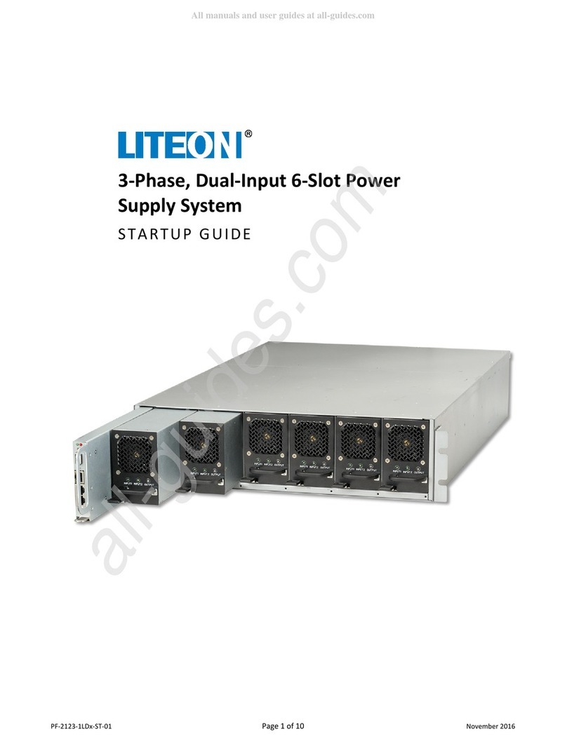
3-Phase, Dual-Input 6-Slot Power
Supply System
STARTUP GUIDE

STARTUP GUIDE
PF-2123-1LDx
6-Slot Power Supply System
PF-2123-1LDx-ST-01 Page 2 of 10 November 2016
© 2016 Copyright Lite-On Technology Corporation ALL RIGHTS RESERVED. Lite-On is a trademark of Lite-On Technology Corporation, registered in
the United States and other countries. This document may contain inaccuracies and typographical errors. Lite-On cannot be held responsible for
any errors or omissions contained in this document. All content is provided “As Is” and “As Available”. Lite-On reserves the right to correct errors
or omissions in this document. Other brand names mentioned herein are for identification purposes only and may be the trademarks of their
respective holder(s). Specifications and data are subject to change without notice.
Contents
Introduction...................................................................................................................................................... 3
General Safety Conventions ............................................................................................................................. 3
Safety and Regulatory Information .................................................................................................................. 3
Required Tools for Startup ............................................................................................................................... 5
Startup Checklist............................................................................................................................................... 5
Initial Power Activation .................................................................................................................................... 6
Shelf Power Activation...................................................................................................................................... 6
C13 Voltage Tests ............................................................................................................................................. 6
Installing Power Supply Units ........................................................................................................................... 7
PSU LED Status.................................................................................................................................................. 8
Related Documentation.................................................................................................................................... 9

STARTUP GUIDE
PF-2123-1LDx
6-Slot Power Supply System
PF-2123-1LDx-ST-01 Page 3 of 10 November 2016
Introduction
The 3-Phase, Dual-Input Power Supply System is a 6-slot chassis with 2.5KW Power Supply Units (PSUs)
that provides stable DC output power. This 19-inch power system uses up to 6 high-power, hot-swappable
PSUs for flexibility in full power or redundant operation.
There are two different models of the 6-Slot Power Supply System depending on input power
requirements as shown in the table below.
3-phase, Dual-Input Power Configuration
Model Number
EU Model, 346/ 360/ 380/ 400/ 415VAC PF-2123-1LDM
US Model, 200/ 208/ 220/ 230/ 240VAC PF-2123-1LDN
The 2.5kW PSUs efficiently supply both main output DC power and standby DC power from either AC or DC
sources. These compact PSUs provide 2.5kW, 12.5V / 200A power output and support PMBUS 1.2 with
boot loader, LED status indicators, and circuit protection features. For more information about the 2.5kW
PSU, refer to the Lite-On 2.5kW Dual-Input Power Supply Unit Datasheet.
This startup guide provides instructions to startup the 6-Slot Power Supply System for the first time. It
assumes that the 6-Slot Power Supply System has been properly installed and is ready for initial power up
and testing. Refer to Lite-On 3-Phase 12.5kW Power Supply System User Guide for installation instructions.
General Safety Conventions
This startup guide uses the safety conventions described below. Ensure that you follow the safety
instructions in this guide and observe its directives to protect you from injury and to protect your
equipment from damage.
WARNING
Indicates highly-dangerous consequences such as fire, serious injury, or death when
failing to comply with the instructions.
Caution
Indicates dangerous consequences such as moderate injury or equipment damage when
failing to comply with the instructions.
Safety and Regulatory Information
Caution
This product is for indoor use only.
Caution
Use proper fuses when wiring the equipment.
•Do not exceed the maximum output ratings as shown on the label.
•Do not use equipment over 50 °C ambient temperature.
•Do not exceed altitude of 3050 meters.
•Do not open the equipment to reduce the risk of electrical shock. For safety reasons it can only be
opened by qualified service personnel.

STARTUP GUIDE
PF-2123-1LDx
6-Slot Power Supply System
PF-2123-1LDx-ST-01 Page 4 of 10 November 2016
•Protect equipment objects falling through or liquids dripping into the openings. This could cause a
fire or electrical shock.
•Disconnect equipment from power supply before cleaning. Do not use any liquid or aerosol cleaner.
Use only moistened cloth.
•Equipment should be placed on a steady surface. A drop or fall could cause damages.
•The plug on the power supply cord is intended to serve as the disconnect device. It should be
installed near the equipment and should be easily accessible.
•The equipment is intended for installation in restricted access location where access is only
through the use of a special tool, lock, and key, or other means of security.
•If one of the following situations arise, check equipment by qualified service personnel
oInput connector is damaged.
oLiquid has penetrated into the equipment.
oEquipment has been exposed to humidity.
oEquipment has been dropped and/or is damaged.
oEquipment has obvious sign of breakage.
oEquipment does not work well or you cannot get it working according to user’s manual.
•The EUT overcurrent circuit protection relies on the final system, which includes a rated 60A circuit
breaker.
•Rack Mount Installation Precautions
oIf installed in a closed or multi-unit rack assembly, the operating ambient temperature of
the rack environment may be greater than room ambient. Therefore, consideration should
be given to installing the equipment in an environment compatible with the maximum
ambient temperature specified by the manufacturer.
oInstallation of the equipment in a rack should be such that the amount of air flow required
for safe operation of the equipment is not compromised.
oMounting of the equipment in the rack should be such that a hazardous condition is not
achieved due to uneven mechanical loading.
oConsideration should be given to the connection of the equipment to the supply circuit
and the effect that overloading of the circuits might have on overcurrent protection and
supply wiring. Appropriate consideration of equipment nameplate ratings should be used
when addressing this concern.
oEnsure that rack-mounted equipment is properly grounded. Particular attention should be
given to supply connections other than direct connections to the branch circuit.
•Ensure that PE wires being securely connected to the terminals before connecting AC input
cable(s).
•FCC declaration of conformity
oThis equipment has been tested and found to comply with the limits for a Class A digital
device, pursuant to Part 15 of the FCC Rules. These limits are designed to provide
reasonable protection against harmful interference when the equipment is operated in a
commercial environment. This equipment generates, uses, and can radiate radio
frequency energy and, if not installed and used in accordance with the instruction manual,
may cause harmful interference to radio communications. Operation of this equipment in
a residential area is likely to cause harmful interference, in which case the user will be
required to correct the interference at their own expense.
oThis device complies with Part 15 of the FCC rules. Operation is subject to the following
two conditions: (1) this device may not cause harmful interference, and (2) this device
must accept any interference received, including interference that may cause undesired
operation.

STARTUP GUIDE
PF-2123-1LDx
6-Slot Power Supply System
PF-2123-1LDx-ST-01 Page 5 of 10 November 2016
•Do not dispose of electrical appliances as unsorted municipal waste, use separate collection
facilities. Contact your local government for information regarding the collection systems
available.
Required Tools for Startup
Caution
There are NO USER SERVICEABLE PARTS inside the Power Shelf or Power Supply Units. All
repairs and service must be performed by AUTHORIZED SERVICE PERSONNEL only.
Warranty coverage will be void if unauthorized repair or service has been attempted.
Lite-On PSS shall not be liable for reimbursements, claims, damages, or injuries that may
result from the unauthorized repair of this product.
The following tools are required for initial startup of the 6-Slot Power Supply System.
•Digital Multimeter (DMM) for verifying power
Startup Checklist
Before activating power to the 6-Slot Power Supply System, verify that all conditions in the table below
have been met. At this point, the Power Shelf should be installed in the rack, power plugs connected, but
utility power not yet turned on. None of the Power Supply Units (PSUs), nor the optional Power Shelf
Controller, should be installed in the Power Shelf.
WARNING
To reduce the risk of fire, the unit connects only to a circuit provided with branch circuit
overcurrent protection in accordance with the National Electric Code, ANSI/NFPA 70. The
upstream circuit breaker must be easily accessible. The unit must be disconnected from
AC power source by opening this circuit breaker.
WARNING
Do not connect power to the Power Supply System until all conditions in the table below
have been successfully verified by qualified personnel who are knowledgeable with this
equipment and have proper electrical and mechanical expertise. Failure to meet all these
conditions could result in damage to the equipment or harm or death to personnel.
Conditions to be Met before Initial Startup
Yes?
No?
Is the rack properly installed, leveling feet down, and physically stable?
Are all rack screws and bolts tightened properly?
Is the rack properly grounded electrically?
Is the Power Shelf properly installed in the rack with its spring latches
connected to the rack so it cannot be pulled out?
Are all PSUs and the optional Power Shelf Controller removed from the Power
Shelf?
Are all Power Shelf linking bus bars properly installed and tightened?
Are all electrical cables the correct size?
Do all cable installations meet local electrical standards?
Are all power and control cables secured, routed, and properly terminated?
Are all electrical bolts and screws properly installed and tightened?
Does the power source meet electrical current and voltage requirements?

STARTUP GUIDE
PF-2123-1LDx
6-Slot Power Supply System
PF-2123-1LDx-ST-01 Page 6 of 10 November 2016
Conditions to be Met before Initial Startup
Yes?
No?
Is the Power Shelf properly connected to branch circuit overcurrent
protection in accordance with the National Electric Code, ANSI/NFPA 70?
Is the installation area dry and away from liquids?
Have all components to be installed been stored in a dry area?
Is the air temperature within normal operating range?
Is the area clean and free of debris and packing materials?
Are all people wearing proper protective equipment as defined by local
standards?
Do all people in the area know the location of emergency power-off switches,
fire extinguishers, and first aid equipment?
Initial Power Activation
After all conditions above have been met, power can be activated to the disconnected input power
connector and tested.
WARNING
To reduce the risk of fire, the unit connects only to a circuit provided with branch circuit
overcurrent protection in accordance with the National Electric Code, ANSI/NFPA 70. The
upstream circuit breaker must be easily accessible. The unit must be disconnected from
AC power source by opening this circuit breaker.
Caution
For Wye configurations, the voltage between the line to neutral connection should not
exceed 264VAC. If this voltage is exceeded, the PSUs will shut down and may cause PSU
damage.
Shelf Power Activation
To activate power to the Power Shelf:
1. Activate electrical power to the Power Shelf via its circuit breakers. The Power Shelf is activated
and ready for testing.
C13 Voltage Tests
The C13 receptacles in the Power Shelf are wired as described in the table below. Verify that the C13
receptacles have the correct voltage.
C13 Receptacles
(as viewed from rear of Power Shelf)
Model
Left C13 receptacles
PF-2123-1LDN; B (L2) – C (L3)
PF-2123-1LDM; C (L3) – N
Right C13 receptacles
PF-2123-1LDN; A (L1) –B (L2)
PF-2123-1LDM; A (L1) – N

STARTUP GUIDE
PF-2123-1LDx
6-Slot Power Supply System
PF-2123-1LDx-ST-01 Page 7 of 10 November 2016
To verify correct voltage on the C13 receptacles:
•With a DMM, verify that the C13 receptacles have power as described in the table above.
Installing Power Supply Units
After power has been activated and verified, PSUs can be installed into the Power Shelf. A PSU can be
plugged into any slot in the Power Shelf and they are keyed so they cannot be inserted incorrectly. At this
point, power should be activated and the output voltage will be tested after installing one of the PSUs. As
shown below, output voltage is tested at the rear of the Power Shelf.
To install and test Power Supply Units:
1. Activate power to both input power cables by turning on the circuit breaker for this power supply.
2. Slide a PSU into an empty slot in the front of the Power Shelf until it clicks into place. Both Input
lights on the PSU illuminate green to indicate that it is operational. If both lights do not illuminate
green on the PSU, contact Lite-On Power Systems technical support before proceeding.
3. Using a DMM, verify that the output voltage is 12.5VDC on the output connectors.
4. If the output voltage from the previous step is correct, slide the remaining PSUs into the empty
slots in the Power Shelf until they click into place. Both Input lights on all PSUs should illuminate
green.
5. Using a DMM, verify that the output voltage is still 12.5VDC.
C13 Receptacles C13 Receptacles
12.5 VDC Output

STARTUP GUIDE
PF-2123-1LDx
6-Slot Power Supply System
PF-2123-1LDx-ST-01 Page 8 of 10 November 2016
6. Turn on any connected devices to the Power Shelf and verify that the Power System is providing
power to the devices.
7. Refer to the Lite-On 3-Phase 12.5kW Power Supply System User Guide to install any other devices
to the Power System.
PSU LED Status
The following tables describe PSU LED status.
Input LEDs
INPUT1
INPUT2
AC_Normal
Solid Green
Solid Green
Vin_LOSS
Off
Off
Vin_OV_Fault
Off
Off
Vin_UV_Fault
Off
Off
Output LED
OUTPUT
Normal
Solid Green
Vout_OV_Warning
Blink Green
Vout_UV_Warning
Blink Green
Iout_OC_Warning
Blink Green
OT1_Warning
Blink Green
OT2_Warning
Blink Green
OT3_Warning
Blink Green
PSON
Blink Yellow
FAN_LOCK
Solid Yellow
OVP_SD
Solid Yellow
OCP_SD
Solid Yellow
OTP_SD
Solid Yellow
UV_SD
Solid Yellow
LATCH_SD
Solid Yellow
SCP_SD
Solid Yellow
STB_UVP
Solid Yellow
STB_OVP
Solid Yellow
STB_OCP
Solid Yellow
STB_OTP
Solid Yellow

STARTUP GUIDE
PF-2123-1LDx
6-Slot Power Supply System
PF-2123-1LDx-ST-01 Page 9 of 10 November 2016
Related Documentation
For information about the 12.5kW Power Shelf, refer to the Lite-On 12.5kW Power Shelf Datasheet.
For information about the 2.5kW Power Supply Unit, refer to the Lite-On 2.5kW Power Supply Unit
Datasheet.
For instructions on installing and using the 3-Phase 12.5kW Power Supply System, refer to the
Lite-On 3-Phase 12.5kW Power Supply System User Guide.
For more information related to the Lite-On Power Systems, visit the Lite-On Power Systems Solutions web
site at: http://www.liteon-pss.com.

STARTUP GUIDE
PF-2123-1LDx
6-Slot Power Supply System
Lite-On Power System Solutions
3001 Summit Ave, Suite 400
Plano, TX 75074
+1 (469) 331-9838
www.liteon-pss.com
email: [email protected]
Lite-On Power System Solutions
No. 90, Chien 1 Rd., Chung Ho Dist
New Taipei City 23585, Taiwan
+886 -2-2226181 ext 5026
www.liteon-pss.com
email: [email protected]
PF-2123-1LDx-ST-01 Page 10 of 10 November 2016
Innovative Power Management Solutions for Critical Infrastructure
Other manuals for PF-2123-1LDM
1
This manual suits for next models
1
Table of contents
Other LiteOn Power Supply manuals