LiteOn PF-2123-2 User guide

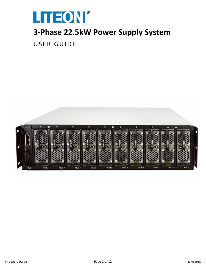
3-Phase, 10-Slot Power Supply System
STARTUP GUIDE
PF-2223-1-ST-02 Page 1 of 10 July 2015

STARTUP GUIDE
PF-2123-2, PF-2223-1
10-Slot Power Supply System
PF-2223-1-ST-02 Page 2 of 10 July 2015
© 2015 Copyright Lite-On Technology Corporation ALL RIGHTS RESERVED. Lite-On is a trademark of Lite-On Technology Corporation, registered in
the United States and other countries. This document may contain inaccuracies and typographical errors. Lite-On cannot be held responsible for
any errors or omissions contained in this document. All content is provided “As Is” and “As Available”. Lite-On reserves the right to correct errors
or omissions in this document. Other brand names mentioned herein are for identification purposes only and may be the trademarks of their
respective holder(s). Specifications and data are subject to change without notice.
Contents
Introduction...................................................................................................................................................... 3
General Safety .................................................................................................................................................. 3
Required Tools for Startup ............................................................................................................................... 4
Startup Checklist............................................................................................................................................... 4
Initial Power Activation .................................................................................................................................... 5
Shelf Power Activation...................................................................................................................................... 7
C13 Voltage Tests ............................................................................................................................................. 7
Installing Power Supply Units ........................................................................................................................... 8
Related Documentation.................................................................................................................................... 9

STARTUP GUIDE
PF-2123-2, PF-2223-1
10-Slot Power Supply System
PF-2223-1-ST-02 Page 3 of 10 July 2015
Introduction
The 3-Phase Power Supply System is a 10-slot chassis with 2.5KW Power Supply Units (PSUs) that provides
stable DC output power. This 21-inch power system uses up to 10 high-power, hot-swappable PSUs for
flexibility in full power or redundant operation.
There are different models of the 10-Slot Power Supply System depending on output power requirements
and input power configuration as shown in the table below.
3-phase Input Power Configuration
Model Number
Line-to-Line 4-Wire System
PF-2223-1L1N – 10 slot single input
PF-2123-2LNN – 5+5 slot single input
PF-2223-1LDN – 10 slot dual input
Line-to-Neutral 5-Wire System
PF-2223-1L1M – 10 slot single input
PF-2123-2LNM – 5+5 slot single input
PF-2223-1LDM – 10 slot dual input
The 2.5kW PSUs efficiently supply both main output DC power and standby DC power from either AC or DC
sources. These compact PSUs provide 2.5kW, 12.5V / 200A for main power output and 30W, 12V / 2.5A for
standby power applications. In addition, they support PMBUS 1.2 with boot loader, LED status indicators,
and circuit protection features. For more information about the 2.5kW PSU, refer to the Lite-On 2.5kW
Power Supply Unit Datasheet.
This startup guide provides instructions to startup the 10-Slot Power Supply System for the first time. It
assumes that the 10-Slot Power Supply System has been properly installed and is ready for initial power up
and testing. Refer to Lite-On 3-Phase 22.5kW Power Supply System User Guide for installation instructions.
General Safety
This startup guide uses the safety conventions described below. Ensure that you follow the safety
instructions in this guide and observe its directives to protect you from injury and to protect your
equipment from damage.
WARNING
Indicates highly-dangerous consequences such as fire, serious injury, or death when
failing to comply with the instructions.
Caution
Indicates dangerous consequences such as moderate injury or equipment damage when
failing to comply with the instructions.

STARTUP GUIDE
PF-2123-2, PF-2223-1
10-Slot Power Supply System
PF-2223-1-ST-02 Page 4 of 10 July 2015
Required Tools for Startup
Caution
There are NO USER SERVICEABLE PARTS inside the Power Shelf or Power Supply Units. All
repairs and service must be performed by AUTHORIZED SERVICE PERSONNEL only.
Warranty coverage will be void if unauthorized repair or service has been attempted.
Lite-On PSS shall not be liable for reimbursements, claims, damages, or injuries that may
result from the unauthorized repair of this product.
The following tools are required for initial startup of the 10-Slot Power Supply System.
•Digital Multimeter (DMM) for verifying power
•T-20 star driver for input power connector
•Torque driver to tighten connectors and cables
Startup Checklist
Before activating power to the 10-Slot Power Supply System, verify that all conditions in the table below
have been met. At this point, the Power Shelf should be installed in the rack, but power not yet turned on.
None of the Power Supply Units (PSUs), nor the optional Shelf Controller, should be installed in the Power
Shelf.
WARNING
To reduce the risk of fire, the unit connects only to a circuit provided with branch circuit
overcurrent protection in accordance with the National Electric Code, ANSI/NFPA 70. The
upstream circuit breaker must be easily accessible. The unit must be disconnected from
AC power source by opening this circuit breaker.
WARNING
Do not connect power to the 22.5kW Power System until all conditions in the table below
have been successfully verified by qualified personnel who are knowledgeable with this
equipment and have proper electrical and mechanical expertise. Failure to meet all these
conditions could result in damage to the equipment or harm or death to personnel.
Conditions to be Met before Initial Startup
Yes?
No?
Is the rack properly installed, leveling feet down, and physically stable?
Are all rack screws and bolts tightened properly?
Is the rack properly grounded electrically?
Is the Power Shelf properly installed in the rack with its spring latches
connected to the rack so it cannot be pulled out?
Are all PSUs and the optional Shelf Controller removed from the Power Shelf?
Are all Power Shelf linking busbars properly installed and tightened?
Are all electrical cables the correct size?
Do all cable installations meet local electrical standards?
Are all power and control cables secured, routed, and properly terminated?
Are all electrical bolts and screws properly installed and tightened?
Does the power source meet electrical current and voltage requirements?
Is the Power Shelf properly connected to branch circuit overcurrent
protection in accordance with the National Electric Code, ANSI/NFPA 70?
Is the installation area dry and away from liquids?

STARTUP GUIDE
PF-2123-2, PF-2223-1
10-Slot Power Supply System
PF-2223-1-ST-02 Page 5 of 10 July 2015
Conditions to be Met before Initial Startup
Yes?
No?
Have all components to be installed been stored in a dry area?
Is the air temperature within normal operating range?
Is the area clean and free of debris and packing materials?
Are all people wearing proper protective equipment as defined by local
standards?
Do all people in the area know the location of emergency power-off switches,
fire extinguishers, and first aid equipment?
Initial Power Activation
After all conditions above have been met, power can be activated to the disconnected input power
connector and tested.
WARNING
To reduce the risk of fire, the unit connects only to a circuit provided with branch circuit
overcurrent protection in accordance with the National Electric Code, ANSI/NFPA 70. The
upstream circuit breaker must be easily accessible. The unit must be disconnected from
AC power source by opening this circuit breaker.
Caution
For Wye configurations, the voltage between line to neutral connection should not
exceed 264VAC. If this voltage is exceeded, the PSUs will shut down and may cause PSU
damage.
To test power to the input power connector:
1. Activate power to a properly-wired, but disconnected, input power connector by turning on its
upstream circuit breaker.
2. Using a DMM, verify that legs L1–L2, L2–L3, L3–L1, N (neutral), L1–N, L2–N, L3–N, and FG (frame
ground) have the expected voltage according to the 3-phase electrical configuration (4-wire or 5-
wire connection) and voltage of your system. Refer to the input power connector pinout graphic
and wiring tables below.

STARTUP GUIDE
PF-2123-2, PF-2223-1
10-Slot Power Supply System
PF-2223-1-ST-02 Page 6 of 10 July 2015
L1
AC Input L1 (R)
L2
AC Input L2 (S)
L3
AC Input L3 (T)
N
Neutral
FG
Frame Ground
3-Phase, 5-Wire System (with neutral)
PF-2223-1L1M – 10 slot single input
PF-2123-2LNM – 5+5 slot single input
PF-2223-1LDM – 10 slot dual input
L1–L2 L2–L3 L3–L1
380VAC 380VAC 380VAC 380VAC
400VAC 400VAC 400VAC 400VAC
415VAC 415VAC 415VAC 415VAC
PF-2223-1L1M – 10 slot single input
PF-2123-2LNM – 5+5 slot single input
PF-2223-1LDM – 10 slot dual input
L1–N L2–N L3–N
380 VAC 220 VAC 220 VAC 220 VAC
400 VAC 230 VAC 230 VAC 230 VAC
415 VAC 240 VAC 240 VAC 240 VAC
Input Power Connector
Pinout

STARTUP GUIDE
PF-2123-2, PF-2223-1
10-Slot Power Supply System
PF-2223-1-ST-02 Page 7 of 10 July 2015
3-Phase, 4-Wire System (without neutral)
PF-2223-1L1N – 10 slot single input
PF-2123-2LNN – 5+5 slot single input
PF-2223-1LDN – 10 slot dual input
L1–L2 L2–L3 L3–L1
208VAC 208VAC 208VAC 208VAC
220VAC 220VAC 220VAC 220VAC
230VAC 230VAC 230VAC 230VAC
240VAC 240VAC 240VAC 240VAC
3. After verifying the input power connector has been wired correctly, disconnect power from the
connector by turning off its upstream circuit breaker.
Shelf Power Activation
After the wiring to the input power connector has been tested and verified, it can be plugged into and
secured to the Power Shelf.
To secure the input power connector and activate the Power Shelf:
1. Using a DMM, verify that power is disconnected from the input power connector.
2. Insert the wired connector into the input connector of the Power Shelf and secure the connector
in place by torqueing the screws to 4 N-m (3.0 ft-lbs) with a T-20 star driver.
3. Activate electrical power to the Power Shelf via its circuit breakers. The Power Shelf is activated
and ready for testing.
C13 Voltage Tests
Verify that the Power Shelf has the correct voltage on the C13 receptacles as shown in the table below.
C13 Receptacles
(as viewed from rear of Power Shelf)
Phase A Input Power
Left three C13 receptacles (same voltage as Phase A)
Phase B Input Power
None
Phase C Input Power
Right three C13 receptacles (same voltage as Phase C)
To verify correct voltage on the C13 receptacles:
•With a DMM, verify that the C13 receptacles have power. As shown below, Phase A (L1) power
should be available on the left side C13 receptacles and Phase C (L3) power should be available on
the right side C13 receptacles.

STARTUP GUIDE
PF-2123-2, PF-2223-1
10-Slot Power Supply System
PF-2223-1-ST-02 Page 8 of 10 July 2015
Installing Power Supply Units
After power has been activated and verified, PSUs can be installed into the Power Shelf. A PSU can be
plugged into any slot in the Power Shelf and they are keyed so they cannot be inserted incorrectly. At this
point, power should be activated and the output voltage will be tested after installing one of the PSUs. As
shown below, output voltage is tested at the rear of the Power Shelf.
To install and test Power Supply Units:
1. Slide a PSU into an empty slot in the front of the Power Shelf until it clicks into place. Both lights on
the PSU illuminate green to indicate that it is operational. If both lights do not illuminate green on
the PSU, contact Lite-On Power Systems technical support before proceeding.
2. Using a DMM, verify that the output voltage is 12.5VDC on all three output connectors. Note: the
output connectors are on the same bus so the voltage should be the same on all three connectors.
3. If the output voltage from the previous step is correct, slide the remaining PSUs into the empty
slots in the Power Shelf until they click into place. Both lights on all PSUs should illuminate green.
4. Using a DMM, verify that the output voltage is still 12.5VDC.
5. Turn on any connected devices to the Power Shelf and verify that the Power System is providing
power to the devices.
6. Refer to the Lite-On 3-Phase 22.5kW Power Supply System User Guide to install any other devices
to the Power System.
C13 Receptacles Phase A
C13 Receptacles Phase C
12.5 VDC Output
12.5 VDC Output
12.5 VDC Output

STARTUP GUIDE
PF-2123-2, PF-2223-1
10-Slot Power Supply System
PF-2223-1-ST-02 Page 9 of 10 July 2015
Related Documentation
For information about the 22.5kW Power Shelf, refer to the Lite-On 22.5kW Power Shelf Datasheet.
For information about the 2.5kW Power Supply Unit, refer to the Lite-On 2.5kW Power Supply Unit
Datasheet.
For instructions on installing and using the 3-Phase 22.5kW Power Supply System, refer to the
Lite-On 3-Phase 22.5kW Power Supply System User Guide.
For more information related to the Lite-On Power Systems, visit the Lite-On Power Systems Solutions web
site at: http://www.liteon-pss.com.

STARTUP GUIDE
PF-2123-2, PF-2223-1
10-Slot Power Supply System
Lite-On Power System Solutions
3001 Summit Ave, Suite 400
Plano, TX 75074
+1 (469) 331-9838
www.liteon-pss.com
email: [email protected]
Lite-On Power System Solutions
No. 90, Chien 1 Rd., Chung Ho Dist
New Taipei City 23585, Taiwan
+886 -2-2226181 ext 5026
www.liteon-pss.com
email: [email protected]
PF-2223-1-ST-02 Page 10 of 10 July 2015
Innovative Power Management Solutions for Critical Infrastructure
This manual suits for next models
1
Table of contents
Other LiteOn Power Supply manuals