LiteOn VPOC VP-3103-111U User manual

VP-3103-111U-UG-03 Page 1 of 23 September 2016
10kW VPOC™ Power System
USER GUIDE

USER GUIDE
VP-3103-111U
10kW VPOC™ Power System
VP-3103-111U-UG-03 Page 2 of 23 September 2016
© 2015 Copyright Lite-On Technology Corporation ALL RIGHTS RESERVED. Lite-On is a trademark of Lite-On Technology Corporation, registered in
the United States and other countries. This document may contain inaccuracies and typographical errors. Lite-On cannot be held responsible for
any errors or omissions contained in this document. All content is provided “As Is” and “As Available”. Lite-On reserves the right to correct errors
or omissions in this document. Other brand names mentioned herein are for identification purposes only and may be the trademarks of their
respective holder (s). Specifications and data are subject to change without notice.
Contents
Introduction...................................................................................................................................................... 3
General Safety Conventions ............................................................................................................................. 3
Safety Cautions and Warnings.......................................................................................................................... 3
Required Tools for Installation and Maintenance ............................................................................................ 4
Unpacking and Checklist................................................................................................................................... 4
Equipment Inspection....................................................................................................................................... 5
VPOC™ Power System and Rack Preparations ................................................................................................. 5
Rack Mounting Brackets Installation ......................................................................................................... 5
Shelf Support Brackets Installation ............................................................................................................ 5
VPOC™ Power Shelf Installation ....................................................................................................................... 6
Remote Emergency Power Off Configuration .................................................................................................. 9
NC (normally closed) Configuration – REPO triggered by opening a switch............................................ 10
NO (normally open) Configuration – REPO triggered by closing a switch ............................................... 10
VPOC™ Power Module Installation ................................................................................................................ 10
PDU Installation .............................................................................................................................................. 15
VPOC™ Lithium Ion Battery Module Installation............................................................................................ 16
VRLA Battery Installation ................................................................................................................................ 17
VPOC™ Power System Startup ....................................................................................................................... 18
VPOC™ Power Shelf Front Panel Controls and Lights..................................................................................... 19
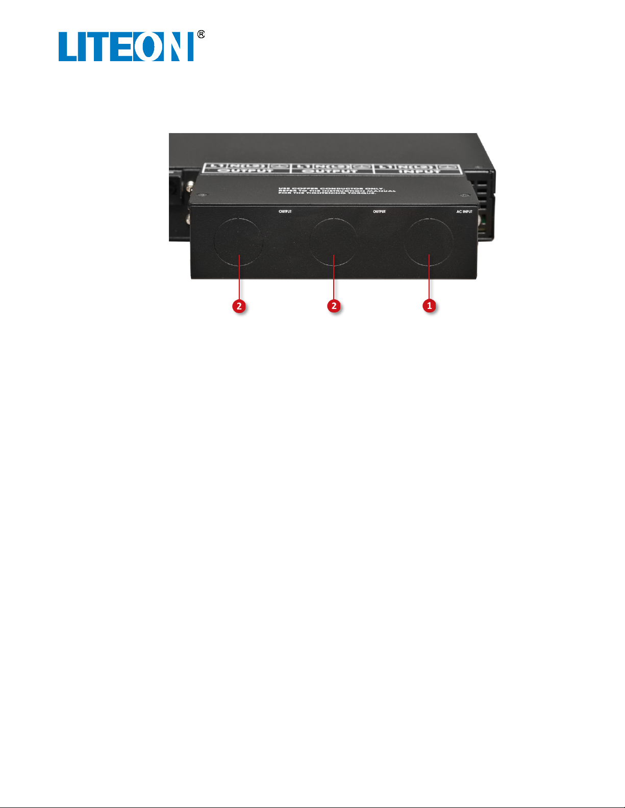
VPOC™ Rear Panel .......................................................................................................................................... 20
Dry Contact Configuration .............................................................................................................................. 21
Warranty......................................................................................................................................................... 21
Related Documentation.................................................................................................................................. 22

USER GUIDE
VP-3103-111U
10kW VPOC™ Power System
VP-3103-111U-UG-03 Page 3 of 23 September 2016
Introduction
Virtual Power On Call (VPOC™) is a highly-efficient backup power solution that uses a fraction of the space
of a conventional Uninterruptable Power System (UPS). The 10kW VPOC™ module, along with two Lithium
Ion (Li-ion) battery modules, slides into the 1U VPOC™ Shelf. VPOC automatically manages transitions
between normal (AC) operation and battery mode (DC) to keep IT equipment safe during power
interruptions. An external VRLA battery solution may be substituted for Li-ion batteries for even longer
backup times. For more information about the 10kW VPOC™ Power Shelf, refer to the Lite-On 10kW
VPOC™ Power Shelf Datasheet.
The 10kW Power Module efficiently supplies both main output DC power and standby DC power from
either AC or DC sources. For more information about the 10kW VPOC™ Power Module, refer to the Lite-On
10kW VPOC™ Power Module Datasheet.
This user guide provides instructions to install and use the 10kW VPOC™ Power System. For instructions on
initial startup, refer to the Lite-On VPOC™ System Startup Guide.
General Safety Conventions
This user guide uses the safety conventions described below. Ensure that you follow the safety instructions
in this guide and observe its directives to protect you from injury and to protect your equipment from
damage.
WARNING
Indicates highly-dangerous consequences such as fire, serious injury, or death when
failing to comply with the instructions.
Caution
Indicates dangerous consequences such as moderate injury or equipment damage when
failing to comply with the instructions.
Safety Cautions and Warnings
WARNING
The VPOC™ system is a high-voltage DC power source when batteries are installed or
when it is connected to external batteries. Terminals may be energized even if the system
is disconnected from AC power source.
Caution
Batteries should only be serviced by personnel knowledgeable with VPOC™ system
batteries. Keep unauthorized personnel away from batteries. Properly dispose used
batteries; refer to your local laws and regulations for disposal requirements.
Caution
Ensure that the VPOC™ system is properly grounded at all times.
Caution
Do not block or insert any object into ventilation holes.

USER GUIDE
VP-3103-111U
10kW VPOC™ Power System
VP-3103-111U-UG-03 Page 4 of 23 September 2016
WARNING
Turn off the VPOC™ system before cleaning it. Use a soft cloth to clean it, never use
liquid, or aerosol cleaners.
WARNING
Do not install the VPOC™ system near liquids or in a damp environment.
Caution
Do not expose the VPOC™ system to direct sunlight or a source of heat.
Caution
If the VPOC™ system must be stored prior to installation, store in a dry place.
Required Tools for Installation and Maintenance
The following tools are required for installing and maintaining the Power System.
•#2 and #3 Phillips screwdrivers
•Flat blade screwdriver
•Torque driver to tighten connectors and cables
•Digital Multimeter (DMM) for testing and verifying power
Unpacking and Checklist
Carefully unpack the rack (if applicable), VPOC™ Power Shelf, VPOC™ Power Module, and batteries. Move
all components to the staging area for assembly. It is recommended that you keep the packaging in case
equipment needs to be returned to the supplier.
The following tools may be required for unpacking.
•Screwdriver for removing screws from rack packaging
•Wrench for removing bolts from rack packaging
•Crowbar for opening wooden boxes (if nailed)
•Box cutter or utility knife for opening cardboard packaging
WARNING
A least two people are required to remove the rack from its shipping container to ensure
that the rack stays upright and does not fall on personnel.
To unpack the rack from its shipping crate:
1. Remove the front panel from the shipping crate.
2. Remove any shipping bolts from the rack that hold the rack to the crate.
3. If necessary, remove any shipping blocks or straps from around the rack.
4. If necessary, raise the leveling feet to their highest position.
5. Secure a ramp to the front of the crate.
6. Using two or more people, carefully roll the rack out of the crate and down the ramp.
7. Inspect the rack to ensure that it was not damaged during shipping.
To unpack items from cardboard shipping boxes:
1. If necessary, remove any shipping straps from around the box.

USER GUIDE
VP-3103-111U
10kW VPOC™ Power System
VP-3103-111U-UG-03 Page 5 of 23 September 2016
2. Place the box upright and cut through the tape on the top of the box.
3. Remove the item(s) from the box along with any shipping foam if necessary.
4. Remove the item(s) from any shipping foam or wrapping material.
After all items have been unpacked, verify that you have received all the items as specified by the shipping
paperwork.
Equipment Inspection
After unpacking the equipment, inspect it for damage that might have resulted from shipment. Check for
the items below and contact the shipper in the unlikely event that damage is found.
•Bent connectors, alignment pins, or chassis
•Any cracks or chips on plastic components
•Unusual scratches or marks
•Dents in sheet metal or panels
•Corrosion or evidence of water or chemical damage
•Indications that the device was dropped
•Loose parts inside the equipment
VPOC™ Power System and Rack Preparations
These instructions assume that the rack has been moved into place and is installed properly.
The VPOC™ Power Shelf slides into a 19-inch rack and is supported in the rack by shelf support brackets. If
the Shelf Support Brackets are not already installed in the rack, follow instructions
Rack Mounting Brackets Installation
The VPOC™ Power Shelf, PDU, and VRLA battery are secured to the rack by supplied rack mounting
brackets.
To Install Rack Mounting Brackets:
1. Remove rack mounting brackets and screws from the device packing box.
2. Install the left and right rack mounting brackets with the supplied screws.
3. Torque all rack mounting bracket screws to 0.8N-m (0.6 ft-lbs).
Shelf Support Brackets Installation
The weight of the VPOC™ Power Shelf and VRLA battery are supported in the rack by two Shelf Support
Brackets. Each bracket is held in place by four M6 x 12mm self-threading screws.
To Install the Shelf Support Brackets:
1. Place a Shelf Support Bracket in the correct position in the rack and loosely attach it to the shelf
with four M6 screws.
2. Place the other Shelf Support Bracket in the correct position in the rack and loosely attach it to the
shelf with four M6 screws.
3. Torque all Shelf Support Bracket screws to 6.1 N-m (4.5 ft-lbs).

USER GUIDE
VP-3103-111U
10kW VPOC™ Power System
VP-3103-111U-UG-03 Page 6 of 23 September 2016
VPOC™ Power Shelf Installation
After the Rack Mounting Brackets have been installed on the VPOC™ Power Shelf and the Shelf Support
Brackets have been installed into the rack, the VPOC™ Power Shelf can be installed into the rack.
WARNING
To prevent risk of electrical shock to personnel, ensure that power is not activated inside
the rack while installing equipment. Use a DMM to test any potentially live wires and
verify that electrical power is turned off to the rack.
WARNING
To prevent risk of electrical shock to personnel, ensure that all installation and repairs are
performed by AUTHORIZED SERVICE PERSONNEL ONLY.
The VPOC™ Power Shelf wiring and power requirements are listed below:
•Connect to branch circuit overcurrent protection in accordance with the National Electric Code,
ANSI/NFPA 70 and in accordance with local electrical standards
•Use an external input circuit breaker: 80 amps / 2-pole
•Use conduit or raceway to connect wiring from the VPOC™ Power Shelf to the building
•Use copper wire 60°C / #6 AWG
To Install the VPOC™ Power Shelf into the Rack:
1. If VPOC™ Lithium-Ion Battery Modules are going to be used in this installation, remove both
Lithium-Ion Battery Module cover plates by removing the cover plate screws on the bottom of the
VPOC™ Power Shelf (see ❶below) and removing the cover plates (see ❷below).
❶Lithium-Ion battery module cover plate screws (two screws for each plate)
❷Lithium-Ion battery module cover plate
2. Carefully lift the VPOC™ Power Shelf and move it into the rack on top of the Shelf Support
Brackets.
3. Push the VPOC™ Power Shelf into the rack until the Rack Mounting Brackets align with the rack
and loosely attach it to the shelf with four M6 screws.
4. Torque all M6 screws to 6.1 N-m (4.5 ft-lbs).

USER GUIDE
VP-3103-111U
10kW VPOC™ Power System
VP-3103-111U-UG-03 Page 7 of 23 September 2016
5. On the rear side of the VPOC™ Power Shelf, twist out the AC input knockout plugs (see ❶below)
and 1 or 2 output knockout plugs (see ❷below) as required by your output power requirements.
6. On the rear side of the VPOC™ Power Shelf, remove two cover screws (see ❶below) and remove
the wiring protective cover (see ❷below).
7. Install supplied cable glands as shown below. One cable gland is supplied with the VPOC™ Power
Shelf and one cable gland is supplied for each PDU.
8. Unscrew the cable glands so wires can be fed through them (see ❸and ❹below).
9. Ensure that the VPOC™ Power Shelf input switch (see ❺below) is in the OFF position.

USER GUIDE
VP-3103-111U
10kW VPOC™ Power System
VP-3103-111U-UG-03 Page 8 of 23 September 2016
❶Protective wiring cover screws
❷Protective wiring cover
❸Input wiring port
❹Output wiring ports
❺AC Power input switch
❻Remote Emergency Power Off connector
WARNING
To prevent risk of electrical shock to personnel, ensure that power is not activated when
wiring the VPOC™ Power Shelf. Use a DMM to test any potentially live wires and verify
that electrical power is turned off.
10. As shown below, install the input and output wires through the cable glands according to the
wiring diagram on the VPOC™ Power Shelf and in accordance with local wiring standards. The use
of electrical wiring ferrules are recommended on the wires that are attached to the VPOC™ Power
Shelf. PDUs are connected directly to the VPOC™ Power Shelf; the PDU Installation section (later in
this guide) provides for instructions on mounting PDUs to the rack.

USER GUIDE
VP-3103-111U
10kW VPOC™ Power System
VP-3103-111U-UG-03 Page 9 of 23 September 2016
11. Torque the wiring set screws to 1.5 N-m (1.2 ft-lbs).
12. Replace the protective wiring cover and secure with previously-removed cover screws.
13. Tighten the cable glands to secure input and out wiring.
14. If Remote Emergency Power Off (REPO) is used, wire the EPO connector as described in the section
below.
Remote Emergency Power Off Configuration
The VPOC™ Power Shelf supports normally closed or normally opened Remote Emergency Power Off
(REPO) settings. If necessary, wire REPO according to your system requirements. If REPO is not used,
ensure that a jumper wire shorts across pins 1 and 2 on the Remote Emergency Power Connector to
prevent VPOC™ Power System shutdown.
To insert or remove a wire from the REPO connector, push in and hold the orange tab above the connector
while inserting or removing a wire.
Remote Emergency Power Off Connector
Position
Description
Pins 1 and 2
A REPO will trigger when pins 1 and 2 along with pins 3 and 4 are in the same
condition, either both sets open or both sets closed. This provides the flexibility to
choose an EPO condition with a normally-closed or open configuration.
Pins 3 and 4

USER GUIDE
VP-3103-111U
10kW VPOC™ Power System
VP-3103-111U-UG-03 Page 10 of 23 September 2016
NC (normally closed) Configuration – REPO triggered by opening a switch
The left graphic below shows an “energized” VPOC™ in the normally closed (NC) configuration. Pins 1 and
2 are closed, and pins 3 and 4 are open. If pins 1 and 2 open, as shown in the right graphic below, a REPO
event is triggered.
Energized VPOC™
Normally Closed REPO-Triggered Event
NO (normally open) Configuration – REPO triggered by closing a switch
The left graphic below shows an “energized” VPOC™ in the normally open (NO) configuration. Pins 1 and 2
are closed, and pins 3 and 4 are open. If pins 3 and 4 close, as shown in the right graphic below, a REPO
event is triggered.
Energized VPOC™
Normally Open REPO-Triggered Event
VPOC™ Power Module Installation
The VPOC™ Power Shelf ships without any installed modules; they can be installed after the shelf is
installed into the rack. The 10kW VPOC™ Power Module slides into the front of the VPOC™ Power Shelf.
After the VPOC™ Power Module is installed, its ribbon cable is connected to the VPOC™ Power Shelf bezel.
WARNING
To prevent risk of electrical shock to personnel, ensure that the VPOC™ Power Shelf is
empty and does not contain VPOC™ Lithium Ion Battery Modules. If batteries are
installed, terminal blocks may be energized even if the system is disconnected from the
AC power source.

USER GUIDE
VP-3103-111U
10kW VPOC™ Power System
VP-3103-111U-UG-03 Page 11 of 23 September 2016
To install the VPOC™ Power Module:
1. Remove the bezel from the front of the VPOC™ Power Shelf by pressing in the tabs on each side of
the bezel and pulling out the bezel (see ❶below).
2. Remove two screws holding the cable locking bracket (see ❶below) and remove the cable
locking bracket (see ❷below).

USER GUIDE
VP-3103-111U
10kW VPOC™ Power System
VP-3103-111U-UG-03 Page 12 of 23 September 2016
3. Pull out the locking handle of the VPOC™ Power Module (see ❶below) and insert the module
into the left-most slot labeled PWR MODULE as shown below. Put your thumb under the locking
handle when pushing it in; as module engages the chassis, the locking handle will move up slightly.
4. Complete module installation by pushing up the locking handle until it locks into place into the
chassis.
5. Connect cable from the front bezel to the VPOC™ Power Module (see ❶below) until it latches
into place. Note: You must press down this latch to separate this connector when removing the
Power Module from the bezel.

USER GUIDE
VP-3103-111U
10kW VPOC™ Power System
VP-3103-111U-UG-03 Page 15 of 23 September 2016
8. Secure cable to chassis with cable locking bracket and two screws that were removed in a previous
step (see ❶below).
9. Push the bezel back onto the front of the VPOC™ Power Shelf until the tabs lock into place (see ❶
below).
PDU Installation
Power Distribution Units (PDUs) distribute output power from the VPOC™ Power Shelf to rack-mounted
equipment. A PDU can be mounted horizontally or vertically in the front or rear of a rack. When power is
activated to a PDU, an indicator light illuminates.
WARNING
To prevent risk of electrical shock to personnel, ensure that power is not activated inside
the rack while installing equipment. Use a DMM to test any potentially live wires and
verify that electrical power is turned off to the rack.

USER GUIDE
VP-3103-111U
10kW VPOC™ Power System
VP-3103-111U-UG-03 Page 16 of 23 September 2016
To install a PDU to a rack:
1. Using the supplied M3 screws, install rack mounting brackets on the PDU in accordance to your
mounting requirements so the brackets align with the holes on the rack. The rack mounting
brackets can be mounted so the tabs are flush to the front of the PDU or flush to the rear of the
PDU.
2. Torque the rack mounting bracket M3 screws to 0.6 N-m (0.45ft-lbs).
3. If not already connected, wire the PDU to the VPOC™ Power Shelf or distribution unit according to
your electrical requirements.
4. Install the PDU to the rack and loosely attach it with four M6 screws.
5. Torque all M6 screws to 6.1 N-m (4.5 ft-lbs).
VPOC™ Lithium Ion Battery Module Installation
The VPOC™ Power System supports either lithium-ion batteries or VRLA batteries.
Caution
To prevent damage to the VPOC™ Power System, ensure that it is powered off before
adding or removing lithium-ion batteries.
To add Lithium Ion Battery Modules to the VPOC™ Power System:
1. Remove the bezel from the front of the VPOC™ Power Shelf by pressing in the tabs on each side of
the bezel and pulling out the bezel (see ❶below).
2. Ensure that the Lithium Ion Battery Module plates have already been removed as described in the
VPOC™ Power Shelf Installation section.
3. Slide the Lithium Ion Battery Modules into the battery module slots (labeled BAT MODULE) in the
VPOC™ Power Shelf.
4. Push the bezel back onto the front of the VPOC™ Power Shelf until the tabs lock into place (see ❶
below).

USER GUIDE
VP-3103-111U
10kW VPOC™ Power System
VP-3103-111U-UG-03 Page 17 of 23 September 2016
VRLA Battery Installation
After the VRLA Battery Shelf Support Brackets are installed into the rack, it can be installed into the rack.
WARNING
To prevent risk of electrical shock to personnel, ensure that power is not activated inside
the rack while installing equipment. Use a DMM to test any potentially live wires and
verify that electrical power is turned off to the rack.
WARNING
To prevent risk of electrical shock to personnel, ensure that the breaker on the VRLA
Battery Shelf is switched to OFF when connecting or disconnecting it to the VPOC™ Power
Shelf or connecting to other VRLA Battery Shelves.
Caution
The VRLA Battery shelf weighs more than 140 pounds. Use two or more people to move
the VRLA Battery shelf and install it into the rack.
Caution
Only use the supplied electrical cable that ships with the VRLA Battery shelf to connect a
VPOC™ Power Shelf to a VRLA Battery shelf.
To Install the VRLA Battery Shelf into the Rack:
1. Carefully lift the VRLA Battery Shelf and move it into the rack on top of the Shelf Support Brackets.
2. If necessary, installed VRLA Battery Shelf rack mounting brackets.
3. Torque the rack mounting bracket screws to 0.6 N-m (0.45ft-lbs).
4. Push the VRLA Battery Shelf into the rack until the rack mounting brackets align with the rack.
5. Install the PDU to the rack and loosely attach it with four M6 screws.
6. Torque all M6 screws to 6.1 N-m (4.5 ft-lbs).
7. Connect the supplied electrical cable from the back of the VPOC™ Power Shelf (see ❶below) to
either the top or bottom VRLA Battery Shelf power port (see ❷and ❸below).

USER GUIDE
VP-3103-111U
10kW VPOC™ Power System
VP-3103-111U-UG-03 Page 18 of 23 September 2016
❶VPOC™ Power Shelf VRLA battery connector
❷VRLA Battery Shelf battery connector
❸VRLA Battery Shelf battery connector
Note: multiple VRLA Battery Shelves can be connected to the VPOC™ Power Shelf to extend runtime. To
connect another VRLA Battery Shelf, install it close to an existing VRLA Battery Shelf and install the
supplied electrical cable between the batteries (see ❷and ❸above).
VPOC™ Power System Startup
Refer to the 10kW VPOC™ Power System Startup Guide for startup instructions.

USER GUIDE
VP-3103-111U
10kW VPOC™ Power System
VP-3103-111U-UG-03 Page 19 of 23 September 2016
VPOC™ Power Shelf Front Panel Controls and Lights
Refer to the graphic and table below for an explanation of the buttons and lights located on the VPOC™
Power Shelf front panel.
Alarm Silence /
Manual Battery Test
Button
Press for 1 second to silence a connected alarm. After the alarm is
silenced, the alarm system is reactivated.
For VRLA batteries only: Press for 1 second during normal operation to
initiate VRLA battery test. Press for 1 second to end battery test.
For Li-ion batteries only: Press for 1 second during normal operation to
electrically disconnect Li-ion battery from the VPOC™ Power System.
Press for 1 second to reconnect to Li-ion battery.
On / Standby /
Manual Bypass
Button
For VRLA batteries only without AC input: Press and hold for 4 seconds
to cold start VPOC™ operation.
Press and hold for 4 seconds when operating in AC mode activates
internal automatic bypass mode.
When in internal automatic bypass mode, press twice within 4 seconds
to turn off all VPOC™ output capability. Ensure that the shelf
maintenance bypass switch is engaged to maintain power to the load.
Load Level Indicators
Displays approximate load in 20% increments of full load. The 100%
column flashes when operating in an overload condition.
Battery Level
Indicators
Displays remaining capacity in 20% increments. The 100% column
flashes when batteries are charging.
AC Output Indicator
(Green)
On: normal mode — AC out
Off: output determined by operating conditions
Bypass Indicator
(Amber)
On: operating with internal bypass — AC out
Off: output determined by operating conditions
Fault Indicator (Red)
On: a fault condition exists
Off: no faults detected
AC Input Indicator
(Green)
On: AC input is within allowed range
Off: no AC input
Flashing: AC input is outside allowed range
Battery Indicator
(Amber)
On: operating in Battery mode – DC out
Off: output determined by operating conditions
Flashing: Battery source not available

USER GUIDE
VP-3103-111U
10kW VPOC™ Power System
VP-3103-111U-UG-03 Page 20 of 23 September 2016
VPOC™ Rear Panel
CAN Port
Communication to a site monitor for the operating status
of the VPOC power module and battery
Dry Contact
DA-15 connector used to provide operating conditions
communicated via simple open/closed switches. Refer to
the Dry Contact Configuration section below for a
description of the contacts.
USB Port
Communication to a network server or other computer for
the operating status of the VPOC power module and
battery
Remote Emergency Power Off
(REPO)
4-pin connector can be configured “Normally Closed” or
“Normally Open”
Maintenance Bypass Switch
Manual switch that provides an external AC bypass to allow
swapping of power or battery modules for maintenance
and repair
Battery Connector
DC input from VRLA Extended Battery Module
RS232 Port
Communication to a network server or other computer for
the operating status of the VPOC power module and
battery
AC Input Switch
Switch to connect the AC input to the shelf
Hardwired Power Output
Hardwire capability for 2 outputs managed by the VPOC
Power Module
Hardwired Power Input
Hardwire capability for 1 AC input
Other manuals for VPOC VP-3103-111U
1
Table of contents
Other LiteOn Power Supply manuals
Popular Power Supply manuals by other brands

True blue power
True blue power TS6 Installation manual and operating instructions

Stafix
Stafix M 0.5 user manual

Wiesenfield
Wiesenfield WIE-EF-480 user manual

Scheppach
Scheppach BSG500 Translation of original instruction manual

Alinco
Alinco DM-340MVZ instruction manual

Pulsar
Pulsar PS-12V2A quick start guide