Lites HPLED II C6 colour Instruction Manual

Lites
HPLED II C6 colour
RGBACL
Owner's and service manual
Read this manual totall and carefull follow all the instructions contained. File this
manual for future use
It is essential to read all the information contained to ensure correct installation,
service and full operation of the HPLED
All operations must be accomplished, handled and carried out b qualified personnel
onl
NOT COMPLYNIG WITH GIVEN NOTICE IT WILL VOID WARRANTY AND WILL FREE THE
MANUFACTURER OF ANY KIND OF RESPONSABILITY AND LIABILITY.
www.litessrl.com

Page 2 / 12
Unpacking
Unpack the carton and gently remove
HPLED II 6
from the box. Ensure
HPLED II 6
is received in all its parts.
In the event the HPLED II 6 shows any damage, do not use it and contact immediately your transporter as
well as your seller
Items in the carton consist of:
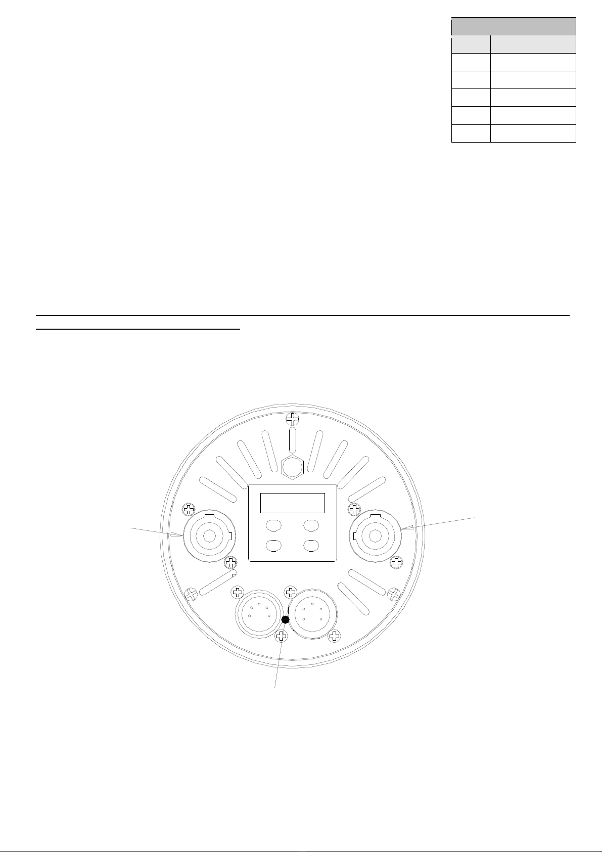
HPLED II 6 Module
Rear metal cover with input connections
Blue Neutrik Power on connector
This owner's manual
Safet information for the use of the HPLED and periodical maintenance of unit.
Users must scrupulously comply with information/indications that follows
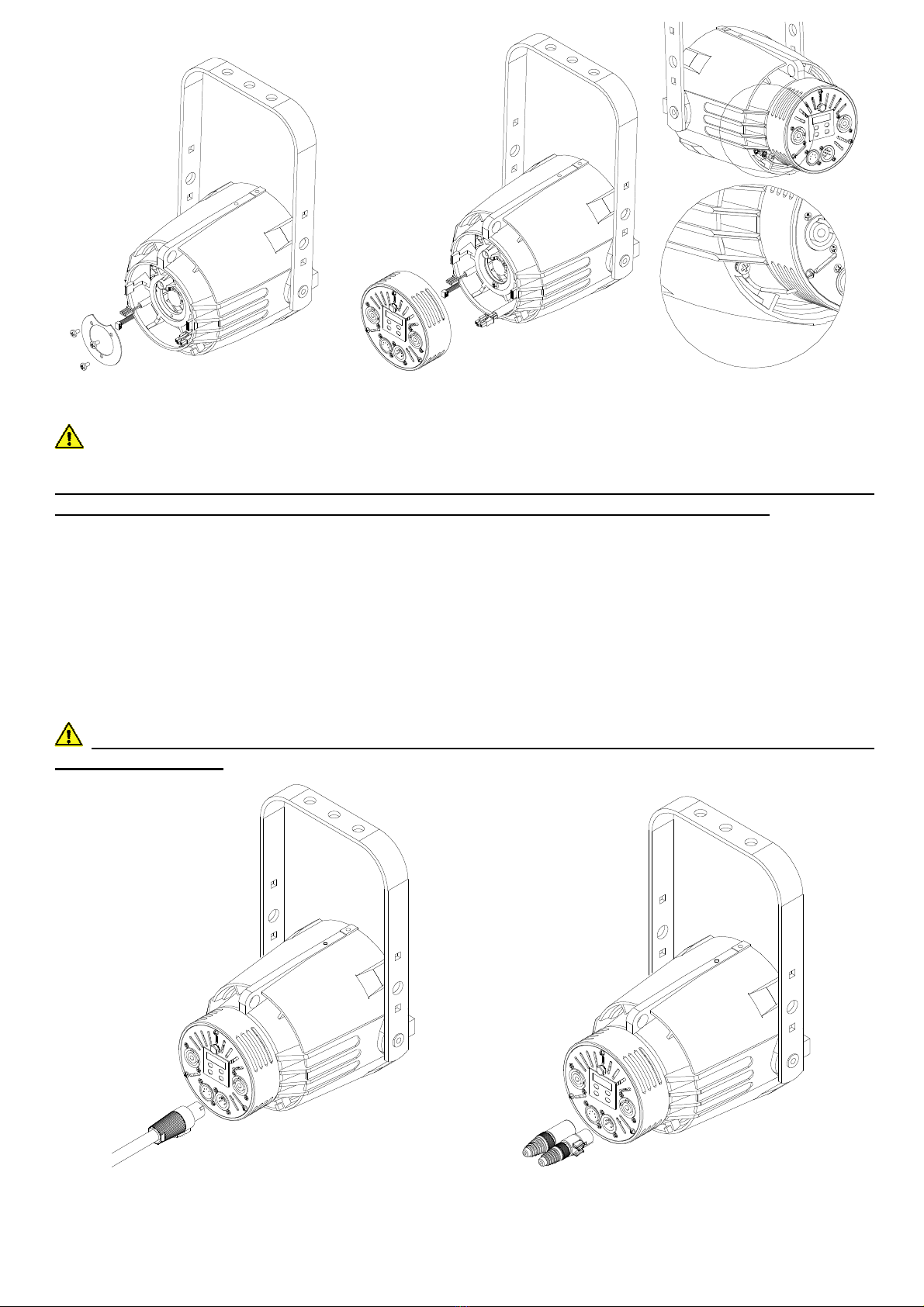
HPLED II 6 must be installed on original “ ETC source 4” fixture only. Any other use will void warranty and
will free the manufacturer of any sort of responsibility and liability.
Never utilise HPLED II 6 assembly alone as it must always be housed in original ET Source 4 barrel.
Minimum distance from any flammable source is of 0.25m.
Minimum throw distance from illuminated surface: 0.5m.
Installation of the unit(s), including external source4 body, must be secured with adequate clamps, safety
cords, nuts and bolts to bear at least 4 times the weight of the whole unit(s)
Always Power HPLED II 6 to safety circuit breakers
Install HPLED II 6 in ventilated ambient which temperature must not exceed 35°
HPLED II 6 is NOT for domestic use. HPLED II 6 can only be used for professional applications
Some outer parts of the ET Source4 can reach temperatures of up to 60 ° when HPLED is operated
HPLED II 6 must be fitted with protection shields (Lenses)
On no account, directly or indirectly, LED must be touched as it may impair its use.
An Essential and Periodically throughout cleaning of the HPLED is recommended. This practice avoids that
layers of dust and other impurity jeopardise and reduce the correct operation of the unit. Lenses must be
cleaned to remove layers of dust that may impede and or reduce the passage of the light through the lenses.
The correct and periodically maintenance keeps also fans and vents clean thus keeping the HPLED II 6 in
its best performance conditions. Never touch, directly or indirectly, the Yellow core of the LED nor use
solvents that can damage the LED irremediably. Protection shields if battered/worn, must be replaced with
new ones (Lenses)
Warning from electric shocks
All operations must be accomplished, handled and carried out by qualified personnel only
Warning High voltage hazard, always disconnect Power before any handling and any servicing of
HPLED II 6
Do not and never handle HPLED II 6 with humid/wet hands or near to any water or any kind of moisture
sources
Always connect HPLED to mains fitted with safety device switch that cuts power off in case of danger
The HPLED does NOT and CAN NOT be operated via Phase control dimmer nor
connected/operated in NON-DiM mode
HPLED II 6 is rated lass I
Earth connection is mandator !
CE Approvals
The HPLED II 6 products to which this manual refers to, complies with European directive pursuant to:
2014/35/EU safety of electrical equipment supplied at low voltage (LVD)
2014/30/EU Electromagnetic compatibility (EM )
2011/65/EU Restriction of the use of certain hazardous substances (RoHS)
WARRANTY!
A 24-month warranty is granted on the HPLED II 6 from purchase’s date. Warranty covers fabrication
defects only. Warranty is immediately voided if the HPLED II 6 has been handled by unqualified personnel.
Any improper and unauthorised use, such modification(s) or misapplication of the HPLED II 6 will also void
the warranty of the product(s). Silver colour label showing technical data and serial number, if removed or if
data are impaired to render details illegible, it will immediately void the warranty

Page 3 / 12
Technical specifications
Power Supply 100-240 V~ 50/60Hz
Maximum power consumption 175W
Stand-by power consumption 3W
Minimum ambient temperature -10°
Maximum ambient temperature 35°
LED olour RGBA L: Red; green; blue; amber; cyan; lime
30 colored presets
10 Preset bianchi da 2.300°K a 10.000°k
LED RI:
Minimun RI
: 93> and 98
>
(depending on the selected white)
10 white presets from 2,300 ° K to 10,000 ° k
LED Life (see Manufacturers ’ specifications)
Weight: 2,49 Kg
IP Rating:
To be housed into original ET Source four fixture only
Working position: Any
Power connectors: IN & OUT Neutrik Power on
Data connectors: IN & OUT XRL5
Data protocols: DMX 512; RDM ready
User interface: 4-digit display and 4 buttons
Manual operation:
Users must operate via buttons provided on the display
Fan control: Fan speed adjustment
ontrol of LED frequency: Selection of LED frequency refresh
4 Dimming curves control: Selection of four dimming curves control
ompliant:
Dimensions (see picture):

Page 4 / 12
HPLED C 5 installation
HPLED II 6 has been designed to be installed in any original “ET source 4” fixtures. Some parts of the
existing “ET Source 4” fixture must be removed to lodge the module in
ourse of actions:
1.
Disconnect an kind of power/source from an item being handled, that could cause electric
shock
2.
Loosen knobs that hold front lens assembly, remove it and place it aside in a safe place
3.
Locate rear section of the Source 4 fixture, then start loosening knob that holds the round plate in place
until it is totally separated from the main body. You may either store or scrap this part. HOWEVER
LOCK-WASHER AND THE M4 SCREW USED TO HOLD THE GROUND CORD ON THE ETC
SOURCE4 BODY MUST BE SECURED ASIDE AS THEY WILL BE USED FOR THE NEW GROUND
CORD PROVIDED WITH THE HPLED II C6 FIXTURE.
4.
As of now onwards for our own safet we recommend ou to wear protection gloves and
safet transparent e e protection goggles.
We advise ou to watch the video at this link
https://www. outube.com/watch?v=x489dXR8bu0&t=31s (in the YOUTUBE search box,
t pe: “Ellisoidal glass reflector removal from Source”). This will help ou to disassemble the
glass reflector.
5.
Place HPLED II 6 on working bench and start loosening the 3 M4 screws that hold the metal ring
(marked by red arrow in figure 2).
6.
Accommodate the HPLED II 6 in the Source4 body. Ensure the correct inward direction is followed as
remarked by the 2-red-round ring references. Make also sure to follow the red arrow direction as shown
in figure 3. During such operation make sure that the 3 connecting cables (i.e. power cable, DMX cable
and display cable) are not squeezed, while being lead through loop-holes during reassembling of the unit.
7.
Remount the metal ring to its former position; tighten now the 3 provided M4x6 screws to their full
extent. Do not exceed nor force tightening.
8.
onnect the 3 lead-cables to the rear metal cover provided, ensure that connectors are inserted in the
correct side. Special attention must be paid to the flat cable as it must be handled with extreme care
while connecting its ends. (if flat cable is squeezed or impaired it can cause malfunctionings to the
product)
9.
Ensure that all cable connections are neatly and clearly set to their positions avoiding any contact,
interference, interconnections, interpositions with fans and other interfering components that might
collide, squeeze hamper the correct operations and eventually damage the product.
10.
Remount the rear metal cover to the Source 4 body using any 11mm spanner; tighten the screw to its
full extent. Do not exceed nor force tightening.
11.
The lock washer and the M4 screw used for holding the eyelet-cord to ground the fixture as expressed in
point 3, must be now used to secure the new provided eyelet-cord to ground/earth the fixture as shown
in fig.6
Fig.1 Fig.2 Fig.3

Page 5 / 12
B
Fig.4 Fig.5 Fig.6
Connection to mains
WARNING ! Installation(s) must be accomplished, handled and carried out b qualified
personnel onl and must compl with all norms in force in the installation's countr
HPLED II 6 is supplied with a free-Blue Neutrik Power on plug that must be wired using a 3x1.5mm² lead
which additional specifications include:
Operating Voltage: 300/500V
Test Voltage: 2KV
Operating Temperature: -10° / +35°
onnect blue wire to N terminal, brown wire to L terminal and Yellow/Green wire to earth terminal. Ensure
the use of safety circuit breaker at all times. Daisy chain of up to 10 units is permitted when connected to
230VA . Daisy chain of up to 5 units is permitted when connected to 110VA . Maximum daisy chain length:
20m.
WARNING:NEVER CONNECT HPLED II C6 ENGINE TO ANGLE PHASE DIMMER PACK NOR
TO NON-DIM MODE
Fig.7 Fig.8

Page 6 / 12
Signal control connection
HPLED II 6 can be operated via either DMX512A and or RDM ready Protocols. For
Daisy chain DMX line use a-2 lead wire plus shield.
Red led blinks when DMX Input is available. DMX off line when led is off
RDM – Remote Device Management
RDM ontroller allows for remote standard operations
RDM default options include:
Discovery mode: RDM is engaged when controller incepts this mode, the device reports itself by giving a
flash of light ( ontroller sets the device in a listing to read: settings, DMX address, personality settings,
(Read all DMX mode including all DMX channels above)
ON/OFF ”Identify”: This mode is used to identify the manufacturer’s device (Lites srl). It gives a flash of
light from the LED
Model information (HPLED II- 6)
Software version information (HPLEDII – 6 v.x.xx)
Mode to reveal temperatures of the LED and of the driver
Mode to reveal hour-meters of the LED and of the device
Power HPLED II C6 ON
WARNING ! Before powering HPLED II C6 ensure that all installation(s) procedure(s) have(s)
been properl set and accomplished.
When HPLED II 6 is powered the setup display will show the software release version. The UP, DOWN,
ENTER and ES buttons will allow for the operations of HPLED II 6 menu. UP and DOWN buttons allow to
browse through menu options, the ENTER button is to confirm selection. The ES button is to return to the
previous menu or to quit previous setting(s).
UP
DOWN
ENTER
ESC
POWER OUT
WHITE POWER IN
BLU
XRL 5 DMX IN-OUT
DMX XLR 5 Pin As sigment
pin
Description
1
GND
2
DMX-
3
DMX+
4
Not connected
5
Not connected

Page 7 / 12
Menu items
Displa ed
Message
Allowed or
displa ed
values
Function
Addr
001..5
12
Set Up DMX Address
Auto
(Automatic mode)
co01
co02
co03
co04
co05
co06
co07
co08
co09
co10
co11
co12
co13
co14
co15
co16
co17
co18
co19
co20
co21
co22
co23
co24
co25
co26
co27
co28
co29
co30
co31
co32
co33
co34
co35
co36
co37
co38
co39
co40
Preset 1 red
Preset 2 light red
Preset 3 orange
Preset 4 medium amber
Preset 5 amber
Preset 6 straw tint
Preset 7 pale yellow
Preset 8 spring yellow
Preset 9 yellow
Preset 10 lemon yellow
Preset 11 lime
Preset 12 lime green
Preset 13 green
Preset 14 moss green
Preset 15 light cyan
Preset 16 cyan
Preset 17 peacock blue
Preset 18 summer blue
Preset 19 bright blue
Preset 20 light steel blue
Preset 21 light blue
Preset 22 slate blue
Preset 23 blue
Preset 24 deep lavender
Preset 25 lavender
Preset 26 magenta
Preset 27 rose pink
Preset 28 dark pink
Preset 29 bright pink
Preset 30 Rainbow
Preset 31 white 2300°k
Preset 32 white 2700°k
Preset 33 white 3200°k
Preset 34 white 4000°k
Preset 35 white 5600°k
Preset 36 white 6500°k
Preset 37 white 7000°k
Preset 38 white 8000°k
Preset 39 white 9000°k
Preset 40 white 10000°k
It’s possible to select 30 colored
presets and 10 fixed white presets,
without the aid of the DMX 512
signal. By selecting the value
indicated from co01 to …… co40 you
choose the combined color. When
you turn off the projector the
selected preset will be saved. In each
preset
you can change the output
color level.
Select the preset that needs to be to
be changed. If you press once the
Enter button, the display will show r
(red) with the set value, then if you
keep pressing Enter, G (green), b
(blue), A (amber), c (cyan), L (lime),
S (strobe), n (Rainbow), d (dimmer)
will be displayed one by one.
Use the Up and Down button to
adjust the level of the 6 colors + the
3 functions n (raiwbow), S (strobe), d
(dimmer), pressing them one by one
from 0 to 255, to determine the
output color.
Always confirm with Enter to save the
settings.
Pr01
Pr02
Pr03
Pr04
Program 1: auto
Program 2: auto
Program 3: auto
Program 4: auto
Automatic mode without DMX 512 Protocol
signal.Program selections run between Pr01
through Pr 04. Both programs can be
modified. To change program select Enter
then view (Scn0…Scn6; max scenes of each
program). licking on enter once more it
shows P.00.0 (time) followed by F.00.0
(speed) and ultimately the last view shows
1c.01… though c40 (colour to be assigned to
each scene) The use of UP/Down keys allow
for setting values. When selections are
completed press enter to confirm.

Page 8 / 12
MASL
Master Mode
The Master Mode uses the same settings as the Auto Menu. The only
exception is that when all fixtures are connected to DMX 001 in daisy-
chain, they perform the same presets and or the same presets selected
on the Master fixture. The slave projectors must be set in 9ch mode.
ModE
12
ch (D)
RGBA
L
12
ch
(default)
Dmx mode (view next page)
2
ch
2 ch
16 ch
RGBA L 16 ch (16 bit)
6 ch
RGBA L 6 ch
RGB
RGB 6 ch
HSI
Stubio HSI
6 ch
9
ch
9 ch
drUt
..°
Shows driver operating temperature
LEdt
..°
Shows leds operating temperature
PUM
0..100%
Shows current led power (0
-
100%)
SMoo
FAST
MED
SLOW
DMX data Speed adjustment
GAMM
qUAd
S Ur
qUAd2
LInE
Dimming curves available
FrEq
1K
2K
3K
4K
5K
6K
7K
8K
9K
10K
LED operation frequence
booS
Off
on
When OFF,
LED max flux :
9
0%
When ON, LED max flux : 100%
FAn
Aut
MEDH
MEDL
LOW
4 fan operating modes i.e atuomatic, medium fast, medium slow, slow
speed.
Fan speed adjujstments (fan-sound) reflect on self-correct output LED
brightness and other factors as room-temperature, number of engaged
channels
PoS AA
VV
Dis
play orientation selection:
AA = normal
VV = inverted
StbY Off
on
Standby display activity:
off = display always switched on = display switched off after few
seconds of buttons inactivity (only the right side dot will be lighted to
indicate DMX availability)
dEF
SUrE
ON Will restore the default factory values
SoFt
Shows Software version
DMX Operating Modes (Mode)
Selecting 1 of the 7 available modes it enables the number of channels required, and its relevant modes,
needed to operate HPLED II 6

Page 9 / 12
mode 12 ch RGBACL (default)
Ch Function
Dmx levels
1
red
0..255 From 0 to max 255
2
green
0..255 From 0 to max 255
3
blue
0..255 From 0 to max 255
4
amber
0..255 From 0 to max 255
5
c an
0..255 From 0 to max 255
6
lime
0..255 From 0 to max 255
7
strobe
0…15 Strobo disingaged
16…255 Strobo from slow (16) to fast (255)
8
Rainbow
0..15 Rainbow disingaged
16..255 Rainbow from slow (16) to fast (255)
9
dimmer
0..255 From 0 to max 255
10
(priorit on
channel 11)
White selection
0…15
Deserted whites
16…17 2300°k cri 93
18…38 from 2300°k to 2700°k
39…40 2700°k cri 97
41…61 from 2700°k to 3200°k
62…63 3200°k cri 98
64…84 from 3200°k to 4000°k
85…86 4000°k cri 95
87…107 from 4000°k to 5600°k
108…109 5600°k cri 98
110…130 from 5600°k to 6500°k
131…132 6500°k cri 95
133…153 from 6500°k to 7000°k
154…155 7000°k cri 93
156…176 from 7000°k to 8000°k
177…178 8000°k cri 96
179…199 from 8000°k to 9000°k
200…201 9000°k cri 93
202…222 from 9000°k to 10000°k
223…225 10000°k cri 95
3200 ° k halogen lamp
operation
226…255
halogen lamp dimming simulation
11
Color selection
0…15 No color
16..23 red
24…31 light red
32…39 orange
40…47 medium amber
48…55 amber
56…63 straw tint
64…71 pale ellow
72…79 spring ellow
80…87 ellow
88…95 lemon ellow
96…103 lime
104…111 lime green
112…119 green
120…127 moss green
128…135 light c an
136…143 c an
144…152 peacock blue
153…159 summer blue
160…167 bright blue
168…175 light steel blue
176…183 light blue
184…191 slate blue
192…199 blue
200…207 deep lavender
208…215 lavender
216…223 magenta
224…231 rose pink
232…239 dark pink
240…247 bright pink
248…255
FULL RGBACL
12
Fan speed
0..25 Auto speed or set from menu
26..255 Fan speed from slow to fast

Page 10 / 12
mode 2 ch
1
olor selection
0…
15
No color
16
…
20
red
21
…
25
light red
26
…
30
orange
31
…
35
medium amber
36
…
40
amber
41
…
4
5
straw tint
46
…5
0
pale yellow
51
…
55
spring yellow
56
…
60
yellow
61
…
65
lemon yellow
66
…
70
lime
71
…
75
lime green
76
…
80
green
81
…
85
moss green
86
…
90
light cyan
91
…
95
cyan
96
…
100
peacock blue
101
…
105
summer blue
106
…
110
bright blue
111
…
115
light steel blue
116
…
120
light blue
121
…
125
slate blue
126
…
130
blue
131
…
135
deep lavender
136
…
140
lavender
14
1
…
145
magenta
146
…
150
rose pink
151
…
155
dark pink
156
…
160
bright pink
161…165
Full RGBA L
White selection
166
…1
70
white 2300°k
17
1…1
7
5
white 27
00°k
176
…1
80
white 32
00°k
18
1…1
8
5
white 4
000°k
1
8
6…1
90
white 56
00°k
19
1…1
9
5
w
hite 65
00°k
1
9
6
…200
white 7
000°k
201…20
5
white 8
000°k
206
…
210
white 9
000°k
211
…
215
white 10
000°k
Rainbow
216…225
Rainbow
from slow
(191)
to fast
(229)
Sequence rainbow R-G-B-A- -L
3200 ° k halogen lamp
operation
226…255
halogen lamp dimming simulation
2
dimmer
0..255
From 0 to max 255

Page 11 / 12
mode 16 ch RGBACL 16 bit
h
Function
dmx levels
1
red
0..255
From 0 to max 255
2
Red fine
0..255
Red fine tune adjustment
3
green
0..255
From 0 to max 255
4
Green fine
0..255
Green
fine tune adjustment
5
blue
0..255
From 0 to max 255
6
Blue fine
0..255
Blue fine tune adjustment
7
amber
0..255
From 0 to max 255
8
amber fine
0..255
amber fine tune adjustment
9
cyan
0..255
From 0 to max 255
10
cyan fine
0..255
cyan
fine tune adjustment
11
lime
0..255
From 0 to max 255
12
lime fine
0..255
lime fine tune adjustment
13
strobe
0…15
Strobe disingaged
16…255
Strobo from slow (16) to fast (255)
14
dimmer
0..255
From 0 to max 255
15
Dimmer fine
0..255
Adjustment of global fine light intensity
16
Fan speed
0..25
Auto speed or set from menu
26..255
Fan speed from slow to fast
mode 6. ch RGBACL
h
Function
dmx levels
1
red
0..255
From 0 to max 255
2
green
0..255
From 0 to max 255
3
blue
0..255
From 0 to max 255
4
amber
0..255
From 0 to max 255
5
cyan
0..255
From 0 to max 255
6
lime
0..255
From 0 to max 255
mode 6.RGB 6 ch
mode 9 ch
h
Function
dmx levels
1
red
0
…
255
Fr
om 0 to max 255
2
green
0
…
255
From 0 to max 255
3
blue
0
…
255
From 0 to max 255
4
amber
0
…
255
From 0 to max 255
5
cyan
0
…
255
From 0 to max 255
6
lime
0
…
255
From 0 to max 255
7
strobe
0
…15
Strobo disingaged
16…255
Strobo from slow (16) to
fast (255)
8
Rainbow
0…15
Rainbow disingaged
16...255
Rainbow from slow (16) to fast (255)
9
dimmer
0
…
255
From 0 to max 255
1
Red
0..255
From 0 to max 255
2
Green
0..255
From 0 to max 255
3
Blue
0..255
From 0 to max 255
4
Dim
mer
0..255
From 0 to max 255
5
strobe
0…15
Strobe disingaged
16…255
Strobo from slow (16) to fast (255)
6
Fan speed
0..24
Auto speed or set from menu
2
5
..255
Fan speed from slow to fast

Page 12 / 12
mode 6.HSI STUDIO 6 ch
1
Hue
0..255
Hue selection, following levels
R, R+L, R+G+L, G+L,G, G+ ,G+B+ , B+ , B B+A, R+B+A, R+A, R
2 Saturation 0..255
olor saturation with set color in the Hue channel
3 Dimmer 0..255
From 0 to max 255
4
strobo 0…15
Strobe disingaged
16…255
Strobo from slow (16) to fast (255)
5
(priorit on
channel 1)
Selection
whites
0…15
Whites off
16…18
2300°k cri 93
19…41
from 2300°k to 2700°k
42…44
2700°k cri 97
45…67
from 2700°k to 3200°k
68…70
3200°k cri 98
71…93
from 3200°k to 4000°k
94…96
4000°k cri 95
97…119
from 4000°k to 5600°k
120…122
5600°k cri 98
123…145
from 5600°k to 6500°k
146…148
6500°k cri 95
149…171
from 6500°k to 7000°k
172…174
7000°k cri 93
175…197
from 7000°k to 8000°k
198…200
8000°k cri 96
201…223
from 8000°k to 9000°k
224…226
9000°k cri 93
227…249
from 9000°k to 10000°k
250…255
10000°k cri 95
6
Fan speed
0..24 Auto speed or set from menu
25..255 Fan speed from slow to fast
Error messages
In case of malfunction, the following messages can be shown:
Led sensor error: the sensor on the led is faulty.
Overtemperature LED: the temperature on the LED exceeds the allowed limit, check if the fan is working.
Micro overtemperature: the temperature on the driver board exceeds the allowed limits, check if the fan is working.
Micro sensor error: the sensor on the driver board is faulty.
If these malfunctions occur, the LED turns off.
Avoid using the HPLED II 6 and promptly contact any authorized service centre.
Periodical maintenance
To ensure the correct HPLED II 6 operation, we suggest the following periodical maintenance operations:
Remove dust or any kind of other dirt from the fans and loop-holes, this operation ensures the correct air flow
Remove dust from lenses using a clean cloth. This will ensure the maximum light efficiency
Replace damaged protection screen and lenses when necessary.
Do not touch nor clean the LEDs nor the sourranded area with solvent
Device disposal information
At the end of its life, HPLED II 6 must be disposed to an appropriate electrical and electronic equipment
waste collection centre. Eco-friendly disposal, helps to avoid possible negative impact on the environment
and human health and promotes the reuse and/or recycling of the materials making up the product. Illegal
disposal involves administrative sanctions provided by laws enacted.
Note
Manufacture declines any sort of personal/corporate responsibility/liability for damages caused by people that are not
scrupulously following indications given in this manual as for the inadequacy or for misuse of the product they do, as
well as if the product has been handled by unqualified personnel. Not complying with security norms/periodical
maintenance and all information contained and as expressed in the owner's/service manual will also totally free
personal/corporate responsibility/liability.
Text, wordings, drawings, specifications, modifications and other
changes of this manual may apply anytime without notice. The specifications are not binding.
HPLED II 6 color 22/03/2020 rev.00
Table of contents
Other Lites Dj Equipment manuals