- 10 - - 11 -
4. Assembly
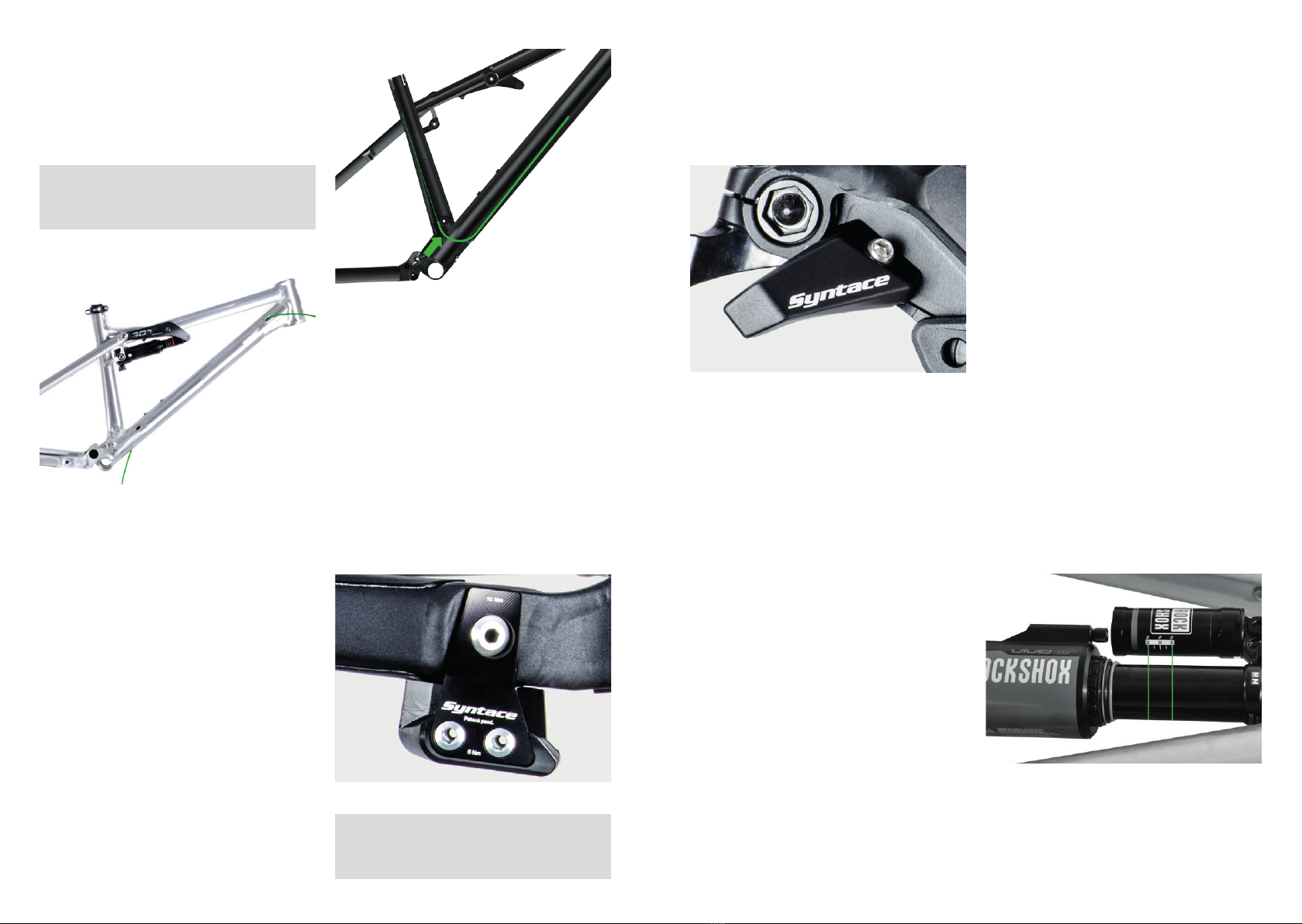
Frame preparation
The contact surfaces (bottom bracket, disk
brake socket, seat tube) are fully prepared
for the assembly� In case you face problems
during the assembly, please directly contact
Syntace�
Note: The seat tube is manufactured
particularly accurately for the Eight-
pins variable seatpost with very small
tolerances only� This is why it must not
be changed in any way�
Note: In case the frame is painted or
anodized after the purchase, make sure
that the inner diameter of the seat tube
remains the same for the entire 140 mm
insert length�
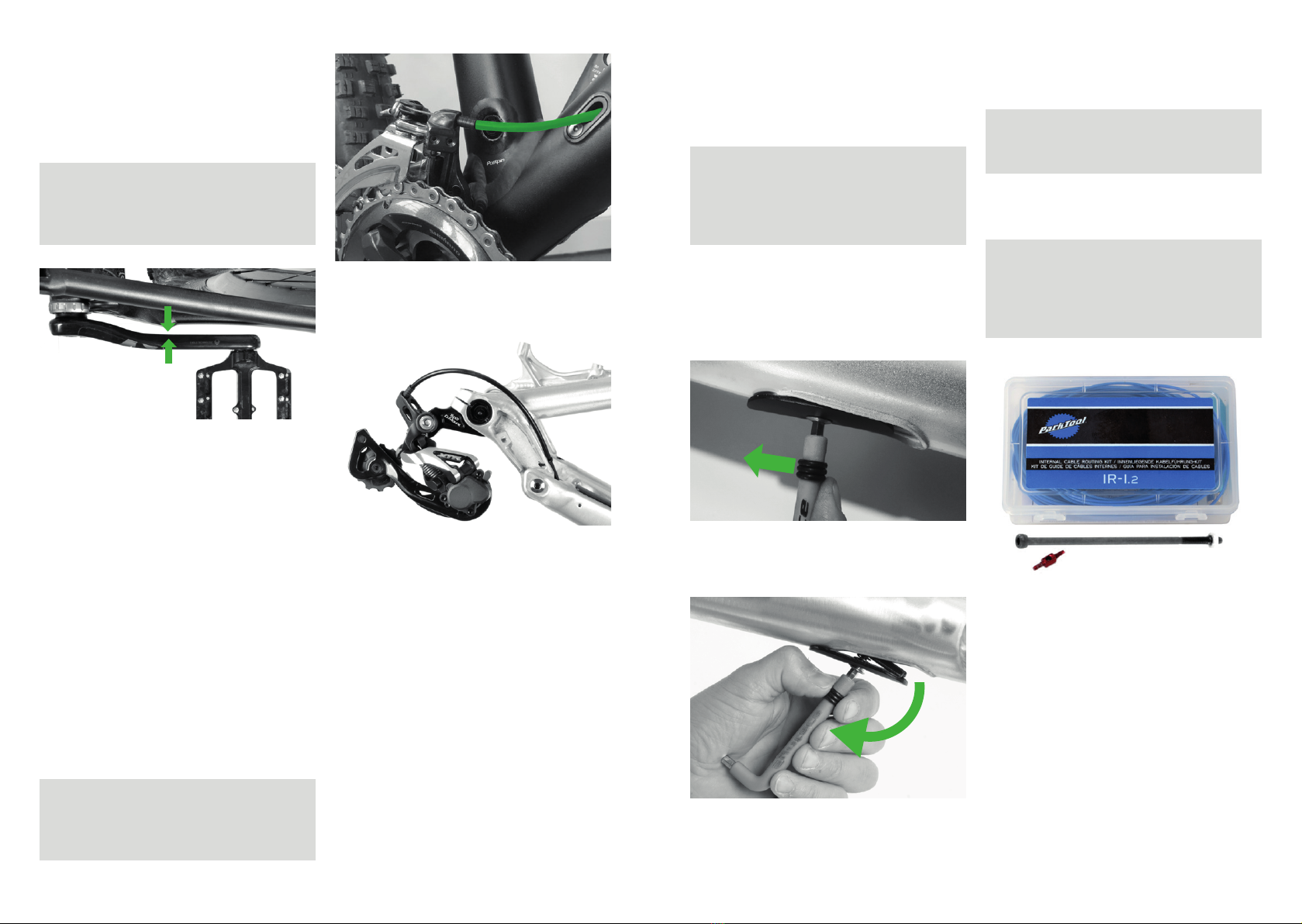
Seatpost / seat
The 601 Mk4 is designed for variable
seatposts with internal cable routing�
The assembly is simplified thanks to the
ServicePort at the lower end of the down
tube close to the bottom bracket�
VPlease refer to the extra manual of
Eightpins that exemplifies the assembly
process with a Liteville 601 Mk4�
Note: the standard Eightpins variable
seatpost interface at the seat tube is
adapted already and does not need to be
changed�
Using a common seatpost, the frequent
changing of the seat height leads to a
certain wear of the seatpost and the seat
tube� For carbon fiber seatposts, this wear
is considerably higher than for Aluminum
seatposts� In order to minimize the wear,
please clean the seatpost and seat clamp
after every ride in the rain� The diameter of
the seatpost must never become less than
34�7 mm at any point� If this is the case,
please exchange the seatpost as it might
result in damages of the frame�
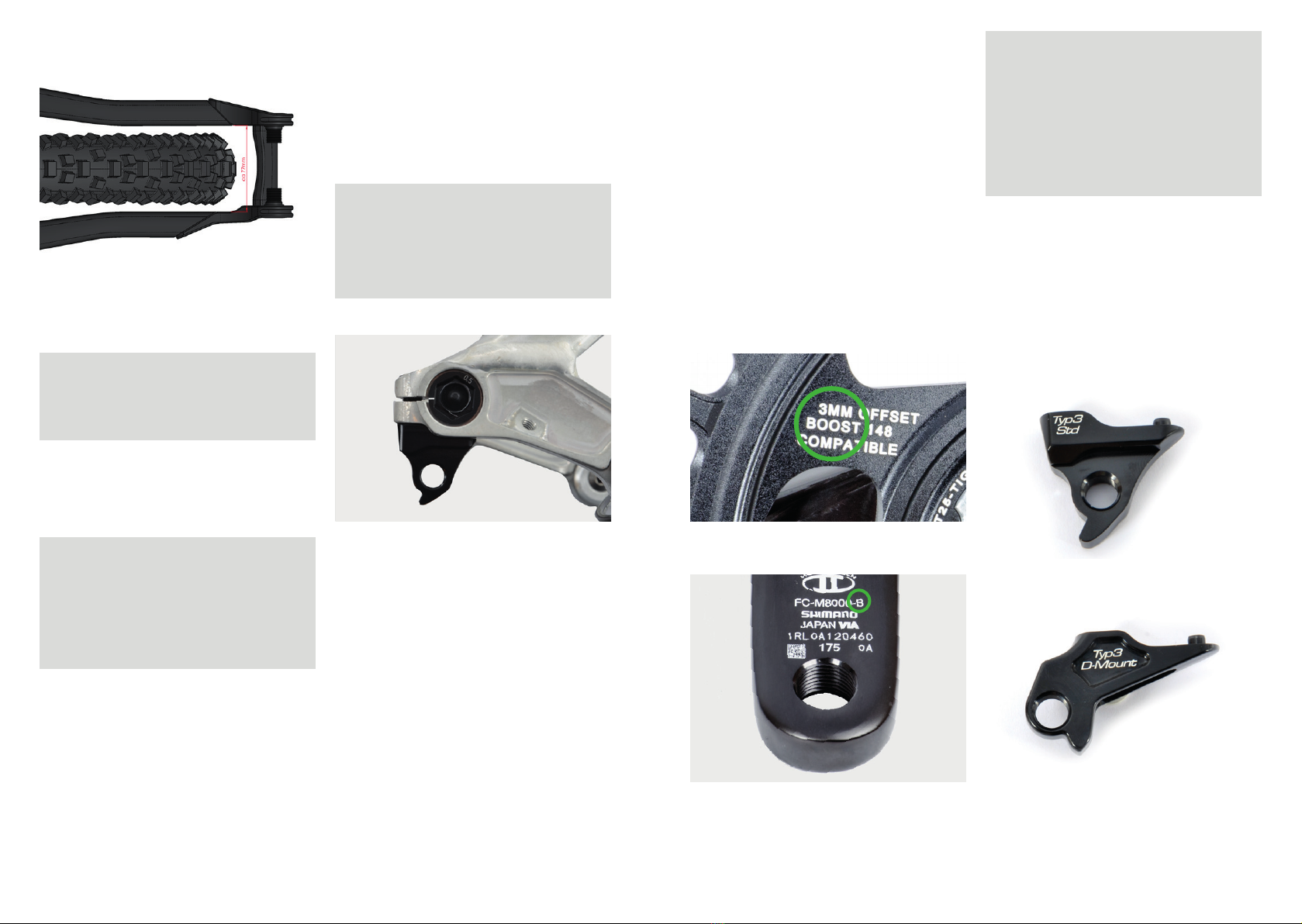
Headset / fork
The frame comes with nothing but the cone
and the cover cap for tapered fork steer
tubes (see picture)�
Advice: Reduction kit for 1 1/8“-fork
steer tube: Syntace Art�# 14593
Make sure all parts of the headset including
the bearings are greased before the
assembly� Put the bigger (1,5”) cone on the
fork, which is to lay evenly on the fork crown�
The fork can now be inserted into the frame
before the smaller (1 1/8”) cone is put on the
fork steer tube� Installing the cover cap is
the last step of the headset assembly�
Advice: Using a Syntace MegaSpacer, a
silver 0�6 mm washer needs to be added
between the SuperSpin cover cap and
the MegaSpacer� The washer is included
in the MegaSpacer package or can be
ordered separately as a spare part at
Syntace�
Advice: Tighten the adjustment screw of
the Ahead star nut hand-tight� Loosen it
again thereafter with about ¾ revo-
lutions and only in the next, last step
adjust the bearing play of the headset
bearing� Following this procedure, you
make sure that the bearings sit evenly
in the bearing shells� The result should
be that the fork can be turned easily
without any bearing play� It may be
necessary to repeat the process after
the first ride�
Handlebar / stem
Mount and adjust the handlebar and stem
according to the Syntace manual�
Shift and brake levers
Mount and adjust the shift and brake levers
according to the manufacturers’ manuals�
Advice: Tighten the screws of the brake
and shift levers only so much that they
can still turn in case of a crash� This
might avoid a lever to brake apart and
additionally protects the thin walls of
your handlebar�