Cervélo R5 Disc User manual

R5 RETAILER ASSEMBLY MANUAL

1 2
TABLE OF CONTENTS
This manual is intended to guide ocial Cervélo retailers through the assembly and adjustment
of the Cervélo R5. This manual outlines the process and procedure associated with the
installation of Cervélo components, as well as the routing of shifting and braking control lines
only. Proprietary parts referenced in this manual are available only through Cervélo Cycles Inc.
Failure to use the specied parts and follow these assembly instructions, may result in loss
of control while riding; and lead to serious injury. This manual is not intended to replace the
assembly and service instruction provided by third-party component manufactures, and assumes
that the assembler is a trained, professional bicycle mechanic. See https://www.probma.org/
CER-R5-V2 2022-07-29
IMPORTANT INFORMATION
NOTE: Cervélo strongly recommends that
all assembly and adjustment procedures be
performed by an authorized Cervélo retailer.
If you are a Cervélo R5 consumer/purchaser
reading this manual we suggest that
before attempting to undertake any of the
procedures in this manual that you consult
your authorized Cervélo retailer, or visit
us at www.cervelo.com/support
NOTE: This manual was developed
to compliment the Cervélo General
User Manual, and is intended as
a supplement to the assembly and
installation instructions supplied by
the component manufacturers (provided
with this bicycle).
NOTE: All non-proprietary components
such as those from Shimano or SRAM are
available from your local distributor.
LIST OF TOOLS & SUPPLIES
This manual outlines a number of procedures
for making adjustments to the R5 bicycle. The
following tools and parts listed are required for
these adjustments. Cervélo strongly recommends
that all assembly and adjustment procedures be
performed by an authorized Cervélo retailer.
Important Information .................. 1
List of Tools & Supplies. . . . . . . . . . . . . . . . . 2
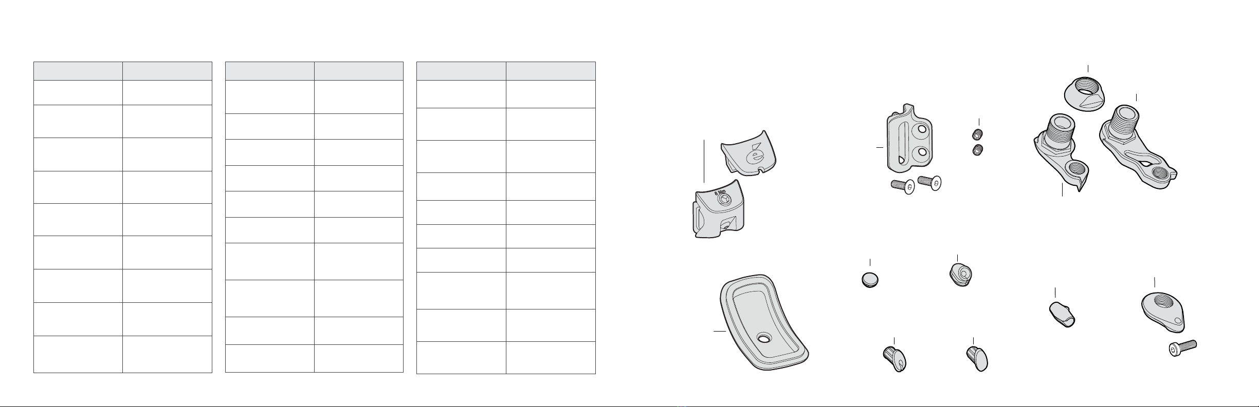
R5 Parts List ...................... 3
Small Parts ....................... 4
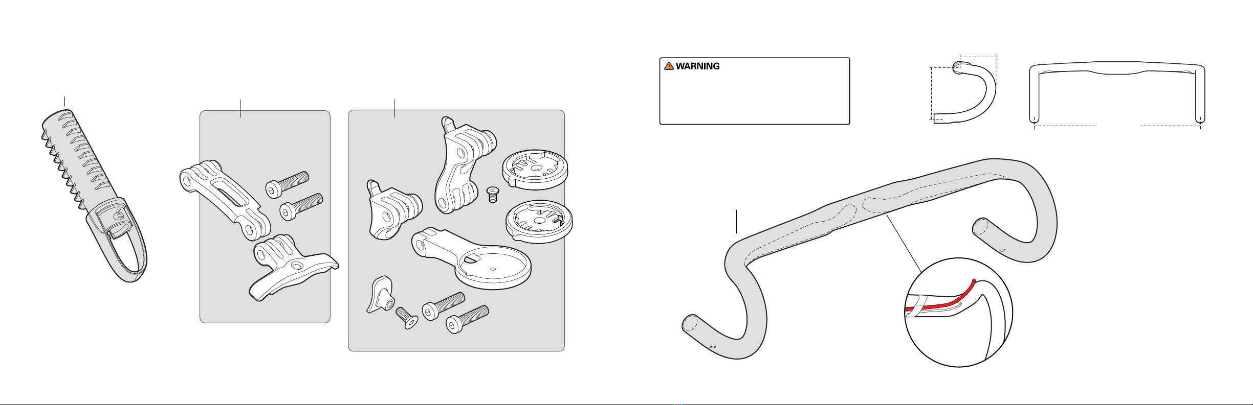
HB13 Handlebar ..................... 6
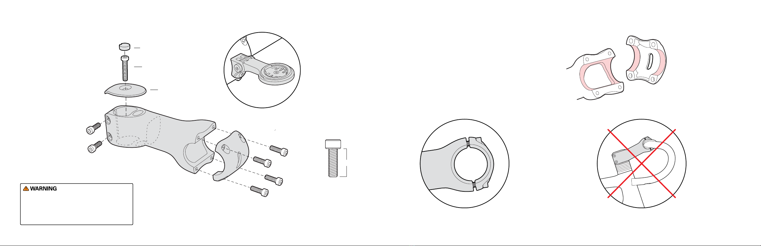
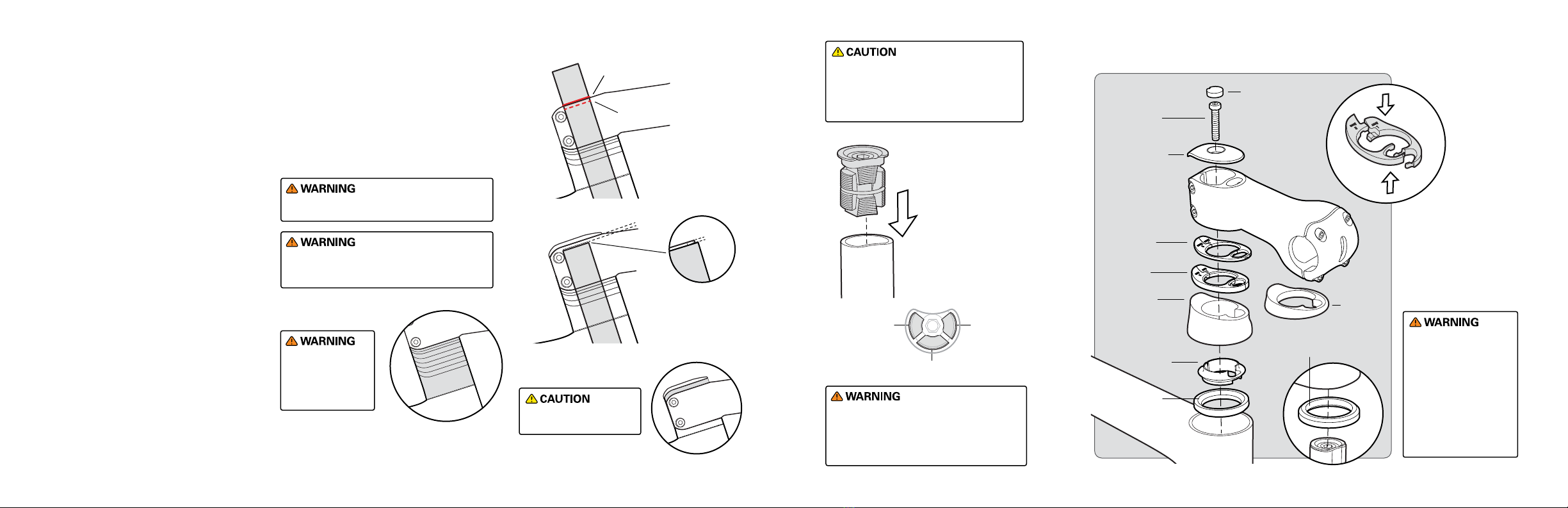
ST31 Stem ........................ 7
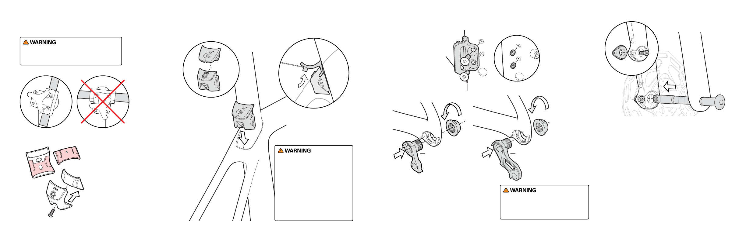
Frame & Component Preparation .............. 9
Seatpost Assembly & Installation.............12
Fork Preparation & Installation .............13
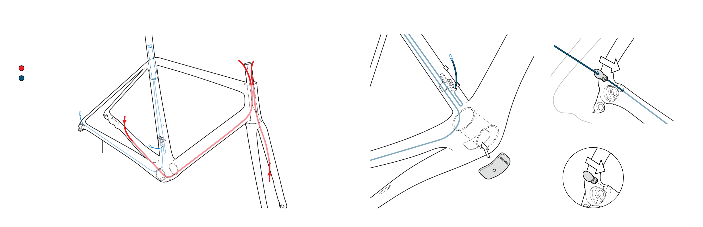
Brake Hose Routing. . . . . . . . . . . . . . . . . . . . 15
Electric Wire Routing & Installation. . . . . . . . . . . 17
Di2 Battery Installation. . . . . . . . . . . . . . . . . 19
Tire/Rim Clearance. . . . . . . . . . . . . . . . . . . . 20
Aero Thru-Axle Installation ...............21
R5 Frame Details.....................23
R5 Frame Geometry ....................24
Cervélo Customer Support. . . . . . . . . . . . . . . . . 25
Tools
Bicycle workstand (types which
secure bike by the seatpost, or
pro-type stand with fork mount)
Torque wrench(es) with 2.5Nm to
15Nm range and adaptors:
Allen (Hex) head inserts:
2mm, 2.5mm, 3mm, 4mm, 5mm,
6mm, 8mm, 10mm
Open ended wrenches:
7mm, 8mm, 10mm, 17mm
Cable cutters
Pliers
Phillips-head screwdriver
Slot-head screwdriver
Tools
Pedal wrench
Brake rotor lockring tools
Hydraulic bleed kit
Isopropyl alcohol
Di2 wire tool – Shimano
Good quality bicycle grease &
carbon assembly compound
Saw cutting guide (Park Tool SG-7.2
or equivalent)
Hacksaw (with carbon and
aluminum specic blades)

3 4
R5 PARTS LIST
Item Description Cervélo Part No.
BB Blanking Plug GR-BB-140
Rear Derailleur
Hanger w/Fixing Nut DRH-WMN112
Shimano Direct Mount
RDH w/ Mounting Nut DRH-SDM
Threaded Fork Insert
w/Fixing Screw QRI-THD
Seat Tube Blanking
Plug(1x & Wireless) GR-ST-CLOSED
8mm Seat Tube Di2
Wire Grommet GR-ST-JGW
Brake Hose Guide CBG-DBH
FDM Blanking Screws
(1x) SS-FDM-192
Front Derailleur
Mount w/ Fixing
Screws
FDM-2017
Item Description Cervélo Part No.
Dropout Blanking Plug
Wireless GR-DRPOUT-CLOSED
Dropout Electric Wire
Guide GR-DROPOUT-GUIDE
SP24 Seatpost w/
Head 0mm SP-SP24-ZERO
SP24 Seatpost w/
Head 15mm SP-SP24-15MM
Seatpost Battery
Mount MT-BINT-SP2
Seatpost Clamp w/
Cover SPC-0H0R5
Cervélo Front Aero
Thru Axle - Removable
Handle
QRA-AERO2-F
Cervélo Rear Aero
Thru Axle - Removable
Handle
QRA-AERO2-R
Cervélo Front Aero
Thru-Axle QRA-AERO-F
Cervélo Rear Aero
Thru-Axle QRA-AERO-R
Item Description Cervélo Part No.
Rubber Plug for ST32
Top Cap PL -338
D-Shaped
Compression Plug FKI-CL005-517A
Accessory Mount Kit
(Front) MT-LM-F-004
Accessory Mount Kit
(Rear) MT-LM-R-003
Chainstay Protector PRO-CS-508
Split Ring 312 SR-312
ST31/32 HS Spacer Kit SK-032
Bearing Top Cap - Tall
(22mm) BC-506
Bearing Top Cap-Short
(7mm) BC-413
SP18 Seatpost w/
Head 25mm SP-SP18-25MM
BB Blanking
Plug
GR-BB-140
The R5 frame is engineered to provide seamless integration of electronic
shifting systems, regardless of brand. In order to do so, you may require
the parts shown below:
Rear Derailleur
Wire Guide
(Electric)
GR-DRPOUT-GUIDE
Rear Derailleur
Blanking Plug
(Wireless)
GR-DRPOUT-CLOSED
Brake Hose
Guide x2
CBG-DBH
8mm Seat Tube Di2
Wire Grommet
GR-ST-JGW
Seat Tube Blanking
Plug(1x & Wireless)
GR-ST-CLOSED
SMALL PARTS
Threaded Fork
Insert w/Fixing
Screw
QRI-THD
Front Derailleur
Mount w/Fixing
Screws
FDM-2017
Front Derailleur
Mount Blanking
Screws
SS-FDM-192
Direct Mount
Derailleur
Hanger
DRH-SDM
Derailleur
Hanger
DRH-WMN112
Derailleur
Hanger Fixing
Nut
Seatpost Clamp
Assembly w/ Cover
SPC-0H0R5

5 6
Seatpost
Battery Mount
MT-BINT-SP2
ST32 Accessory Mount Kit
(Front)
MT-LM-F-004
Accessory Mount
Kit (Rear)
MT-LM-R-003
SMALL PARTS
See pages 11 and 12 for
mounting instructions.
HB13 HANDLEBAR
Cervélo HB13
Handlebar
80mm
380mm
400mm
420mm
440mm
128mm
38cm HB-HB13-38
40cm HB-HB13-40
42cm HB-HB13-42
44cm HB-HB13-44
Use only original Cervélo components & included
hardware specied for handlebar, stem, and fork
assembly. Failure to use the specied parts and to
follow these instructions may result in a loss of
control while riding and serious injury.
Brake hoses and Di2
E-Wires run in the
channels on underside
of handlebar.
See page 11 for mounting instructions.

7 8
16mm
To mount a
cycling computer
or accessory
such as a light
or camera, use
Accessory Mount
Kit-Front MT-
LM-F-004 See page
11 for assembly
instructions.
ST31 STEM
Use only original Cervélo components & included
hardware specied for handlebar, stem, and fork
assembly. Failure to use the specied parts and to
follow these instructions may result in a loss of
control while riding and serious injury.
Tighten fork
steerer xing
screws to 5Nm.
M5 x 16mm
ST31 stem
faceplate xing
screw (Actual
size)
Tighten stem
faceplate xing
screws to 6Nm.
Do not
ip ST31
stem for
additional
stack.
Ensure upper
and lower
faceplate
gaps are
even.
1. Coat the surfaces where the stem body and faceplate contact the
handlebar clamping area (as shown right) with carbon assembly
paste.
2. Center the handlebar against the stem body and secure it in place
by mounting the faceplate and tightening all faceplate xing screws
nger-tight.
3. Tighten the faceplate xing screws evenly following a star pattern
until the upper and lower stem to faceplate gaps are even.
4. Perform nal tightening in a star pattern using a torque wrench to
6Nm maximum.
Rubber Plug for ST32
Top Cap PL-338
Preload Fixing
Screw M6 x 25
ST32 Stem Top
Cap STC-305
Cervélo ST31 Stem
(Carbon)
80mm ST-C031-80
90mm ST-C031-90
100mm ST-C031-100
110mm ST-C031-110
120mm ST-C031-120
130mm ST-C031-130

910
FRAME & COMPONENT PREPARATION
Hold the frame using a secured seatpost only.
Clamping the top tube can damage the frame
and void your warranty.
If trimming of the seatpost is
required, nal length should
allow for a minimum of 70mm
of seatpost remaining in the
frame, or the minimum insertion
dimension indicated on the
seatpost, whichever is greater.
Failure to meet this requirement,
may result in damage to the
frame not covered by warranty
policy, or serious injury to rider.
1. Apply carbon paste to the frame
and seatpost shaft to be inserted
into the frame.
2. Insert the seatpost and the
assembled Seatpost Clamp &
Cover (SPC-0H0R5) into the
frame.
3. Adjust height and torque
the Seatpost Clamp to 8Nm
maximum.
Generously
grease all
internal
surfaces of
the Seatpost
Clamp.
Press t
Cover over
the Seatpost
Clamp prior to
installing in
the frame.
Use a 3mm allen key
to lift cover and
access xing screw of
the Seatpost Clamp as
highlighted.
NOTE: Non-use
of the Cover
may result in
seatpost binding
due to accumulated
debris.
Secure the Front
Derailleur Mount
(FDM-2017) into
frame with two
xing screws.
Tighten to 3Nm.
Lightly grease Rear Derailleur Hanger
Fixing Nut and install either Rear Derailleur
Hanger (DRH-WMN112) or Direct Mount Rear
Derailleur Hanger (DRH-SDM) nger tight.
Final tightening will be performed after rear
wheel installation.
Do not nal tighten rear derailleur
hanger assembly without rear wheel
installed. Doing so may result in a
misaligned derailleur and poor shifting.
DRH-SDMDRH-WMN112
1. Lightly grease supplied M4 xing screw.
Install the Threaded Fork Insert (QRI-THD)
and xing screw, tightening only lightly.
2. Without wheel in place, install the axle
and tighten until the ange meets the fork
dropout face, but does not compress the
fork blades.
3. Tighten the xing screw to 3Nm.
4. Remove the axle and install wheel.
Reinstall axle and tighten to 12-15Nm.
5. Remove axle and wheel, and re-torque the
xing screw to 3Nm.
With 1x chainring
setups, use Front
Derailleur Mount
Blanking Screws
(SS-FDM-192) in
place of the
xing screws.

SEATPOST ASSEMBLY & INSTALLATION
11 12
FRAME & COMPONENT PREPARATION
Clean the chainstay using isopropyl alcohol. Install
the Chainstay Protector (PRO-CS-508) by removing
adhesive backing, and xing the guard to the frame.
The bottom rearward edge should be approximately
50mm forward from the back of the rear dropout.
For use without
accessory, clip
may be hidden, by
reversing the rear
crossbar.
Accessory
Mount Kit
(Rear)
Crossbar
To install Accessory
Mount (Rear), replace
the rear crossbar of
the seatpost with the
kit version. Tighten to
maximum 8Nm.
Torque
to 2.5Nm.
Torque to 2Nm.
Torque to 1Nm.
To install ST31 Accessory
Mount (MT-LM-F-004),
angle mount into ST31
stem faceplate and
torque to 2Nm.
or
50mm
1. Apply a light coat of carbon assembly
compound to the upper face of the
Seatpost, making sure to cover area
around the adjustment slots.
2. Locate saddle rail between Crossbars
and Saddle Clamp Base, and place on
Seatpost.
3. With alignment washers installed,
attach assembly to Seatpost, by
tightening lightly greased xing
screws, alternating between the two
sides each 1/2 turn. Once saddle is
adjusted, tighten xing screws to a
maximum of 8Nm.
SP-SP24-15MM
Crossbars
Saddle
Clamp
Base
Alignment
Washers &
Fixing Screws
SP-SP24-ZERO
The R5 uses a proprietary
shaped seatpost. Do not
attempt to use any seatpost
other than the model provided
by Cervélo.
Accessory Mount
Kit (Rear)
MT-LM-R-003
Replace rear upper
clamp with Accessory
Mount kit version.
Tighten to maximum
8Nm.
Torque xing
screws to
2.5Nm.

13 14
Max.
4mm
1mm
1st Mark
2nd Mark /
Final Cut
D-Shaped
Compression
Plug adds 1mm
to height of
cut fork
ST32 Stem
Top Cap Plug
GR-ST32-CLOSED
ST32 Stem
Top Cap
5mm Stem
Spacer
Bearing
Top Cap
22mm
(BC-506)
Bearing
Top Cap
7mm
(BC-413)
or
Split Ring
(SR-312)
2.5mm Stem
Spacer
Stem
Spacer Kit
(SK-032)
Preload
Fixing
Screw
M6 x 25
Upper Bearing
1-1/4" 45ºx 45º
Lower Bearing
1-1/2" 36ºx 45º
Your Cervélo frame
& fork have been
designed to work
together. Do not
substitute a dierent
size fork without rst
consulting Cervélo
Customer Service to
conrm compatibility
with your frame.
Two-piece
Stem Spacers
allow for
installation
or removal
without
re-cabling.
FORK PREPARATION & INSTALLATION
Improper cutting of the steerer tube could
cause a failure that may result in severe injury
or death.
Avoid breathing the dust created during cutting
carbon composite materials.
1. Apply grease to the bearing pockets and install
the upper and lower headset bearings into the
frame.
2. Fit the fork provided with your frame into the
head tube with the complete headset, required
spacers, and the stem.
3. Apply the minimum pressure needed to
ensure the assembly is fully seated. Mark the
steerer tube at the top of the stem.
4. Remove fork and clearly mark the fork steerer
tube at a point 4mm below the rst mark. Take
care to verify that this measurement is correct
as this denes the cut line for the steerer tube.
5. To trim fork steerer, use only a saw suitable for
cutting carbon, and a cutting guide.
6. Insert D-Shaped Compression Plug and tighten
to hold in place. Do not apply nal torque until
after the stem is installed.
7. Place Lower Bearing over the fork steerer and
insert into the frame from the bottom of the
head tube.
8. Install over the steerer in order: Upper Bearing,
Split Ring, Bearing Top Cap, Stem Spacers, and
Stem. Do not install the Stem Top Cap.
9. Tighten the Compression Plug to 8Nm using a
torque wrench.
10. Install the Stem Top Cap and Preload Fixing
Screw into the stem. Tighten the Preload
bolt only enough to remove all play from the
headset, and ensure the bearings rotate freely
(typically 1 to 2 Nm)
11. Tighten the stem to fork xing bolts to 5Nm
maximum.
Do not exceed 5mm total
spacers above the stem.
Do not exceed
52mm maximum
total spacer height,
including the
Bearing Top Cap.
Do not torque Compression Plug past
the recommended 8Nm maximum. If the
Compression Plug requires tightening past
8Nm, please contact Cervélo Customer
Service.
The component parts of the compression
plug are side-specic. Re-assembling
parts incorrectly may result in loss of
preload in the system. Refer to the
images shown for correct assembly.
Install D-Shaped
Compression Plug
(FKI-CL005-517A)
in fork steerer and
lightly tighten. Apply
rated torque of 8Nm
following stem and
spacer installation.
Left
Wedge
Right
Wedge
Rear Wedge

15 16
BRAKE HOSE ROUTING
These routing illustrations are intended as a supplement to
the manufacturer’s installation instructions only. For both
hydraulic and mechanical disc brakes, please refer to the
component manufacturer’s service center or website for
further information.
Chainstay
height: 25mm
Route rear
brake hose
around drive
side of fork
inside head
tube.
Route hydraulic brake hose through the frame and fork with
the Disc Hose Guide (CBG-DBH). Install and adjust calipers as
per manufacturer’s instructions.
Brake hose pass-
through in fork
steerer does not
require use of a
Disc Hose Guide.
Brake
Route rear
brake hose from
chainstay through
the down tube and
up through the
head tube.
Route brake hose
through Split
Ring, Bearing Top
Cap and out ST31
stem.
Split Ring
(SR-312)
It is recommended to include
20mm-25mm of additional brake
hose length to the amount required
for the nal customer t. Doing
so will permit sucient length for
disassembly and service purposes.
1. Measure customer t
2. Add additional 20-25mm of
spacers
3. Cut and install brake hoses
4. Remove extra spacers
5. Complete assembly

17 18
ELECTRIC WIRE ROUTING & INSTALLATION
Brake
With all wires inside, cap the Bottom
Bracket Cable Port with the BB
Blanking Plug (GR-BB-140).
Install the Rear Derailleur Wire Guide
(GR-DRPOUT-GUIDE).
For wireless shifting
systems install the
Rear Derailleur
Blanking Plug
(GR-DRPOUT-CLOSED).
These routing illustrations are intended as a
supplement to the manufacturer’s installation
instructions only. Please refer to the component
manufacturer’s service center or website for
further information.
800mm
E-Wire
1200mm
E-Wire
E-Wire(SD300)

19 20
Press the Di2 battery
into the Seatpost
Internal Battery Mount
(MT-BINT-SP2) and
attach the E-wires
according to manufacturer
instructions.
Insert the assembled
battery and holder into
the seatpost.
DI2 BATTERY INSTALLATION
The battery for your Shimano Di2 system mounts inside the
seat tube using the Seatpost Internal Battery Mount (MT-BINT-SP2).
As this is an enclosed location, it is important to test the system
prior to nal installation.
TIRE/RIM CLEARANCETIRE/RIM CLEARANCE
Your Cervélo bicycle complies with the ISO 4210-2:4.10.2 standard for tire clearance. In order to comply with these safety standards and
maintain your Limited Lifetime Warranty, a minimum of 4mm of clearance must remain between the tire and any frame element. Due to
the growing complexity of tire and rim interfaces, Cervélo recommends identifying the available space before choosing a tire.
1. Measure the space between the chainstays at
the bottom bracket junction.
2. Measure the space between the seatstays at the
top of the tire.
3. Using the smaller of those two numbers (Frame
Clearance), subtract 8mm (4mm per side) to
determine the maximum Allowable Tire/Rim
Dimension.
4. With the tire installed and fully inated on your
wheel, measure the greater of the rim or tire
width and ensure it is less than the calculated
Allowable Tire/Rim Dimension width to ensure
that it ts.
Contact between the tire or rim and the
frame or fork may result in a loss of control
while riding and potentially serious injury.
Failure to follow these guidelines may result
in damage to the frame not covered by
Cervélo Limited Lifetime Warranty.
Tire/Rim
Dimension
Frame
Clearance

21 22
AERO THRU-AXLE INSTALLATION
To ensure rider safety, it is critical to install the Cervélo
Aero Thru-Axle correctly. Failure to do so may result in an
accident with potential for serious injury to the rider.
Tighten rear axle
to 12-15Nm.
Tighten
front axle
to 12-15Nm.
or
6mm Allen key /
torque wrench
Perform nal tightening on
Rear Derailleur Hanger Nut
using a 17mm wrench. Torque
to 12-15Nm. This action is
unique to initial assembly,and
should not require additional
adjustment.
Adjust brakes as per manufacturer’s
instructions.
To secure wheels, install the greased axle, through the drop
out and the wheel hub, aligning the threaded end of the axle
with the threaded insert. Once aligned and engaged, thread
the axle (clock-wise) into the threaded component of the insert
until the axle is secured tightly.
Cervélo Aero
Thru-Axle with
Removable Handle
(QRA-AERO2-F &
QRA-AERO2-R)

23 24
R5 (FM140)
Bike Name R5
Model Year 2022
Serial Number Code SN140
Frame Code FM140
Fork Code FK140
Brake Mount Type Flat Mount Disc
Chainstay Height (Flat Mount) 25mm
Frame Sizes 48/51/54/56/58/61
Wheel Size 700c
BB Type BBRight
Headset Type Integrated 1-1/4" x 1-1/2"
R5 (FM140)
Upper Headset Bearing Dimensions 1-1/4", 34x46.8x7, 45°x45°
Lower Headset Bearing Dimensions 1-1/2", 40x51.8x7.5, 36°x45°
Seatpost SP-SP24-ZERO, SP-SP24-15MM,
SP-SP18-25MM
Seatpost Clamp SPC-0H0R5
Rear Derailleur Hanger DRH-WMN112
Rear Derailleur Hanger (Shimano DM) DRH-SDM
Front Derailleur Hanger FDM-2017
Front Thru-Axle Dimensions 12 x 100MM
Rear Thru-Axle Dimensions 12 x 142MM
Fork Dropout Insert QRI-THD
Maximum Tire Width (Actual) 34mm with 4mm clearance*
R5 FRAME DETAILS
Tire measurements shall be taken at the
widest point of the tire when it is installed
on the rim and inated. 4mm of distance is
required between the tire and any frame or
fork element.
R5 FRAME GEOMETRY
R5 (FM140) 48cm 51cm 54cm 56cm 58cm 61cm
Reach 363mm 371mm 380mm 389mm 398mm 407mm
Stack 497mm 522mm 547mm 572mm 597mm 622mm
Bottom Bracket
Drop 74.5mm 74.5mm 72mm 72mm 69.5mm 69.5mm
Chainstay
Length 410mm 410mm 410mm 410mm 410mm 410mm
Seat Tube Angle 73˚ 73˚ 73˚ 73˚ 73˚ 73˚
Head Tube Angle 71˚ 72˚ 73˚ 73˚ 73˚ 73˚
Fork Length
(Axle to Crown) 373mm 373mm 373v 373mm 373mm 373mm
Fork Oset 57.5mm 51.5mm 45.5mm 45.5mm 45.5mm 45.5mm
Front Center 574mm 576mm 578mm 594mm 6 11 mm 628mm
Head Tube
Length 93mm 11 4 mm 137mm 163mm 192mm 218mm
Wheelbase 972mm 974mm 977mm 994mm 1 011 mm 1028mm
Standover
Height 695mm 724mm 755mm 778mm 800mm 824mm
Seat Tube
Length 403mm 434mm 463mm 486mm 503mm 526mm
Top Tube Length 515mm 531mm 548mm 564mm 581mm 598mm
*

25 26
NOTES
CERVÉLO CUSTOMER SUPPORT
Contacting Customer Support
Visit www.cervelo.com/contact-us to submit a
question to Cervélo.
Product Registration
Visit www.cervelo.com/support to register your
Cervélo bicycle through your MyCervélo account.
Manuals
Visit www.cervelo.com/product-manuals for
additional information on Cervélo products.
Warranty
Visit www.cervelo.com/warranty for information
on Cervélo’s warranty policy.

www.cervelo.com
CER-R5-V2 2022-07-29
R5 RETAILER ASSEMBLY MANUAL
Other manuals for R5 Disc
2
Table of contents
Other Cervélo Bicycle manuals

Cervélo
Cervélo S3 2019 User manual

Cervélo
Cervélo R3 Rim User manual

Cervélo
Cervélo R5 Disc User manual

Cervélo
Cervélo ASPERO User manual

Cervélo
Cervélo SOLOIST User manual

Cervélo
Cervélo S5 Instructions and recipes

Cervélo
Cervélo S5 User manual

Cervélo
Cervélo P5X User manual

Cervélo
Cervélo multi-speed racing bicycles User manual

Cervélo
Cervélo C SERIES User manual