LivaNova 3T Heater-Cooler System User manual

Heater-Cooler System 3T
Operating Instructions

2 CP_IFU_16-XX-XX_USA_023
Heater-Cooler System 3T • Operating Instructions
Copyright © 2007-2023
LivaNova Deutschland GmbH
Lindberghstrasse 25
D-80939 Munich, Germany
Tel.: +49/(0)89/32301-0
Fax: +49/(0)89/32301-555
All rights reserved, especially the right to reproduction and distribution as well as translation. No part of this
document may be reproduced – by photocopy, microfilm or any other process – nor may any part of it be
stored, edited, duplicated or distributed by electronic means without the written permission of
LivaNova Deutschland GmbH.
Trademarks used in these operating instructions:
The name “Stöckert®” is a registered trademark.
Minncare®is a registered trademark of the Minntech Corporation, a Cantel Medical Company.
Clorox®is a registered trademark of the Clorox Company.
Pall-Aquasafe™ is a registered trademark of the Pall Corporation.
CaviWipesTM and CaviCideTM are registered trademarks of Metrex Research, LLC.
Indications for use
The Heater-Cooler System 3T is used to circulate water through heat exchangers to warm or cool a patient
during cardiopulmonary bypass procedures lasting 6 hours or less.
Caution: Federal (U.S.A.) law restricts this device to sale by or on the order of a physician.
Distributed in the U.S.A. by:
Operating Instructions
Version 07/2023 - CP_IFU_16-XX-XX_USA_023
Firmware version No. 2.07
LivaNova USA, Inc.
14401 West 65th Way
Arvada, CO 80004
phone: 800.221.7943
phone: 303.425.5508
fax: 303.467.6584

Heater-Cooler System 3T • Table of contents
CP_IFU_16-XX-XX_USA_023 3
Table of contents
1 Introduction 5
1.1 Introduction . . . . . . . . . . . . . . . . . . . . . . . . . . . . . . . . . . . . . . . . . . . . . . . . . . . . . . 6
2 Safety 13
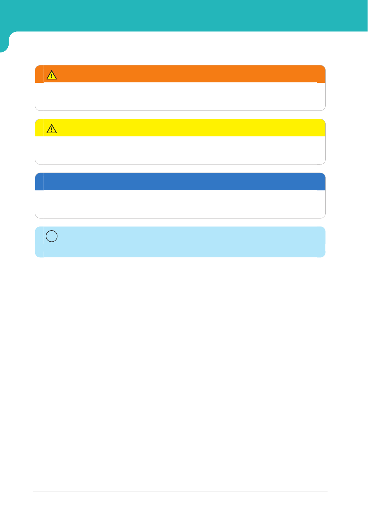
2.1 Safety information . . . . . . . . . . . . . . . . . . . . . . . . . . . . . . . . . . . . . . . . . . . . . . . . 14
3 System description 19
3.1 General description . . . . . . . . . . . . . . . . . . . . . . . . . . . . . . . . . . . . . . . . . . . . . . . 20
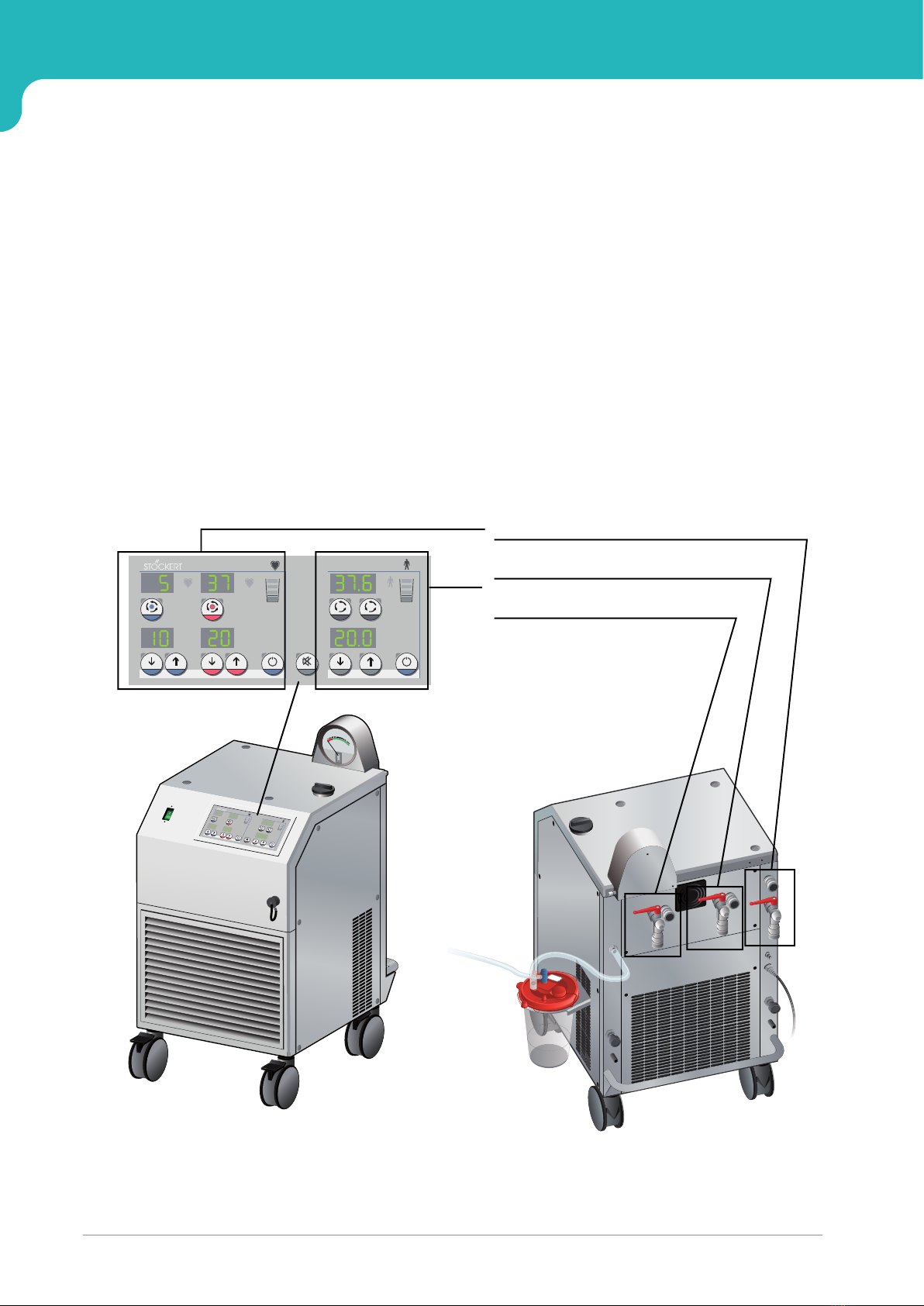
3.2 Structure of the heater-cooler . . . . . . . . . . . . . . . . . . . . . . . . . . . . . . . . . . . . . . . 25
4 Preparing the heater-cooler for a procedure 33
4.1 General technical requirements . . . . . . . . . . . . . . . . . . . . . . . . . . . . . . . . . . . . . 34
4.2 Conducting any required disinfection and maintenance . . . . . . . . . . . . . . . . . 36
4.3 Connecting the procedural tubing . . . . . . . . . . . . . . . . . . . . . . . . . . . . . . . . . . . 37
4.4 Connecting the potential equalization cable and the power supply . . . . . . . . 40
4.5 Connecting the aerosol collection set . . . . . . . . . . . . . . . . . . . . . . . . . . . . . . . . 42
4.6 Connecting to the S5/C5 System (if applicable) . . . . . . . . . . . . . . . . . . . . . . . . 49
4.7 Filling and mixing water tanks . . . . . . . . . . . . . . . . . . . . . . . . . . . . . . . . . . . . . . 50
5 Using the heater-cooler during a procedure 57
5.1 Positioning the heater-cooler in the OR . . . . . . . . . . . . . . . . . . . . . . . . . . . . . . . 58
5.2 Connecting the procedural tubing to external devices . . . . . . . . . . . . . . . . . . . 61
5.3 Powering on and checking the panel . . . . . . . . . . . . . . . . . . . . . . . . . . . . . . . . . 63
5.4 Performing a functional check prior to operation . . . . . . . . . . . . . . . . . . . . . . . 68
5.5 Priming the complete circuit . . . . . . . . . . . . . . . . . . . . . . . . . . . . . . . . . . . . . . . . 71
5.6 Using the device controls during a procedure . . . . . . . . . . . . . . . . . . . . . . . . . . 74
5.7 Completing a procedure . . . . . . . . . . . . . . . . . . . . . . . . . . . . . . . . . . . . . . . . . . . 80

Heater-Cooler System 3T • Table of contents
4CP_IFU_16-XX-XX_USA_023
6 Maintaining the heater-cooler 91
6.1 General maintenance precautions . . . . . . . . . . . . . . . . . . . . . . . . . . . . . . . . . . . 92
6.2 Maintenance schedule and checklists . . . . . . . . . . . . . . . . . . . . . . . . . . . . . . . 94
6.3 Cleaning and disinfecting external surfaces, connectors, and fittings . . . . . . 99
6.4 Disinfecting the water circuits every 14 days . . . . . . . . . . . . . . . . . . . . . . . . . 104
6.5 Monitoring the tank water . . . . . . . . . . . . . . . . . . . . . . . . . . . . . . . . . . . . . . . . 125
6.6 Changing the water and adding hydrogen peroxide . . . . . . . . . . . . . . . . . . . . 140
6.7 Preparing the heater-cooler for storage . . . . . . . . . . . . . . . . . . . . . . . . . . . . . . 148
6.8 Cleaning the heater-cooler interior . . . . . . . . . . . . . . . . . . . . . . . . . . . . . . . . . 150
6.9 Replacing the tubings once a year . . . . . . . . . . . . . . . . . . . . . . . . . . . . . . . . . . 152
7 Technical specifications 153
7.1 Specifications . . . . . . . . . . . . . . . . . . . . . . . . . . . . . . . . . . . . . . . . . . . . . . . . . . 154
7.2 Icons and labels . . . . . . . . . . . . . . . . . . . . . . . . . . . . . . . . . . . . . . . . . . . . . . . . 160
7.3 Part numbers . . . . . . . . . . . . . . . . . . . . . . . . . . . . . . . . . . . . . . . . . . . . . . . . . . . 164
7.4 Tested accessories . . . . . . . . . . . . . . . . . . . . . . . . . . . . . . . . . . . . . . . . . . . . . . 166
7.5 Warranty . . . . . . . . . . . . . . . . . . . . . . . . . . . . . . . . . . . . . . . . . . . . . . . . . . . . . . . 166
7.6 Information on electromagnetic compatibility (EMC)
according to IEC 60601-1-2 (4th edition) . . . . . . . . . . . . . . . . . . . . . . . . . . . . 167
8 Troubleshooting 175
8.1 Control panel warnings and error code displays . . . . . . . . . . . . . . . . . . . . . . . 176
8.2 Troubleshooting or returning the 3T Aerosol Collection Set . . . . . . . . . . . . . . 185

CP_IFU_16-XX-XX_USA_023 5
1 Introduction
This chapter provides an overview of
the device, including indications for
use and contraindications. This
chapter also provides an
explanation of each chapter,
technical terms and symbols used in
this operating manual, and a
definition of the filtered water
required for use in the heater-cooler.

Heater-Cooler System 3T • Introduction
Introduction
6CP_IFU_16-XX-XX_USA_023
1.1 Introduction
1.1.1 Device summary
The Heater-Cooler System 3T is an independent 3-circuit-heating/cooling system
which is suitable for continuous use.
The heater-cooler has three circuits that you control from the control display
panel:
●Cardioplegia circuit, whose temperature can be controlled from independent
heating and cooling tanks.
●Patient 1 circuit and patient 2 circuit, which can be used with the oxygenator
and/or the single-use heating/cooling blanket. The temperature for these two
circuits can be controlled from one heating/cooling tank.
The heater-cooler is a non-sterile device. No part of the heater-cooler is provided
sterile or can be sterilized.
0
20
40
TANKVACUUM
CALIBRATEDFOR
VERTICALPOSITION
MAXPRESSURE 100kPa
pascals
60
80
100
C
°
C°C°
C
°
C°
C°
12
C°C°C°
C°C°C°
12
Cardioplegia circuit
Patient 1 circuit
Patient 2 circuit
Control panel

Heater-Cooler System 3T • Introduction
Introduction
CP_IFU_16-XX-XX_USA_023 7
1.1.2 Indications for use
The Heater-Cooler System 3T is used to circulate water through heat exchangers to
warm or cool a patient during cardiopulmonary bypass procedures lasting 6 hours
or less.
1.1.3 Contraindications
There are no known contraindications for the Heater-Cooler System 3T. The
attending physician is solely responsible for the use of the system.
1.1.4 Legal disclaimer
LivaNova Deutschland GmbH will not assume any liability for any injuries and/or
damage to property caused by failure to observe the safety or operating
instructions or by failure to exercise due care. This also applies even if the duty to
exercise due care has not been expressly stated.
1.1.5 About these operating instructions
●These operating instructions are intended for clinical and maintenance
personnel, and provide instructions for using, operating, and maintaining the
Heater-Cooler System 3T.
●To ensure the safety of patients and the operators, read these operating
instructions thoroughly before using the heater-cooler for the first time.
●These operating instructions provide valuable information. They describe
operational steps and also contain information on how to avoid dangerous
situations and errors. These operating instructions also provide
troubleshooting instructions.

Heater-Cooler System 3T • Introduction
Introduction
8CP_IFU_16-XX-XX_USA_023
1.1.6 Symbols used in these operating instructions
NOTE: Provides additional information that can help you better understand a
specific instruction of function.
1Checkmark: Used to indicate an item to check before or after completing a task.
These items are for reference and do not replace detailed instructions.
WARNING
Indicates a hazardous situation that, if not avoided, could result in death or
serious injury.
CAUTION
Indicates a hazardous situation that, if not avoided, could result in minor or
moderate injury.
NOTICE
Indicates a hazardous situation that, if not avoided, may result in damage to the
device or other property.
Important
Indicates information considered important but not hazard related.
i

Heater-Cooler System 3T • Introduction
Introduction
CP_IFU_16-XX-XX_USA_023 9
1.1.7 The chapters in these operating instructions
1 Introduction
This chapter provides an overview of the device, including indications for use,
contraindications. This chapter also provides an explanation of each chapter,
technical terms and symbols used in this operating manual, and a definition of the
filtered water required for use in the heater-cooler.
2 Safety
This chapter provides general safety information that you must follow to ensure
safe and effective use. Additional safety information, such as Warnings and
Cautions, are included throughout the instructions in this manual.
3 System description
This chapter describes the system’s features and components, and the controls
that you will use to control the system’s circuits.
4 Preparing the heater-cooler for a procedure
This chapter provides instructions for preparing the heater-cooler for use.

Heater-Cooler System 3T • Introduction
Introduction
10 CP_IFU_16-XX-XX_USA_023
5 Using the heater-cooler during a procedure
This chapter provides instructions for positioning the heater-cooler in the OR and
using the heater-cooler’s controls during a procedure. This chapter also provides
the basic steps you will conduct after a procedure.
6 Maintaining the heater-cooler
This chapter provides instructions for the routine maintenance that is part of the
operating conditions for the heater-cooler. This applies to the routine
maintenance performed by the responsible organization as defined in IEC 60601-1
or the equivalent national standard, as well as to the preventive maintenance and
safety checks performed by LivaNova representatives or competent service
personnel.
7 Technical specifications
This chapter provides technical specifications including information about the
heater-cooler’s physical characteristics, labeling, part numbers, accessories, and
electromagnetic compatibility. This chapter also includes warranty information.
8 Troubleshooting
This chapter provides troubleshooting for warnings and error codes you might see
on the control panel, and troubleshooting related to the aerosol collection set.

Heater-Cooler System 3T • Introduction
Introduction
CP_IFU_16-XX-XX_USA_023 11
1.1.8 Terminology and abbreviations
Terminology
Abbreviations
Abbreviated term Full term
Heater-cooler Stöckert Heater-Cooler System 3T
S5 System Stöckert S5 System, modular heart-lung
machine
C5 System Sorin Compact 5 System, compact heart-
lung machine
Aerosol collection set 3T Aerosol Collection Set
Abbreviated term Full term
ACS Aerosol Collection Set 3T
AL Allowable Limit
CAN Controller Area Network (CAN bus)
cc Cubic centimeter (cm3)
CFU Colony Forming Unit
EMC Electromagnetic Compatibility
EPA Reg. No. Registration number of the United States
Environmental Protection Agency (applies
to the United States only)
HC3T Heater-Cooler System 3T
HLM Heart-Lung Machine
L Liters
LPM Liters per minute
mL Milliliters
NTM Non-tuberculous Mycobacteria
OR Operating Room
Pa Pascal
kPa Kilopascal
ppm Parts per million
RF Radio Frequency
UDI Unique Device Identifier

Heater-Cooler System 3T • Introduction
Introduction
12 CP_IFU_16-XX-XX_USA_023
1.1.9 Requirement for filtered tap water
Tap water used to fill the heater-cooler must be filtered using the following filter
and specifications:
Disposable Pall-Aquasafe water filter with an 0.2 μm membrane (Pall part
reference in the U.S.: “AQINA”; “AQIN” in other countries) or a filter of equivalent
performance that meets the requirements for bacterial retention of
Brevundimonas diminuta to ≥107CFU/cm2of effective filtration area.1
For instructions on filter management and disposal after the specified use period
please refer to the manufacturer’s instructions for use.
1 American Standard Test Method F838-15ae1 “Determining Bacterial Retention of Membrane
Filters Utilized for Liquid Filtration”

CP_IFU_16-XX-XX_USA_023 13
2 Safety
This chapter provides general safety
information that you must follow to
ensure safe and effective use.
Additional safety information, such
as Warnings and Cautions, are
included throughout the
instructions in this manual.

Heater-Cooler System 3T • Safety
Safety information
14 CP_IFU_16-XX-XX_USA_023
2.1 Safety information
2.1.1 General safety
●Read and understand the instructions for use before operating the heater-
cooler.
●Disinfect the external surfaces and water circuits per chapter 6 prior to first use.
●Do not place any objects (including the portable vacuum source) on top of the
heater-cooler.
●Maintain at least 70 cm clearance from walls and other devices while operating
the heater-cooler to prevent the heater-cooler from overheating.
●Do not operate the heater-cooler in the presence of explosive substances.
●Do not modify any of the mechanical or electrical systems of the heater-cooler.
●Do not remove the side or rear panels of the heater-cooler. Contact with the
internal components can cause serious injury or death.
●A list of approved accessory devices is contained in chapter 7. Do not use any
unapproved accessory devices with the heater-cooler.
●Do not use self-closing tubing connectors or connectors that incorporate a
valve. These connectors can reduce water flow to the external circuits.
●Drain heater-cooler water tanks outside the OR.
●Do not replace the aerosol collection canister in the OR environment.
●Avoid splashing heater-cooler water in the OR environment during use and
when making water circuit connections.
●Remove water spills from the OR floor using suitable disinfectants as
recommended by hospital procedures.
●Do not perform any maintenance activities while the heater-cooler is in use or
connected to an oxygenator or other heat exchanger device.

Heater-Cooler System 3T • Safety
Safety information
CP_IFU_16-XX-XX_USA_023 15
2.1.2 Information on diffusion of hydrogen peroxide
through the oxygenator heat exchanger
The water in the heater-cooler contains approximately 330 ppm of hydrogen
peroxide when prepared per these operating instructions. Contact the
manufacturer of the disposable oxygenator for information specific to the
hydrogen peroxide permeability of the heat exchanger for concentrations at or
below this level.
Do not use the heater-cooler with disposable oxygenators that have a heat
exchanger with a permeability rate that exceeds the daily allowable limit (AL) as
defined in the following table:
Although allowable limits (AL) for hydrogen peroxide diffusion are provided, actual
performance may vary in individual cases. Monitor and manage all patients.
Duration of
exposure to H202
Allowable limit (AL)
in mg/day per kg of
patient body
weight
Allowable mass of hydrogen peroxide
(H202) in mg/day the can be transferred
in patient blood for:
An adult
(typical body
weight is 60 kg)
A neonate
(typical body
weight is 3 kg)
Up to 6 hours 0.21 12.60 0.63
Over 6 hours 0.034 2.02 0.10

Heater-Cooler System 3T • Safety
Safety information
16 CP_IFU_16-XX-XX_USA_023
2.1.3 Procedural safety
●The heater-cooler does not monitor the temperature of the patient’s blood or
the cardioplegia solution.
●Do not empty the external circuits until the patient has been discharged from
the OR.
●LivaNova recommends always having a replacement heater-cooler available in
case the heater-cooler in use is no longer functional (e.g., due to a total system
failure). The replacement heater-cooler must have compatible connectors.
2.1.4 Electrical safety
●Do not modify any of the electrical systems of the heater-cooler.
●The heater-cooler should only be connected to a hospital-quality power source
with an integrated protective conductor (ground).
●To avoid the risk of electric shock, the heater-cooler must only be connected to
a supply mains with protective earth.
●Check the condition of the power cable and plug regularly and do not use the
heater-cooler if the cable or plug shows signs of wear or damage.
●Do not position the heater-cooler where it will block access to the mains power
plug. Removing the mains plug from the receptacle isolates the heater-cooler
from mains voltage and the plug must remain accessible at all times.
2.1.5 Integrating the HC3T into your facility
As part of the integration of the Heater-Cooler System 3T into your facility,
LivaNova strongly recommends the following:
●Ensure that all operators and maintainers of the heater-cooler read the
instructions and familiarize themselves with the use and maintenance of the
device (chapters 4, 5 and 6), with special emphasis on the critical tasks listed
in the table below.
●Integrate all maintenance activities listed in chapter 6.2.1 into your facility’s
preventative maintenance scheduling system. This includes the cleaning and
disinfection of the heater-cooler before first use. Failure to perform the
maintenance tasks as indicated can lead to bacterial growth inside the device
and an increased risk of exposing the patient to harmful bacteria.
●Implement regular bacterial sampling of the water in the heater-cooler into your
preventative maintenance scheduling system. This testing is critical to
understanding if the disinfection and water preservation activities are being
completed effectively. This testing can also indicate if an external source of
contamination (e.g. a contaminated water hose) is present.

Heater-Cooler System 3T • Safety
Safety information
CP_IFU_16-XX-XX_USA_023 17
If you have any questions about the integration of the Heater-Cooler System 3T
into your facility, please contact your LivaNova sales representative.
Human Factors Testing and clinical experience have shown that operators are
most likely to have issues understanding or performing the critical tasks in the
following table. This table provides the task description, where to locate the
instructions related to this task, and the consequences of failing to perform the
task correctly.
Task Location of
instructions
Potential consequences of incorrect task
performance or omission
Do not use the HC3T without
the ACS attached.
Chapter 4.5 Failure to use the ACS may result in the
emission of aerosol.
Cap unused ports on the ACS. Chapter 4.5
Task 3, 3
Failure to cap the tandem and pour ports
may lead to a loss of vacuum in the ACS,
potentially reducing the effectiveness in
preventing the emission of aerosol.
Write the installation date on
the ACS.
Chapter 4.5
Task 4, 7
Failure to write down the installation date
can lead to use of the ACS beyond 7 days,
potentially clogging the filter and reducing
the effectiveness in preventing the
emission of aerosol.
Replace the ACS after the
disinfection procedure.
Chapter 6.4.2
Task 11
Failure to replace the ACS after the
disinfection procedure could lead to
disinfectant vapor entering the vacuum
system.
Clean and disinfect the HC3T
prior to first use.
Chapter 6.2.1 Bacteria may be present on or in the heater-
cooler if the packaging was damaged
during transport or storage.
Disinfect the connectors and
tubing fittings prior to each
connection.
Chapter 6.3.2
Chapter 6.3.3
Failure to disinfect the connectors and/or
fittings could lead to bacterial growth that
can be transferred to other parts of the
heater-cooler or the OR.
Drain water tanks prior to
adding disinfectant.
Chapter 6.4.2
Task 2
Failure to drain the tanks prior to adding
disinfectant could reduce the
disinfectant’s effectiveness.
During disinfection, fill the
water tanks to the Patient level
second green LED after adding
disinfectant.
Chapter 6.4.2
Task 4, 4
Failure to completely fill the tanks during
disinfection could lead to a low level in one
tank, potentially resulting in incomplete
disinfection.
Circulate disinfectant by
pressing the WARM CP,
Patient 1, and Patient 2
buttons.
Chapter 6.4.2
Task 8, 1
Failure to circulate disinfectant using
Patient 1, Patient 2, and the WARM CP
buttons could lead to incomplete
disinfection of one or more tanks.

Heater-Cooler System 3T • Safety
Safety information
18 CP_IFU_16-XX-XX_USA_023
Do not use disinfectant during
a procedure.
Chapter 6.4.1 Use of disinfectant in the water during a
procedure could lead to failure of the
heater-cooler and the attached accessory
devices.
Mix chemicals (disinfectant or
hydrogen peroxide) by
connecting a tube between the
INLET of the CP circuit and the
INLET of the Patient 1 circuit.
Chapter 4.7
Task 3 & 4
Chapter 6.4.2
Task 6
Chapter 6.6
Task 4 & 5
Failure to properly connect the tubing prior
to mixing could lead to one or more tanks
not being exposed to the correct amount of
the chemical, potentially reducing the
effectiveness of the water preservation
process.
Mix chemicals (disinfectant or
hydrogen peroxide) using the
COLD CP button.
Chapter 6.4.2
Task 6, 1 and
Task 6, 2
Failure to use the COLD CP button to mix
disinfectant could result in insufficient
exposure of one or more tanks to the
required quantity of disinfectant.
Change the water in the heater-
cooler every 7 days.
Chapter 6.2.1
Section 6.6
Failure to change the water can lead to
ineffective prevention of bacterial growth.
Add 150 ml of 3% medical-
grade hydrogen peroxide when
filling the heater-cooler.
Chapter 4.7
Task 2, 3
Chapter 6.6
Task 3, 3
Failure to add hydrogen peroxide when
filling the water tanks can lead to
ineffective prevention of bacterial growth.
Performing the monthly
bacterial monitoring
procedure.
Chapter 6.5.2 Failure to properly sample the water in the
heater-cooler can lead to an inability to
identify potentially harmful levels of
bacterial growth in the device.
Task Location of
instructions
Potential consequences of incorrect task
performance or omission

CP_IFU_16-XX-XX_USA_023 19
3 System description
This chapter describes the system’s
features and components, and the
controls that you will use to control
the system’s circuits.

Heater-Cooler System 3T • System description
General description
20 CP_IFU_16-XX-XX_USA_023
3.1 General description
3.1.1 Device summary
The Heater-Cooler System 3T is an independent 3-circuit-heating/cooling system
which is suitable for continuous use.
The heater-cooler has three circuits that you control from the control display
panel:
●Cardioplegia circuit, whose temperature can be controlled from independent
heating and cooling tanks.
●Patient 1 circuit and patient 2 circuit, which can be used with the oxygenator
and/or the single-use heating/cooling blanket. The temperature for these two
circuits can be controlled from one heating/cooling tank.
0
20
40
TANKVACUUM
CALIBRATEDFOR
VERTICALPOSITION
MAXPRESSURE 100kPa
pascals
60
80
100
C
°
C°C°
C
°
C°
C°
12
C°C°C°
C°C°C°
12
Cardioplegia circuit
Patient 1 circuit
Patient 2 circuit
Control panel
Table of contents
Other LivaNova Medical Equipment manuals
Popular Medical Equipment manuals by other brands

Nonin
Nonin Avant 9700 Operator's manual

Otto Bock
Otto Bock 17KO1 Series Instructions for use

Univentor
Univentor 400 quick start guide

Jorvet
Jorvet Vet Pro Pump Maintenance & troubleshooting

natus
natus Madsen AccuScreen user manual

MHC Medical Products
MHC Medical Products SureLife Clearwave II user manual