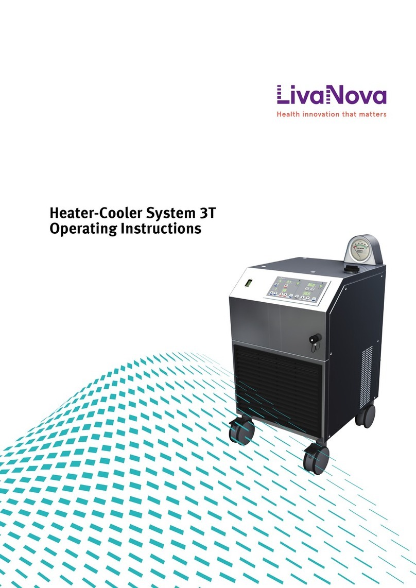
LivaNova SCP User manual

SCP System
Service Manual

CP_SEM_60-00-00.002
SCP System • Service Manual
Copyright © 2004 - 2017
LIVANOVA DEUTSCHLAND GMBH
TSSI Department
Lindberghstrasse 25
D-80939 Munich, Germany
HLM-Hotline: +49 89 41 61 26 461
Telephone: +49 - (0)89 - 32301-0
Telefax: +49 - (0)89 - 32301-777
All rights, particularly the right to reproduce, distribute and translate this manual, are reserved. No part of this
publication may be reproduced, stored electronically, processed, duplicated or distributed in any form – by photocopy,
microfilm or by any other means – without the written approval of LIVANOVA DEUTSCHLAND GMBH.
Service Manual
Version 02/2017– CP_SEM_60-00-00.002

SCP System • Table of contents
CP_SEM_60-00-00.002 3
Table of contents
1 Introduction
1.1 About this Service Manual . . . . . . . . . . . . . . . . . . . . . . . . . . . . . . . . . . . . . . . . . . . . . . . . . . . . . . . . . . . . . . . . .5
1.1.1 Symbols used in this Service Manual . . . . . . . . . . . . . . . . . . . . . . . . . . . . . . . . . . . . . . . . . . . . . . . . . . 5
1.1.2 The chapters in this Service Manual . . . . . . . . . . . . . . . . . . . . . . . . . . . . . . . . . . . . . . . . . . . . . . . . . . .6
2Safety
2.1 Approvals . . . . . . . . . . . . . . . . . . . . . . . . . . . . . . . . . . . . . . . . . . . . . . . . . . . . . . . . . . . . . . . . . . . . . . . . . . . . . . 7
2.2 Regulations and safety instructions . . . . . . . . . . . . . . . . . . . . . . . . . . . . . . . . . . . . . . . . . . . . . . . . . . . . . . . . . 7
2.2.1 Usage in accordance with regulations. . . . . . . . . . . . . . . . . . . . . . . . . . . . . . . . . . . . . . . . . . . . . . . . . . 7
2.2.2 General safety instructions . . . . . . . . . . . . . . . . . . . . . . . . . . . . . . . . . . . . . . . . . . . . . . . . . . . . . . . . . .8
2.2.3 Operating safety . . . . . . . . . . . . . . . . . . . . . . . . . . . . . . . . . . . . . . . . . . . . . . . . . . . . . . . . . . . . . . . . . . . 9
2.2.4 Electrical safety. . . . . . . . . . . . . . . . . . . . . . . . . . . . . . . . . . . . . . . . . . . . . . . . . . . . . . . . . . . . . . . . . . . 10
2.2.5 Safety instructions for routine maintenance. . . . . . . . . . . . . . . . . . . . . . . . . . . . . . . . . . . . . . . . . . . . 10
2.3 Safety features of the device . . . . . . . . . . . . . . . . . . . . . . . . . . . . . . . . . . . . . . . . . . . . . . . . . . . . . . . . . . . . . . 10
3 System description
3.1 SCP System . . . . . . . . . . . . . . . . . . . . . . . . . . . . . . . . . . . . . . . . . . . . . . . . . . . . . . . . . . . . . . . . . . . . . . . . . . . . 11
3.1.1 SCP System components . . . . . . . . . . . . . . . . . . . . . . . . . . . . . . . . . . . . . . . . . . . . . . . . . . . . . . . . . . . 11
3.1.2 Overview . . . . . . . . . . . . . . . . . . . . . . . . . . . . . . . . . . . . . . . . . . . . . . . . . . . . . . . . . . . . . . . . . . . . . . . . 12
3.2 Service-relevant modules . . . . . . . . . . . . . . . . . . . . . . . . . . . . . . . . . . . . . . . . . . . . . . . . . . . . . . . . . . . . . . . .14
3.2.1 Module overview - Pump control panel . . . . . . . . . . . . . . . . . . . . . . . . . . . . . . . . . . . . . . . . . . . . . . . . 15
Display board (ZPA 9908). . . . . . . . . . . . . . . . . . . . . . . . . . . . . . . . . . . . . . . . . . . . . . . . . . . . . . . . . . . 16
CPU board (ZKR 9910) . . . . . . . . . . . . . . . . . . . . . . . . . . . . . . . . . . . . . . . . . . . . . . . . . . . . . . . . . . . . . . 18
Flow sensor board (DIGIFLOW) . . . . . . . . . . . . . . . . . . . . . . . . . . . . . . . . . . . . . . . . . . . . . . . . . . . . . . . 19
3.2.2 Module overview - Drive unit . . . . . . . . . . . . . . . . . . . . . . . . . . . . . . . . . . . . . . . . . . . . . . . . . . . . . . . .20
Motor control board (ZPR 9909 A) . . . . . . . . . . . . . . . . . . . . . . . . . . . . . . . . . . . . . . . . . . . . . . . . . . . . 21
3.2.3 Functional diagram of flow probe . . . . . . . . . . . . . . . . . . . . . . . . . . . . . . . . . . . . . . . . . . . . . . . . . . . .22
4 Error messages and error diagnosis
4.1 Error messages . . . . . . . . . . . . . . . . . . . . . . . . . . . . . . . . . . . . . . . . . . . . . . . . . . . . . . . . . . . . . . . . . . . . . . . . .25
4.1.1 Non-specific error displays and operating errors . . . . . . . . . . . . . . . . . . . . . . . . . . . . . . . . . . . . . . . . 25
4.1.2 Error codes. . . . . . . . . . . . . . . . . . . . . . . . . . . . . . . . . . . . . . . . . . . . . . . . . . . . . . . . . . . . . . . . . . . . . . .26

SCP System • Table of contents
4CP_SEM_60-00-00.002
5 Replacing components
5.1 Pump control panel . . . . . . . . . . . . . . . . . . . . . . . . . . . . . . . . . . . . . . . . . . . . . . . . . . . . . . . . . . . . . . . . . . . . .29
5.1.1 Opening the pump control panel . . . . . . . . . . . . . . . . . . . . . . . . . . . . . . . . . . . . . . . . . . . . . . . . . . . . .29
Operating with the S5/C5 or the S3/SC System . . . . . . . . . . . . . . . . . . . . . . . . . . . . . . . . . . . . . . . . .29
5.1.2 Replacing pump control panel components . . . . . . . . . . . . . . . . . . . . . . . . . . . . . . . . . . . . . . . . . . . . 31
EPROM . . . . . . . . . . . . . . . . . . . . . . . . . . . . . . . . . . . . . . . . . . . . . . . . . . . . . . . . . . . . . . . . . . . . . . . . . . 31
CPU board (ZKR 9910) . . . . . . . . . . . . . . . . . . . . . . . . . . . . . . . . . . . . . . . . . . . . . . . . . . . . . . . . . . . . . .32
Display board (ZPA 9908) . . . . . . . . . . . . . . . . . . . . . . . . . . . . . . . . . . . . . . . . . . . . . . . . . . . . . . . . . . .33
Flow sensor board (DIGIFLOW) . . . . . . . . . . . . . . . . . . . . . . . . . . . . . . . . . . . . . . . . . . . . . . . . . . . . . . .34
Connecting cable and/or mains filter . . . . . . . . . . . . . . . . . . . . . . . . . . . . . . . . . . . . . . . . . . . . . . . . .35
Dismantling the shaft angle encoder (SAE) . . . . . . . . . . . . . . . . . . . . . . . . . . . . . . . . . . . . . . . . . . . . .37
Assembling the shaft angle encoder . . . . . . . . . . . . . . . . . . . . . . . . . . . . . . . . . . . . . . . . . . . . . . . . . .38
5.2 Drive unit . . . . . . . . . . . . . . . . . . . . . . . . . . . . . . . . . . . . . . . . . . . . . . . . . . . . . . . . . . . . . . . . . . . . . . . . . . . . . .39
5.2.1 Opening the drive system. . . . . . . . . . . . . . . . . . . . . . . . . . . . . . . . . . . . . . . . . . . . . . . . . . . . . . . . . . .39
5.2.2 Replace drive unit components . . . . . . . . . . . . . . . . . . . . . . . . . . . . . . . . . . . . . . . . . . . . . . . . . . . . . .40
Motor control board (ZPR 9909 A) . . . . . . . . . . . . . . . . . . . . . . . . . . . . . . . . . . . . . . . . . . . . . . . . . . . .40
Connecting cable. . . . . . . . . . . . . . . . . . . . . . . . . . . . . . . . . . . . . . . . . . . . . . . . . . . . . . . . . . . . . . . . . .42
6Appendix
6.1 Technical data . . . . . . . . . . . . . . . . . . . . . . . . . . . . . . . . . . . . . . . . . . . . . . . . . . . . . . . . . . . . . . . . . . . . . . . . .45
6.1.1 Dimensions, weights, operating conditions . . . . . . . . . . . . . . . . . . . . . . . . . . . . . . . . . . . . . . . . . . . .45
6.1.2 Electrical specifications . . . . . . . . . . . . . . . . . . . . . . . . . . . . . . . . . . . . . . . . . . . . . . . . . . . . . . . . . . . .46
6.1.3 General data . . . . . . . . . . . . . . . . . . . . . . . . . . . . . . . . . . . . . . . . . . . . . . . . . . . . . . . . . . . . . . . . . . . . .46
6.2 Labelling . . . . . . . . . . . . . . . . . . . . . . . . . . . . . . . . . . . . . . . . . . . . . . . . . . . . . . . . . . . . . . . . . . . . . . . . . . . . . .47
6.3 Part numbers, standard components and accessories . . . . . . . . . . . . . . . . . . . . . . . . . . . . . . . . . . . . . . . . 48
6.4 Accessories . . . . . . . . . . . . . . . . . . . . . . . . . . . . . . . . . . . . . . . . . . . . . . . . . . . . . . . . . . . . . . . . . . . . . . . . . . . 48
6.5 Service component part numbers . . . . . . . . . . . . . . . . . . . . . . . . . . . . . . . . . . . . . . . . . . . . . . . . . . . . . . . . . .49
6.5.1 Pump control panel . . . . . . . . . . . . . . . . . . . . . . . . . . . . . . . . . . . . . . . . . . . . . . . . . . . . . . . . . . . . . . . .49
6.5.2 Drive unit . . . . . . . . . . . . . . . . . . . . . . . . . . . . . . . . . . . . . . . . . . . . . . . . . . . . . . . . . . . . . . . . . . . . . . . .50

SCP System • Introduction
CP_SEM_60-00-00.002 5
1 Introduction
1.1 About this Service Manual
This Service Manual (in addition to the training courses run by LIVANOVA DEUTSCHLAND GMBH) is the
basis for the maintenance and repair of your SCP System. This manual is intended only for suitably
qualified service technicians. In the interest of the safety of patients and all operators:
!
Only service technicians trained and authorised by LIVANOVA DEUTSCHLAND GMBH may service the
SCP System.
Please refer to the operating instructions for any information you need on operating the SCP System.
This Service Manual contains references to the corresponding chapters in the operating instructions (if
required).
1.1.1 Symbols used in this Service Manual
The symbols used in this manual are intended to help you find special text passages. The meaning of
the symbols is as follows:
!Danger! Failure to pay attention may endanger the patient’s and/or
the operator’s life.
!Warning! Failure to pay attention may cause damage to the machine
or other equipment.
✓A check list for a quick and safe follow up on whether operational
steps have been carried out completely.
◗Primary list (main groups)
➜Secondary list (subgroups)

SCP System • Introduction
6CP_SEM_60-00-00.002
1.1.2 The chapters in this Service Manual
In chapter... you will find the following information:
1 Introduction ➜Symbols used in the Service Manual
➜Overview of chapters (this table)
2Safety ➜Important safety instructions for the
operation of the SCP System
3Systemdescription ➜A brief description of all the service-
relevant components
4 Error messages and error diagnosis ➜A list of all error messages and
information on locating errors
5 Replacing components ➜Information and instructions on the
removal and installation of components
6Appendix ➜Technical data on all components
➜Part numbers/spare parts

SCP System • Safety
CP_SEM_60-00-00.002 7
2Safety
2.1 Approvals
Just as for development and production, the system must also be serviced in accordance with the
following standards and legal regulations.
2.2 Regulations and safety instructions
2.2.1 Usage in accordance with regulations
!
◗The SCP System is solely intended for use with the Revolution®on and/or with a Stöckert/
Sorin HLM (S3/SC/S5/C5) or the SCPC System as a centrifugal pump during cardiopulmonary
bypass. Any use beyond this specification is not in accordance with the regulations and
LIVANOVA DEUTSCHLAND GMBH will not assume any liability for damage in such a case. Usage in
accordance with regulations also includes compliance with the operating instructions, as well as
repair and maintenance according to the maintenance instructions.
◗Relevant accident prevention measures according to existing local policy and employees’ health
and safety regulations must be complied with. LIVANOVA DEUTSCHLAND GMBH will not assume
any liability for damage due to non-compliance with these regulations.
◗LIVANOVA DEUTSCHLAND GMBH will not assume any liability for injuries and/or damage caused by
failure to observe the safety instructions or by the operator not taking due care. This applies even if
the operator’s duty to take due care has not been specifically expressed to the user.
IEC 62353 – Recurrent test and test after repair of
medical electrical equipment
IEC 60601-1-2 – EMC (Electromagnetic Compatibility)
MDD – Medical Device Directive 93/42 EEC
DIN EN ISO 13485 – Quality Management System
UVV – Regulations for Accident Prevention
UL 2601-1 – Standard for Medical and Dental
Equipment
GMP – Good Manufacturing Practice

SCP System • Safety
8CP_SEM_60-00-00.002
2.2.2 General safety instructions
◗The SCP System has been designed according to current state-of-the art technology and accepted
safety standards. Although this may be the case, danger may arise for the patient, the user or for
other equipment during operation.
◗The SCP System must be operated and maintained by trained and qualified personnel only.
!
◗The SCP System must not be operated near explosive substances.
Usage in accord-
ance with regula-
tions: See page 7.
◗The SCP System may only be used when in fully operational condition and according to regulations
and the operating instructions.
◗The operating instructions must be available close to the SCP System at all times. Incomplete or
illegible operating instructions must be replaced immediately.
◗According to the European Directive 93/42 EEC and the national standards based on this directive,
the SCP System must be subjected to a regular maintenance checks by an authorised service
representative. The maintenance check for the SCP System must be performed after every
1000 operating hours or at least once every 12 months (whichever comes first).
◗In addition to the operating instructions, the relevant legal, general and binding regulations
concerning the prevention of accidents must be observed.
◗In order to take situations into account which are clinic-specific and outside of normal routines,
e.g. certain working procedures, the operating instructions must be supplemented with relevant
instructions (supervision and registration requirements, etc).
◗Personnel operating the SCP System must have acquainted themselves thoroughly with the
operating instructions prior to working with the machine.
◗If you discover any safety-relevant modifications to the SCP System or its operating behaviour
(outside of OP mode): Do not use the device and have it checked out by authorised service
personnel.
◗Do not perform any modifications or extensions to the device, unless they have been tested and
approved by LIVANOVA DEUTSCHLAND GMBH. LIVANOVA DEUTSCHLAND GMBH cannot otherwise
give any guarantee or assume liability.
◗Keep the device clean. Doing so will prevent possible contact errors and faults due to dirt.

SCP System • Safety
CP_SEM_60-00-00.002 9
2.2.3 Operating safety
◗Prior to working with the SCP System, you must have thoroughly read the operating instructions
and have become familiar with the machine functions.
!
◗The SCP System may only be used with the Revolution®.
◗Prior to mounting the Revolution®, you must have thoroughly read the separate operating
instructions and have become familiar with the machine functions.
◗For safety reasons, always have a spare Revolution®
available.
◗Please note that the SCP drive unit must be positioned at ≤ 45° to vertical (see operating
instructions).
!
◗Prior to operation, check all cables, tubing, connectors and other accessories to ensure correct
connections, seals and proper function. Replace all damaged components immediately.
!
◗The SCP System may only be operated under constant supervision. Failure to comply with this
obligation can result in danger to the patient. The safety features of the SCP System (alarm signals,
etc.) provide support, but are no replacement for the operator.
◗The SCP System must not be operated in master-slave mode in conjunction with an S3/SC roller
pump.
◗Ensure that the tubing is straight and do not kink or twist the cables. Kinked or twisted cables can
pose a hazard for personnel (causing them to stumble or catch on the tubing).
!
◗For safety reasons, always have a haemostat/surgical clamp available and ensure that the arterial
line is accessible when operating the electrical remote-controlled tubing clamp.
◗Prior to operating the tubing clamp, the user must have thoroughly read the operating instructions
and have become familiar with the device functions.
◗For the flow sensor, use only PVC tubes with a diameter of 3/8" x 3/32".
◗Do not connect the flow sensor until you have read the separate operating instructions.
◗Ensure optimum ventilation at the ventilation grills and the fan. Insufficient ventilation may result
in excessive heating.
◗The SCP connection cable, the cable of the drive unit and the cable of the flow sensor must be
equipped with blocking ferrites.
◗Modifications or extensions to the machine, as well as the use of spare parts, which have not been
tested and approved by LIVANOVA DEUTSCHLAND GMBH, may have negative effects on the safety
and function of the machine. LIVANOVA DEUTSCHLAND GMBH cannot accept any liability or
responsibility.
!
◗For safety reasons, keep the SCP emergency drive unit ready for use and familiarise yourself with
the mounting and functioning of the emergency drive unit.
◗Use only as many connectors, tubes, etc., in the tubing system use are necessary for operation in
accordance with the regulations. Additional couplings, etc., increase the risk of faults.
◗Accessories and supplementary devices, which have not been tested and approved by
LIVANOVA DEUTSCHLAND GMBH, must prove that their use does not pose a safety hazard.

SCP System • Safety
10 CP_SEM_60-00-00.002
2.2.4 Electrical safety
◗Electrical installations must comply with DIN VDE 0107 (for Germany) or the corresponding,
equivalent, local regulations and guidelines. Refer to the technical specifications in this respect.
◗The pump control console must be totally powered down when switching on or off the SCP drive
unit.
◗Check the functional safety of all electrical connections, cables and sockets regularly.
2.2.5 Safety instructions for routine maintenance
◗Routine maintenance work must only be performed by qualified personnel.
!
◗Disconnect the device from the power supply completely before carrying out maintenance and
cleaning work.
◗Please adhere to the service and maintenance instructions given in these operating instructions as
well as the recommended maintenance intervals.
◗Ensure that no liquids or cleaning agents enter the machine housing through the vents or other
openings.
◗Use recommended cleaning agents.
◗Repair work may only be carried out by authorised service technicians. Only original spare parts
from LIVANOVA DEUTSCHLAND GMBH may be used in order to guarantee the proper functioning of
the device.
2.3 Safety features of the device
◗The SCP System performs a self-test during power-up. Check that all the LEDs, the 7-segment
displays and the beep alarm function correctly.
◗Visual and audible alarms indicate when an internal error has occurred.

SCP System • System description
CP_SEM_60-00-00.002 11
3 System description
3.1 SCP System
Either a Stöckert/Sorin HLM (S3/SC/S5/C5) or the SCPC system is required to operate or supply the
current for the SCP System. The following pages provide an overview of each of the components.
3.1.1 SCP System components
The SCP System consists of the following components:
◗Pump control panel ➜Operation and configuration of the
SCP System
◗Drive unit ➜Revolution®drive by magnetic coupling
◗Emergency drive unit ➜Manual drive unit for Revolution®
◗Flow sensor ➜Measurement of blood flow and detection
of bubbles

SCP System • System description
CP_SEM_60-00-00.002 13
Fig. 2: Diagram of the SCP System
ZPA 9908 ZKR 9910 DIGIFLOW
24V
24V
5V
A 2
A 9
A 3
A 4
A 5
A
Mod. Components contains the following service-relevant modules/components:
APump control panel ◗Display board ZPA 9908 (A 3)
◗CPU board ZKR 9910 (A 4)
◗Flow sensor board DIGIFLOW (A 5)
◗Shaft angle encoder (A 2)
◗Fan
◗HLM/SCPC connecting cable (A 9)
See „Module overview
- Pump control panel“
on page 15.
BDrive unit ◗Motor control board ZPR 9909 A
◗Pump control panel connecting cable
CEmergency drive unit ◗None. In the event of a defect, replace the emergency drive
unit.
DFlow sensor ◗None. In the event of a defect, replace the flow sensor.

SCP System • System description
14 CP_SEM_60-00-00.002
3.2 Service-relevant modules
As is apparent from the previous list of components, not all the modules in the SCP System can be
repaired individually on site. Please consider the following before starting to service the system:
Pump control panel
On-site repairs can be performed by replacing boards or individual modules (e.g. shaft angle encoder,
connecting cable). Service work on the boards themselves is not performed on site. The only exception
to this is the replacement of the EPROM with the firmware necessary for operation (update).
Drive unit
Adjustment of the mechanical components requires precision tools and test instruments that are not
available to the on-site service team. The following errors therefore cannot be eliminated directly and
require the replacement of the whole drive unit:
◗Defective motor
◗Defective Hall sensor
◗Mechanical errors (e.g. warehouse damage, unusual operating noises)
Emergency drive unit
The same restrictions apply to the emergency drive unit as to the drive unit; mechanical repairs and
adjustment operations are not possible on site. The board for the speed display is only accessible after
the drive unit mechanism has been partially disassembled, so that in this case also it is not possible to
replace the board. Always therefore replace a defective emergency drive unit completely.
Flow sensor
The sensor does not contain any components that can be repaired and that are accessible for
servicing. Always therefore replace a defective flow sensor completely.

SCP System • System description
CP_SEM_60-00-00.002 15
3.2.1 Module overview - Pump control panel
Fig. 3: Module overview of the pump control panel
A 3
A 1
A 6
A 2
A 4
A 5
A 7
A 8
A 10
Mod. Item Description Number SP number
A1Upper casing
with adhesive foil
75-521-101
76-102-941
A2Shaft angle encoder with rotary knob and
assembly parts
see page 37
A3Display board with pusher caps ZPA 9908 see page 33
A4CPU board ZKR 9910 90-305-190
A5Flow sensor board DIGIFLOW 90-900-520
A6Lower casing 75-521-102
A7Mains filter 96-401-012
A8Toggle switch 96-121-209
A9Connecting cable to E/P pack, S3
Connecting cable to E/P pack, S5
(not kinked, firmly attached)
97-102-616
97-102-626
A10Holder (complete) for control panel 60-02-13

SCP System • System description
CP_SEM_60-00-00.002 17
Mod. Item Description Number Remark
A117-segment display Flow
A12LED bar graph display Flow
A13LEDs (arrows) Flow
A14LED Bubble Detector
A15LED Level Monitoring
A167-segment display Pressure
A17LEDs Pressure Unit
A18LED (arrow) Pressure
A197-segment display Actual Value (speed)
A20Auto key with with pusher cap (grey)
A21Audio Alarm Off key with pusher cap (grey)
A22Menu key with pusher cap (grey)
A23Clamp closed key with pusher cap (grey)
A24Clamp open key with pusher cap (grey)
A25Low RPM key with pusher cap (grey)
A26LED bar graph display Actual Value (speed)
A27Connector to CPU board
A28Fan

SCP System • System description
18 CP_SEM_60-00-00.002
CPU board (ZKR 9910)
Fig. 5: CPU board
A 31
A 34
A 32
A 33
A 37
A 38
A 30
A 35
A 36
A 29
Mod. Item Description Number Remark
A29DIP switch (2 pole) S1 on ZKR 9910 C and
later
A30Connector to display board CON 3
A31CAN/24V connection CON 1
A32Drive unit connection CON 2
A33Shaft angle encoder connection CON 4
A34Flow sensor board connection CON 5
A35Flow sensor, +24V board connection CON 6
A36Flow sensor, 0V board connection CON 7
A37Processor/CPU 80C196 KC X 63
A38EPROM (firmware) X 62

SCP System • System description
CP_SEM_60-00-00.002 19
Flow sensor board (DIGIFLOW)
Fig. 6: Flow sensor board
A 39
A 41
A 40
A 42
Mod. Item Description Number Remark
A39Flow sensor connection (D-Sub 9f) P2 not used
A40CPU board connection J2
A41Current supply +24V/0V connection J3
A42Flow sensor cable 97-101-898

SCP System • System description
20 CP_SEM_60-00-00.002
3.2.2 Module overview - Drive unit
Fig. 7: Module overview - Drive unit
B 2
B 4
B 1
B 6
B 7
B 3
B 5
Mod. Item Description Number SP number
B1Drive casing with motor
B2Base plate
see page 50 for
details
B3Splash protection with
B4Slide bearing
B5Motor control board ZPR 9909 A 90-305-185
B6Connecting cable to pump control panel 97-102-615
B7Countersunk head screw (slotted), DIN 963, M3x8
This manual suits for next models
1
Table of contents
Other LivaNova Medical Equipment manuals