GT1-1.6~3.3kW
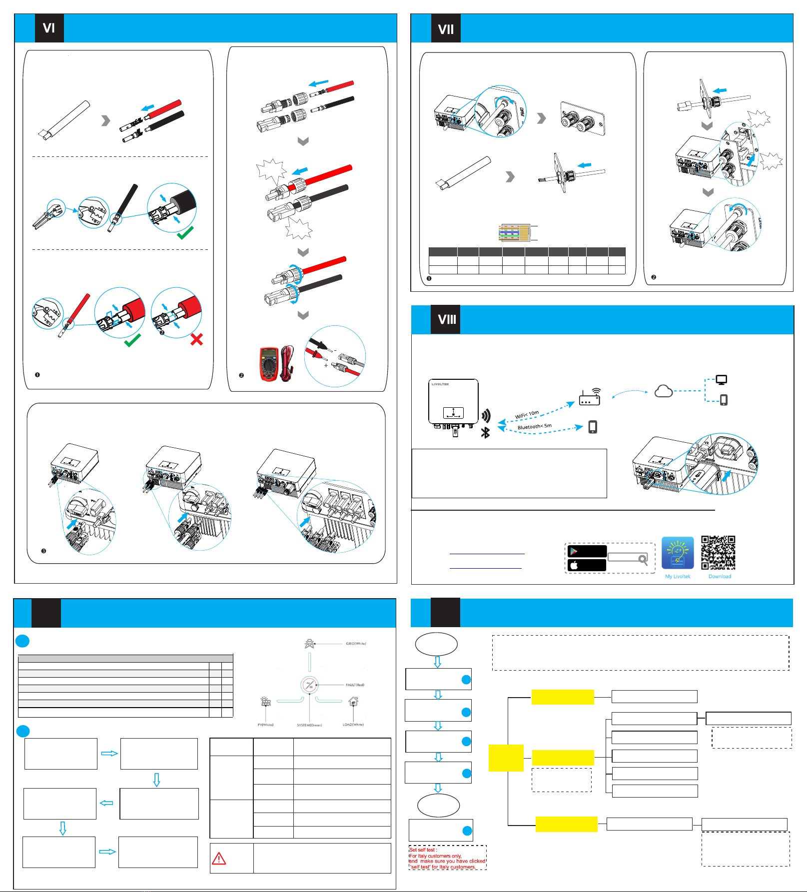
- Step6:Plug into inverter PV port
ⅨPowering on/off the Inverter
-Wire diameter:12AWG;
-Step1:Stripping:5~7mm;
- Step4:Through the PV terminal
- Step5:Measure the PV+/PV- voltage(<600V)
-Step3:Use crimping pliers to crimp it
Wi-Fi Dongle Connection
PV Connection
02
GT1-3.6~6.0kW GT1-7.0~10.0kW
-Step2:Insert the PV+/PV- pin respectively;
5.00~7.00 mm
MC4 crimping
tool
- PV+ crimping method:
- PV- crimping method:
Step1 Step2
Step3
Step3
Negative
Positive
Click!
Click!
<600 V
Communication Connection
-Prepare the connector and the communication cable,following the PIN
denition and assembly order below ,then insert the cable into the
corresponding RS485 port of the inverter, and tighten the waterproof
(Torque:1.2±0.1N·m)
PIN
Meter
1 4 7 5 8 2 3 6
DRM
485A2 485B2
XXXXX X
-Step1:Unscrew the screw and take o ffthe cover;
-Step2:Pass the wire harness through the cover with the waterproof plug;
-Step3:and then strip the wire. Stripping requirements: 5~7mm.
-Step5:Correspondingly insert the DRM\Meter port;
-Step6:lock the cover.
Note: For the detailed introduction of DRM and
smart meter of external communication equipment,
please refer to chapter 6.3 of the manual.
DRM1/5 DRM2/6 DRM3/7 DRM4/8 3.3V DRM0 3.3V GND
1
8
...
7
6
8
5.00~7.00 mm
Step1 Step2
Step3 Step4
connector.
Step5
Step6
Step7
Click!
Click!
Initial Parameter Setting
Ⅹ
Server
Wi-Fi Dongle Connection Steps:
Step 1 Remove the waterproof lid from the Wi-Fi/4G terminal.
Step 2 Insert the Wi-Fi Dongle into the communication port.
Step 3 Build the connection between the Wi-Fi dongle and home
WiFi router by our livoltek App local mode.
Refer the App guide manual delivered with the product or find it at our
App homepage 'guide' (please install 'My Livoltek' APP on your phone firstly)
‘My Livoltek' is a platform to communicate with your device via WiFi or bluetooth, you can login on our web(link as below) on your
computer, also you can scan the QR code to download the APP on your phone.
Google Play
App Store
Mylivoltek
APP: Search for My Livoltek on Apple App Store, Google Play.
WEB LINK1 :
https://www.livoltek-portal.com/
For Asia, Latin
American, Australia and others
WEB LINK2 :
https:// .livoltek-portal.com/evs
For Europe,
Middle East Regions, Africa
A Inspection before Commissioning
No. Content
1 All the switches connected to the inverter are set to the OFF position. Yes No
2 The inverter is installed correctly and securely.
3 All cables are connected correctly and securely.
4 Unused cable holes are fitted using the waterproof nuts.
5 The Wi-Fi Dongle is installed correctly and securely.
6 The electrical conduit holes are sealed.
State
7The smart meter is connected.
Start Guide
Step 1
Turn on the AC breaker
on the GRID side.
Step 2
Step 3
.
Step 6
Observe the
LED indicator.
Step 4
.
Step 5
Wi-Fi
Dongle
connection.
B Powering on the System
Note: The shutdown steps are opposite to the above order.
Switch on the loads
Color Status Description
Green
Red
On
Off
On
Off
Blink
The inverter is running normally
Other statuses except Running
Fault occurs
No fault occurs
Fault occurs
WARNING
.
1. Power on inverter
2. Install My Livoltek App
3. Wi-Fi dongle connection by App
4. App Account Restration
Steps:
5. Creat a site(Plant)
6. Add the device(inverter,EV Charger)to the site
7. Initial parameter setting by App local mode.
8. Run
Start
Set Date Time
Advanced
Settings
End
1
2
1
1
1
1
3
4
Basic Settings
Advanced Settings
Date & Time
Grid Protection Prameters
Active Power Adjustment
Reactive Power Adjustment
Feature Parameters
Installation Setup
Feed-in Limitation
Grid Standards
Disable/ Chint single Feed-in Power Limit Value
Only qualified installers are
permitted to set the advanced
with a password ‘hx123456'.
Check or select the country
safety standards where the
inverter is installed.
To control the amount of power
injected in the grid.This function
requires
Meter. Otherwise,this function will
be unavailable.
Setting
via APP
local mode
Set Self test
System updating
Blink
Rotate the DC switch of
the inverter to ON position.
Turn on DC breaker
Set Feed-in
Limitation
Set Grid
Standards
(Optional)
5
the using of Smart Energy
Before maintaining and commissioning inverter and its
peripheral distribution unit switch off all the charged
terminals of the inverter, and wait at least 10 minutes
after the inverter is powered off.
You can use the following communication modes to implement communication: Bluetooth and Wi-Fi, The Wi-Fi with
built-in Bluetooth module for local monitoring and managing. all of which are described as follows:
Monitoring module connection diagram:
setting,the setting is protected


