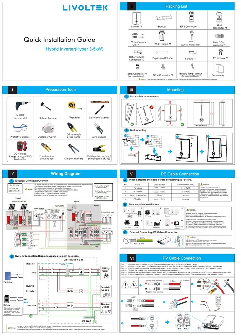
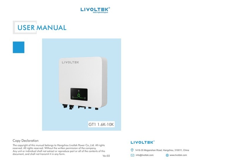
LIVOLTEK Hyper 3000 User manual

USER
MANUAL
Hyper 3~5kW
Copyright Declaration
The copyright of this manual belongs to Hangzhou Livoltek Power Co., Ltd. Any
corporation or individual should not plagiarize, partially or fully copy and no reproduction
or distribution of it in any form or by any means. All rights reserved.
HP16521-Ver 10-2204

Content
1. About This Manual............................................................................. 4
1.1 Validity ..................................................................................4
1.2 Target Group .........................................................................4
1.3 Symbol Used..........................................................................4
1.4 Storage of the manual...........................................................4
2. Safety Precautions .............................................................................5
2.1 Personnel Requirements....................................................... 5
2.2 Inverter Safety.......................................................................5
2.3 Battery Safety........................................................................6
2.4 Installation Safety..................................................................7
2.5 Electrical Safety .....................................................................7
2.6 Maintenance and Replacement ............................................8
3. Product Introduction .........................................................................9
3.1 Function Description .............................................................9
3.2 Appearance ......................................................................... 10
3.3 System Diagram .........................................................................12
3.4 Work Modes............................................................................... 13
4. Unpacking and Storage....................................................................17
4.1 Packing List................................................................................. 17
4.2 Identify the Inverter ...................................................................19
5. Mechanical Installation....................................................................22
5.1 Installation Requirements.......................................................... 22
5.2 Installation Instruction ............................................................... 24
6. Electrical Connection .......................................................................31
6.1 Wiring Diagram ..........................................................................32
6.2 Additional Grounding Connection..............................................34
6.3 Grid Cable Connection ...............................................................35
6.4 Critical Loads Connection (EPS function) ...................................37

6.5 PV Cable Connection..................................................................39
6.6 Battery Connection ....................................................................41
6.7 WIFI / 4G Connection (Optional)................................................45
6.8 DRM Connection ........................................................................ 46
6.9 Multi COM Terminal Connection ...............................................47
6.10 Installation Verification ............................................................ 53
7. System Operation ............................................................................54
7.1 LEDs Display ...............................................................................54
7.2 System Commissioning .............................................................. 56
7.3 System Decommissioning...........................................................57
8. Settings on the APP..........................................................................58
8.1 User Interface Introduction........................................................58
8.2 Download and Install.................................................................. 59
9. Troubleshooting and Maintenance .................................................60
9.1 Troubleshooting .........................................................................60
9.2 Maintenance ..............................................................................62
9.3 Removing the Inverter ............................................................... 63
9.4 Disposal of the Inverter............................................................. 63
10. Technical Data ................................................................................. 64
11. Disclaimer...........................................................................................66

4
1. About This Manual
1.1 Validity
Thank you for choosing our low-voltage hybrid inverter. This manual is valid for the
following models:
Hyper 3000, Hyper 3680, Hyper 4600, Hyper 5000
1.2 Target Group
This manual is intended for qualified persons and inverter owners. All activities
described in the document may only be carried out by specially trained personnel in
compliance with standards, wiring rules and the requirements of local grid authorities or
companies. Moreover, they must also understand basic safety precautions and with the
knowledge of how to deal with the dangers and risks associated with installing, repairing
and using electrical devices and batteries.
1.3 Symbol Used
Safety instructions will be highlighted with the following symbols.
Symbol
Description
Indicates a hazard with a high level of risk that, if not
avoided, will result in death or serious injury.
Indicates a hazard with a medium level of risk that, if not
avoided, could result in death or serious injury.
Indicates a hazard with a low level of risk that, if not
avoided, could result in minor or moderate injury.
Indicates a situation that, if not avoided, could result in
equipment or property damage.
1.4 Storage of the manual
Read the manual and other related documents before performing any operation on the
inverter. Documents must be stored carefully and be available at all times.
Notes: This user manual is subject to change (specific please in kind prevail) without prior notice.
Please check www.livoltek.com for more information.

5
2. Safety Precautions
The inverter has been designed and tested strictly in accordance with international safety
regulations. As with all electrical or electronical devices, there are residual risks despite
careful construction. Read all safety instructions carefully prior to any work and observe
them at all times when working on or with the inverter to prevent personal injury and
property damage and to ensure long-term operation of the inverter.
Ensure that the equipment is used in environments that meet its design specifications.
Otherwise, the equipment may become faulty, and the resulting equipment malfunction,
component damage, personal injuries, or property damage are not covered under the
warranty.
Follow local laws and regulations when installing, operating, or maintaining the
equipment. The safety instructions in this document are only supplements to local laws
and regulations.
2.1 Personnel Requirements
The inverter must be installed, electrically connected, operated and maintained by
specially trained and qualified electrician.
The qualified persons must have the following skills:
• Training in how to deal with the dangers and risks associated with installing, repairing
and using electrical devices, batteries and installations
• Knowledge of the installation and commissioning of electrical system, as well as
working process of PV power generation system.
• Knowledge of and compliance with this document and all safety information.
• Knowledge of all applicable laws, standards and directives.
• Knowledge of how batteries work and with all safety information.
2.2 Inverter Safety
DANGER
Danger to life due to electric shock when live components are touched on opening
the product
• High voltages are present in the live parts and cables inside the product during
operation. Touching live parts and cables results in death or lethal injuries due to
electric shock.
• Do not open the inverter cover or change any components without manufacturer's
authorization. Otherwise, the warranty for the inverter will be invalid.

6
WARNING
Danger to life due to fire or explosion
In rare cases, an explosive gas mixture can be generated inside the product under fault
conditions. In this state, switching operations can cause a fire inside the product or
explosion. Death or lethal injuries due to hot or flying debris can result.
• In the event of a fault, do not perform any direct actions on the product.
• Ensure that unauthorized persons have no access to the product.
• Only perform work on the product (e.g., troubleshooting, repair work) when wearing
personal protective equipment for handling of hazardous substances (e.g., safety
gloves, eye and face protection, respiratory protection).
• Wait at least 10 minutes for the internal capacitors to discharge after the battery is
powered off.
• Ensure that there is no voltage or current before installing or disconnecting any
connectors.
• All safety instructions, warning labels, and nameplate on the inverter should not be
removed or covered.
CAUTION
Risk of burns due to hot components! Avoid any unnecessary touching!
• Do not touch any hot parts (such as the heat sink) during operation. Only the DC
switch can safely be touched at any time.
2.3 Battery Safety
DANGER
Danger to life from electric shock due to live DC cables at the battery.
The DC cables connected to a battery may be live. Touching the DC conductors or the
live components leads to lethal electric shocks.
• Do not touch non-insulated cable ends.
• Do not touch any live components.
• Have the inverter and the battery mounted, installed and commissioned only by
qualified persons with the appropriate skills.
• Observe all safety information of the battery manufacturer.
• Prior to performing any work on the inverter or the battery, disconnect the inverter
from all voltage sources as described in this document.
• If an error occurs, have it rectified by qualified persons only.

7
WARNING
Risk of burns due to electric arcs
• Short-circuit currents in the battery can cause heat build-up and electric arcs.
• Disconnect the battery from all voltages sources prior to performing any work on the
battery.
• Observe safety information of the battery manufacturer when working on the battery
or inverter.
NOTICE
• Improper settings or maintenance can permanently damage the battery.
• Incorrect inverter parameters will lead to the premature aging of battery.
2.4 Installation Safety
NOTICE
•
As soon as receiving the inverter please check if it is damaged during its
transportation. If yes, please contact your dealer immediately.
• Adequate ventilation must be provided for inverter installation location.
• Mount the inverter in vertical direction, and ensure that no objects block the heat
dissipation.
• The safety instructions in this manual cannot cover all the precautions that should
be followed. Perform operations considering actual onsite conditions.
• LIVOLTEK shall not be held liable for any damage caused by violation of the safety
instructions in this manual.
2.5Electrical Safety
DANGER
• Before installing the inverter check all electrical ports to ensure no damage and no
short circuit, otherwise personal casualty and or fire will occur.
• Input terminals of the PV inverter apply only to input terminals of PV String do not
connect any other DC source to the input terminals.
• Before connecting PV Arrays ensure that is its voltage is within the safe range.
• Before touching the DC cables, operator must use a measuring device to ensure that
the cable is voltage-free.
• The operator must follow all warnings on the PV strings and in its manual.

8
• All electrical connections must be in accordance with local and national standards.
Only with the permission of the local utility grid company, the inverter can be
connected to the utility grid.
2.6 Maintenance and Replacement
DANGER
•High voltage generated by the equipment during operation may cause an electric
shock, which could result in death, serious injury, or serious property damage. Prior
to maintenance, power off the equipment and strictly comply with the safety
precautions in this document and relevant documents.
•Maintain the equipment with sufficient knowledge of this document and using proper
tools and testing equipment.
•Before maintaining the equipment, power it off and follow the instructions on the
delayed discharge label to ensure that the equipment is powered off.
•Turn off the AC and DC switches of the inverter when maintaining the electric
equipment or power distribution equipment connected the inverter.
•For personal safety maintenance personnel must wear appropriate personal
protective equipment (like insulation gloves and protective shoes) for the inverter
maintenance.
•Place temporary warning signs or erect fences to prevent unauthorized access to the
maintenance site.
•Follow the procedures of maintenance stipulated in the manual strictly.
•Check the relevant safety and performance of the inverter rectify any faults that may
compromise the inverter security performance before restarting the inverter.
•To avoid any other unforeseeable risk, contact immediately your dealer, if there is
any issue found during operation.
•The equipment can be powered on only after all faults are rectified. Failing to do so
may escalate faults or damage the equipment.

9
3. Product Introduction
3.1 Function Description
•LIVOLTEK Hyper Series, also called hybrid inverters, are applicable to both on-
grid and off-grid solar system with participation of PV array, battery, loads and grid
system for energy management.
•The inverter converters the DC power from the PV array or the battery to the AC
power. It also transmits the DC power from the PV array to the battery. With the
bidirectional converter integrated inside, the inverter can charge or discharge the
battery.
•Thanks to its integrated EPS (Emergency Power Supply) function, the hybrid
inverter can utilize power from PV panels & energy stored in the battery to supply
power to critical load during a grid failure.
•In addition, to meet the increasing prevalence of EVs, this hybrid inverter allows
you to use solar panels to charge your electric car. The inverter can communicate
with the smart meter to measure your electricity usage from grid, and calculate the
PV power as well as battery power to provide available power to EV charger,
helping you find ways to save energy and money.
NOTICE
•The Hyper series must only be operated in connection with an intrinsically safe
lithium-ion battery approved by Hangzhou LIVOLTEK Power Co., Ltd.
•The battery must comply with the locally applicable standards and directives and
must be intrinsically safe.
•The communication interface of the used battery must be compatible with the
product.
•The entire battery voltage range must be completely within the permissible input
voltage range of the product.
•The maximum permissible DC input voltage of the product must not be exceeded.

10
3.2 Appearance
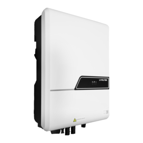
A
B
C
Figure 1. Appearance
Position
Designation
A
Battery SOC indicator: Indicates the SOC status of the connected
lithium battery.
B
Inverter LED indicator: Displays the current operating status of
the inverter
C
Nameplate Label: Clearly identify the product, including the SN,
technical data, certifications, etc.
Figure 2. Dimension

11
Figure 3. Terminals on the inverter
Position
Description
A
DC Switch (Optional)
B
PV Inputs(one or two pairs, depending on the model)
C
Grid output for connection to the utility grid
D
MULTI COM Port for CT/PA/EV connection
E
DRM Port
F
BMS Port
G
Battery Connectors
H
EPS Output for backup loads
I
Communication Port for Wi-Fi /4G (Optional) Stick
J
Additional Grounding terminal

12
3.3 System Diagram
DC
AC
Communication
Mobile APP Grid
Battery Internet
Billing
Meter
PV Array Hybrid
Inverter Router Loads Smart
Meter or CT

13
3.4 Work Modes
The hybrid inverter offers four operating modes (Self-use, Self-define, backup and off-
grid) that can be configured via LIVOLTEK APP for you to determine which mode will
be best for you.
Modes
Description
Self-Use (Default)
•The energy produced by the PV system will go for loads
consumption first, then charge battery, rest power
exports to grid, battery will charge or discharge
automatically based on the system condition.
•Suitable for areas with the low import rate and high
electricity price.
Self-Define
•Charge/discharge time can be set as customer need.
During the non-set time period, it will work in self-use
mode.
•Suitable for areas with time of use tariffs which means
prices vary between peak and valley.
Backup Mode
•When the grid is functional the battery is kept full
capacity and will only be allowed to discharge when grid
is unavailable
•Suitable for areas with unstable grid to prolong the
autonomy in the event of grid outage. Or reducing the
frequency charging & discharging of battery to extend
battery life.
Off-grid
•The critical loads will be powered byPV production and
Battery (Battery is necessary in this mode.)
•Suitable for non-grid areas, and the inverter will
automatic activation this mode in the event of grid
failure.

14
3.4.1 On-Grid Self-Use Mode
The purpose of this mode is to maximize the solar energy usage and lower the power
import from the grid.
When PV, grid, battery is available:
•If PV production ≥ Load consumption, PV production will go for loads consumption
first, the excess energy will be stored in the battery, and then exported to gird if needed
and configured that way *1.
•If PV production < Load consumption, the battery will discharge only for loads
consumption until reaches its power limit*2.
•If PV production + Battery < consumption, the system will import power from the grid
to power the loads, not for battery charge.
•The power switch between PV production, battery and grid is automatic and seamless.
When PV, grid is available (without battery):
•If PV production ≥ Load consumption, PV production will go for loads consumption
first, then the excess will export to the grid.
•If PV production < consumption, the system will import power from the grid to power
the loads, not for battery charge*3.
When PV, battery is available (Grid is disconnected):
•In the event of a grid failure or there is no mains, the hybrid inverter automatically
switches to Off-grid operation mode.
The off-gird mode ensures that the system forms a battery-backup grid that utilize power
from PV production and battery to supply power to critical loads.
•The switch time in the system is less than 20ms from one mode to another.
Notes:
*1: The inverter offers an export limitation function for you to decide whether you have
a grid limitation, and specify its value via LIVOLTEK APP. The export power should
not be more than the limit value set in commissioning
*2: The battery will stop to discharge when the value is lower than the discharge cut-off
SOC of lithium batteries or discharge cut-off voltage of lead-acid batteries, which is
available for setting. And the battery power supply can be restored when the battery is

15
charged to the “set value +10%” by solar.
*3: The battery will be charged only when PV production is sufficient.
3.4.2 On-Grid Self-Define Mode
On-Grid Self-Define Mode also called Time-of-use Mode. When operating in this mode,
the charging and discharging time can be set flexibly according to your wishes, and it
also allows to choose whether charge from the grid or not*1. This mode is ideal for those
who want to store the power into the battery when the electricity price is in the off-peak
rate and use the power in peak rate time or save the energy for blackout.
When PV, grid, battery is available:
•During charge time, solar energy and grid will charge battery*2 as first priority at the
same time, the excess solar energy will go for loads consumption and exported to gird if
needed and configured that way.
•During discharge time, PV production will go for loads consumption first, battery and
excess solar energy will export to the grid*3 at the same time.
•During the period of no charge or discharge, the inverter will automatically work in the
Self-Use mode.
When grid, battery is available (PV is disconnected):
•During charge time, grid will charge battery and supply power to the connected loads at
the same time.
•During discharge time, battery will discharge to EPS loads first, then the excess energy
will export to the grid.
Notes:
*1: Firmware update may be required to support this mode.
*2: You can choose whether to import from the grid to charge the battery via the
LIVOLTEK APP.
*3: You can choose whether to export to the grid from the battery via the LIVOLTEK
APP.
3.4.3 On-Grid Backup Mode
•When operating in this mode, solar energy and grid will fully charge battery as first

16
priority at the same time.
•The loads will be supplied by the surplus solar production supplemented, if necessary
by the public electricity grid. The battery will be used only when the grid failure.
NOTICE
•If set zero feed-in, the system will not export power to grid when work on the mode
of self-use, self-define or backup. But a small amount of energy will still inevitably
be fed into grid due to unpredictable PV energy change and load fluctuations.
3.4.4 Off-Grid Mode
When operating in this mode, Photovoltaic and battery constitute a pure off-grid system,
the critical loads (EPS Loads) will be powered by PV production and if the PV production
is insufficient, battery will discharge to power the loads at the same time. (Battery is
necessary in this mode.)
NOTICE
•When battery is discharged to the DischargeEndSOC@EPS value, the inverter will
stop working and wait for the grid to recover or until there is sufficient power from
PV panels to charge the battery.
•If grid failure is a common occurrence in your area, it is recommended to adjust the
DischargeEndSOC@Grid higher to ensure there is more battery power available.

17
4. Unpacking and Storage
The inverter is thoroughly tested and strictly inspected before delivery. Damage may still
occur during shipping. Please check the outer packing for damage and the inner contents
for any visible damage. Contact your distributor immediately in case of any damaged or
missing components.
4.1 Packing List
A
B
C
D
E
F
G
H
I
J
K
L
M
N
O
P

18
Position
QTY
Designation
A
1
Inverter
B
1
Inverter Bracket (Split Application)
C
1
EPS Plug for backup loads (critical Loads)
D
1
AC Plug for Grid
E
4
Positive & Negative PV Plugs (Two pairs)
F
1
Wi-Fi & Bluetooth integrated Stick
G
1
CT(Current Transformer) & CT cable
H
1
16pin COM connector for CT/Parallel/EV charger
I
2
Positive & Negative BAT Plugs (one pairs)
J
4
Expansion bolts for Wall-mounting Bracket(Split
Application)
K
1
Screws for Fixing Mounting Bracket
L
1
PE terminal
M
1
Water-proof RJ45 Connector for BMS
N
1
Water-proof RJ45 Connector for DRM port
O
1
Quality Certificate
P
2
Documents( User Manual & Quick Guide)
Notes: If anything is missing, please contact your local distributor.

19
4.2 Identify the Inverter
4.2.1 Nameplate
After moving the hybrid inverter from package, identify it by reading its nameplate
labeled on the side of the inverter. The nameplate contains important product
information: the model information, technical specifications and compliance symbols.
Take Hyper 5000 as an example.
Logo, product model,
Compliance symbols
Key technical data
Certification of inverter
SN (serial number)
Company name, website
and country of origin
Notes: The image shown here is for reference only. The actual product received may differ.

20
4.2.2 Compliance and Safety Symbols
Symbol
Explanation
CE marking
The product complies with the requirements of the applicable EU
directives.
UKCA marking
The inverter complies with the requirements of the applicable UKCA
guidelines.
UKNI marking
The inverter complies with the requirements of the applicable UKNI
guidelines.
Caution! Beware of a danger zone!
Failure to observe any warnings contained in this manual may result
in injury.
Danger! Beware of hot surface!
The inverter can become hot during operation.
Danger! Beware of high voltage and electric shock!
Beware of electrical voltage, the product operates at high voltages.
Observe the documentation.
Observe all documentation supplied with the product.
WEEE designation.
Do not dispose of the product together with the household waste but in
accordance with the disposal regulations for electronic waste
applicable at the installation site.
Danger to life due to high voltage and electric shock!
There are residual voltages in the inverter after powering off, you
should wait at least 5mins after disconnecting the inverter from the
utility grid and from the PV panel before touching any inner live parts.
This manual suits for next models
3
Table of contents
Other LIVOLTEK Inverter manuals
Popular Inverter manuals by other brands

Generac Power Systems
Generac Power Systems PWRcell X7600 Series owner's manual

Carrier TRANSICOLD
Carrier TRANSICOLD PowerLINE Series Operation and service manual

SOLINTEG
SOLINTEG INTEG M MHT Series Quick installation guide

INFOSEC
INFOSEC C3 MPPT user guide

FoxESS
FoxESS E Series user manual

MULTIQUIP
MULTIQUIP TLG8SSK4F Operation and parts manual