LIVOLTEK GT3-17K-D User manual

Ver 00.
GT3 17K-30K

Contents
Forward
Application Model
Intended Audience
Symbol Conventions
1 Safety Precautions
1 1 Personnel Safety.
1 2 The PV Inverter Protection.
1 3 Installation Safety.
1 4 Electrical Connections.
1 5 Operating and Commissioning.
1 6 Maintenance.
1 7 Additional Information.
2 Overview of the Inverter
2 1 Functional Models.
2 2 Network Application.
2 3 Outline and Dimensions.
2 4 Working Modes.
2 1 1 Function. .
2 1 2 Model Description. .
2 3 1 Dimensions. .
2 3 2 Outline. .
2 2 1 Grid tied PV Power Systems. . -
4 1 Checking the Outer Packing.
4 2 Moving the Inverter.
4 3 Identify the PV Inverter.
4 4 Installation Requirements.
4 3 1 Nameplate. .
4 3 2 Compliance and Safety Symbols. .
3 Storage
4 Installation
01
01
01
02
03
03
03
03
04
04
04
05
06
06
06
06
06
06
07
07
08
09
11
12
12
12
13
13
13
10
11
4 4 1 Determining the Installation Position. .

5 Electrical Connections
5 1 Connecting Protection Ground PGND Cables. ( )
5 2 Connecting AC Output Cables.
5 3 Connecting the PV Strings.
5 4 Connecting Communication Cables.
5 5 Installation Verification.
5 1 1 Preparation. .
5 1 2 Wiring Procedures. .
5.4.1 Communication Mode Description
5 3 1 Preparation. .
5 2 1 Preparation. .
5 2 2 Procedure of Connecting AC Cables. .
5 3 2 Procedure of connecting the PV Strings. .
6 System Operation
6 1 Powering ON the Inverter.
6 2 Powering OFF the Inverter.
7 User Interface
8 Maintenance
9 Disposal of the Inverter
10 Technical Specifications
8 1 Routine Maintenance.
8 2 The Inverter Troubleshooting.
8 3 Removing the Inverter.
4 5 Support mounting the Inverter. -
4 6 Installation Self check. -
19
19
19
20
21
21
22
26
24
25
28
28
29
30
30
30
31
34
39
40
34
35
37
17
17
18
4 4 2 Installation Mode Requirements. .

1
GT3-17K/20K/22K-D
GT3-25K/28K/30K-D
Forward
Dear User,
Thank you so much for your choosing GT3 17K-30K, the latest generation of grid-tied PV
Strings inverter (hereinafter referred to as the inverter) designed and developed by our
company.
This user manual introduces the inverter in terms of its installation, electrical connections,
operation, commissioning, maintenance, and troubleshooting. Please read through the manual
carefully before installing and using the inverter, and keep the manual well for future reference.
Application Model
This user manual is intended for photovoltaic (PV) inverter operating personnel and qualified
electrical technicians.
Intended Audience
This user manual is subject to change specific please in kind prevail without prior notice( ) .
Notes:
Grid-tied PV string inverter

2
Indicates an imminently hazardous situation which if not correctly,
followed will result in serious injury or death, .
Indicates a potentially hazardous situation which if not correctly,
followed could result in serious injury or death, .
Indicates a potentially hazardous situation which if not correctly,
followed could result in moderate or minor injury, .
Indicates a potentially hazardous situation which if not correctly,
followed could result in equipment failure to run or property damage, , .
Calls attention to important information best practices and tips, :
supplement additional safety instructions for your better use of the
PV inverter to reduce the waste of your resource.
Refer to documentation (Remind operators to refer to the
documentation shipped with the inverter).
Symbol Conventions
Safety symbols used in this manual which highlight potential safety risks and important safety,
information are listed as follows, :
Symbol Description
WARNING
CAUTION
DANGER
NOTICE
NOTE
Refer

3
1 Safety Precautions
Before beginning your journey please read these safety precautions in User Manual carefully, .
a. The PV inverter must be installed electronically connected operated and maintained through, ,
specially trained technician;
b The qualified technician must be familiar with the safety regulations of electrical system. ,
working process of PV power generation system, and standards of local power grid;
c. The technician must read through this User Manual carefully and master it before any operation.
1 1 Personnel Safety.
a Do not tamper with any warning signs on the inverter enclosure because these signs contain.
important information about safe operation.
b Do not remove or damage the nameplate on the inverter’s enclosure because it contains.
important product information.
c Do not remove the anti dismantle label on the inverter’s enclosure because it is the basis for. -
product warranty.
1 2 The PV Inverter Protection.
a Ensure there is no electronical connections around ports of the PV inverter before installing. ;
. .b Adequate ventilation must be provided for inverter installation location Mount the inverter in
vertical direction, and ensure that no object is put on the heat sink affecting the cooling. (For
details, refer to Chapter 4 Installation)
1 3 Installation Safety.
As soon as receiving the PV inverter please check if it is damaged,
during its transportation If yes please contact your dealer immediately. , .
Please read the User Manual carefully before installing the PV inverter;
warranty or liability will be void from o if damage is causedur company
by installation faults.
NOTICE
NOTICE

4
a Input terminals of the PV inverter apply only to input terminals of PV String do not connect. ;
any other DC source to the input terminals.
b Before connecting PV modules ensure that is its voltage is within the safe range when. , ;
exposed to any sunlight, PV modules can generate high voltage.
c All electrical connections must meet the electrical standards of the country or region. .
. , ,d Cables used in electrical connections must be well fixed good insulation and with
appropriate specification.
1 4 Electrical Connections.
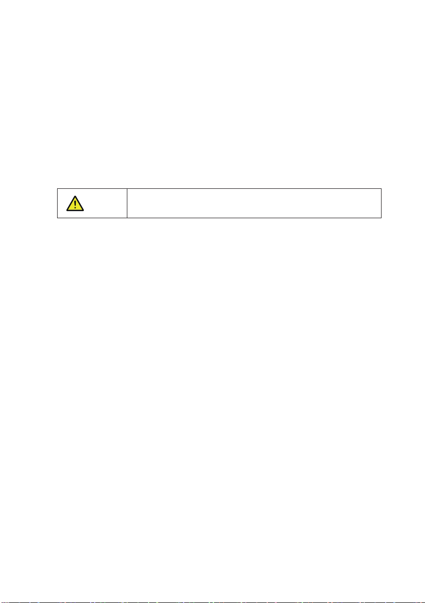
A Before getting the permission of electrical power sector in the country/region the grid-tied. ,
PV inverter cannot start generate power.
b Follow the procedures of commissioning described in the user manual when commissioning.
the PV inverter.
c Do not touch any other parts surface except the DC switch when the PV inverter is operating. ' ;
its partial parts will be extremely hot and can cause burns.
1 5 Operating and Commissioning.
1 6 Maintenance.
Before installing the inverter check all electrical ports to ensure no,
damage and no short circuit Otherwise personal casualty and or fire. /
will occur.
While the inverter operating high voltage can lead to an electrical,
shock hazard and even cause personal casualties Therefore, . ,
operate the PV inverter strictly according to the safety precautions in
the user manual.
Power OFF all electrical terminals before the inverter maintenance;
strictly comply with the safety precautions in this document when
operating the inverter.
DANGER
DANGER
DANGER

5
a For personal safety maintenance personnel must wear appropriate personal protective. ,
equipment (like insulation gloves and protective shoes) for the inverter maintenance.
b Place temporary warning signs or erect fences to prevent unauthorized access to the.
maintenance site.
c Follow the procedures of maintenance stipulated in the manual strictly. .
. ;d Check the relevant safety and performance of the inverter rectify any faults that may
compromise the inverter security performance before restarting the inverter.
1 7 Additional Information.
To avoid any other unforeseeable risk, contact your dealer immediately
if there is any issue found during operation.
NOTICE

6
2 Overview of the Inverter
This chapter introduces the inverter and describes its functional model network application, ,
, , .appearance dimensions and working process etc
2 1 1 Function. .
This series is a three-phase grid-tied PV string inverter transformer less that converts the DC( )
power generated by PV strings into AC power and feeds the power into power grid.
21 2 Model Description. .
Figure 2 1 shows a model number of the inverter using 17K as an example. , .
Figure 2 1 Model number descriptions.
2 1 Functional Models.
22 1 Grid-tied PV Power Systems. .
The series apply to grid-tied PV power systems for industrial/commercial rooftops, fishing/farmers
light complementary power generation systems, and large ground-based power stations, as
shown in Figures 2.2.
2 2 Network Application.
The inverter is transformerless Add an isolation transformer before.
grounding the positive negative terminal of PV modules like Thin/ (
Film module for operation) .
Do not connect PV modules in parallel to several PV inverters for
operation.
WARNING
WARNING
GT3-3K-DD:double MPPT
Power class code
3:three phase

7
2 3 Outline and Dimensions.
Figure 2 2 a low-voltage grid-tied PV power system.
PV strings inverter AC Distribution Unit low-voltage power grid
Figure 2 3 Power grids supported by these series inverters.
Inverter
TN S-TN C-TN C S- - TT
Inverter Inverter Inverter
Figures 2 4 The dimensions of the PV inverter (unit: mm).
2 3 1 Dimensions. .
Figures 2.4 shows the dimensions of PV inverter as follows:
These series support the power grid modes TN-S, TN-C, TN-C-S, and TT, as shown in Figure 2.3.
555
469.5
270.5

8
Figure 2 6 The rear view of PV inverter.
Figure 2 7 The bottom view of PV inverter.
Install the backboard
1.PV Strings connectors
2.DC Switch
3.Communications interface
4.R 485S
5.AC output connectors
6.Fan(25K/28K/30K)
7.Vent valve
8 External Protection Ground interface.
2 3 2 Outline. .
Figures 2 5 to 2 7 show the outline of the inverters as follows. . :
Figure 2 5 The front view and amplification effect of LED indicator area.
1 PV Indicator.
2 Grid Indicator.
3COM Indicator.
4 Warning Indicator.
8

9
Table 2 1 Working modes description.
2 4 Working Modes.
Three working modes of the inverter are shown as follows standby operating and shutdown: , , .
. .Table 2 1 shows the conditions for the inverter to switch between working modes
The PV inverter enters the standby mode when
the input voltage of PV Strings can enable auxiliary power supply to run> ,
but cannot meet the inverter operation requirements.
the input voltage of PV Strings can meet the inverter to start requirements> - ,
.but cannot meet its minimum power requirements
When the PV inverter is grid tied and generates electricity it- ,
tracks the maximum power point to maximize the PV String output> .
>converts DC power from PV strings into AC power and feeds the power
to the power grid.
The PV inverter will enter to the shutdown mode if detecting a fault or a
shutdown command.
Modes
Standby
Operating
Description
The PV inverter switches from standby or operating mode to shutdown
mode if detecting a fault or a shutdown command.
The inverter switches from shutdown mode to standby mode if receiving
a Startup command or detecting that a fault is rectified.
Shutdown

10
3 Storage
This chapter describes the storage requirements for the inverter.
The following storage instructions apply if the PV inverter will not be deployed immediately:
> .Do not unpack the inverter (put desiccant in the original box if the PV inverter is unpacked)
> ℃ ℃Store the PV inverter at a temperature range of -40 to +70 and with the relative humidity
of 0% to 100% (no condensing).
The PV inverter should be stored in a clean and dry place and be protected from dust and>
water vapor corrosion.
A maximum of four layers of inverters can be stacked.>
> , , , .Do not position the inverter at a front tilt excessive back tilt or side tilt or upside down
> .Conduct periodic inspection during storage Replace the packing materials immediately if any
rodent bites are found.
Ensure that qualified personnel inspect and test the inverter before use if it has been stored>
for a long time.

11
4Installation
4 1 Checking the Outer Packing.
a When receiving the inverter check that the packing materials are intact. , .
. , , ,b After unpacking check that the deliverables are complete intact and consistent with your
order list.
c Examine the PV inverter and its fittings for damage such as scraps and cracks. .
Do not install the inverter on flammable building materials or in an
area that stores flammable or explosive materials.
Do not install the inverter in a place where personnel are likely to
come into contact with its enclosure and heat sinks to avoid electrical
shock/burn.
Figure 4 1 The deliverables: The inverter and its fittings.
CAUTION
DANGER
AC output connector
The inverter
Items Deliverables
File package
Rear panel
A
F
G
E
D
C
B
Bolt group (including screw, nut)*3
(reserved for tighteningthe support and rear panel)
M6 screw
DC terminal connector group
The deliverables in the fittings of inverter
G

12
Figure 4 2 Moving the inverter.
The inverter is relatively heavy! To prevent device damage and personal
injury it need two people to move the inverter and handle with care, .
>Do not place the PV inverter with its wiring terminals contacting the
floor because the power ports and signal ports at the bottom of the
device are not designed to support the weight of the inverter.
> ,When placing the inverter on the floor horizontally put foam or
paper under to protect its enclosure.
4 3 1 Nameplate. .
After moving the PV inverter from packing box, identify it by reading its nameplate labeled on the
side of the inverter. The nameplate contains important product information: the model information,
communication/technical specifications, and compliance symbols shown in inverter.
4 3 Identify the PV Inverter.
CAUTION
CAUTION
If any damage mentioned above is found contact the dealer,
immediately.
42 Moving the Inverter.
NOTICE
After checking the outer packing, move the PV inverter to the designated installation position
horizontally, as shown in Figure 4.2.

13
4 3 2 Compliance and Safety Symbols. .
Electrical shock!
There are residual voltages in the PV inverter It needs 10 minutes.
to finish discharge.
10min
The PV inverter must not be touched when in operation Its.
enclosure and heat sinks are extremely hot.
Electrical shock! This part is charged Only qualified and / or trained.
electrical technicians are allowed to perform operations on the inverter.
If the inverter service life has expired dispose it in accordance with,
local rules for disposal of electrical equipment waste Do not dispose.
the PV inverter with household garbage.
Safety symbol Description
According to installation position, one kinds of physical installation are described below in detail:
Support-mounting.
Basic Requirements
a The inverter is protected to IP65 and can be installed indoors or outdoors. .
b The installation method and position must be appropriate for the weight and dimensions of.
the inverter.
c Do not install the inverter in a place where personnel are likely to come into contact with its.
enclosure and heat sinks because these parts are extremely hot during operation.
d Do not install the inverter in an area that stores flammable or explosive materials. .
a The ambient temperature must be below 50 which ensures the inverter’s optimal. ℃
operation and extends its service life.
Installation Environment Requirements
4 4 1 Determining the Installation Position. .
4 4 Installation Requirements.
The PV inverter is compliant with TUV.

14
b The inverter must be installed in a well ventilated environment to ensure good heat dissipation. .
cThe inverter must be free from direct exposure to sunlight rain and snow to extend its service. , ,
life. It is recommended that the inverter be installed in a sheltered place. If no shelter is
available, build an awning, as shown in Figure 4.3.
Figure 4 3 Installation environment with awning unit mm. ( : )
Carrier Requirements
Installation Space Requirements
a It is recommended that the inverter be installed at eye level to facilitate operation and.
maintenance.
b Reserve enough clearance around the inverter to ensure sufficient space for installation.
and heat dissipation, as shown in Figure 4.4.
a The carrier where the inverter is installed must be fire-proof Do not install the inverter on. .
flammable building materials.
b The wall must be solid enough to bear the weight of the inverter. .
c Do not install the inverter on a wall made of gypsum boards or similar materials with weak.
sound insulation to avoid noise disturbance in a residential area.
the front view
Awning
the lateral view
≥500
≥1000

15
Figure 4 4 Installation Space Requirements unit mm. ( : )
c When installing multiple inverters, install them along the same line (as shown in Figure 4.5).
if sufficient space is available, and install them in triangle mode (as shown in Figure 4.6) or
in stacked mode (as shown in Figure 4.7) if no sufficient space is available. The installation
modes ensure sufficient space for installation and heat dissipation.
Figure 4 5 Installation along the same line unit mm. ( : )
>1000
200 200
>500
>600
>200 >200
Distance from air duct to obstacle
Do not place obstacles in the dotted frame
to avoid blocking the air duct
>600

1000
200
100
300
Figure 4 6 Installation in triangle mode (unit: mm).
Figure 4 7 Installation in stacked mode (unit: mm).
The clearance between multiple inverters must be increased to
ensure proper heat dissipation when they are installed in a hot area.
NOTICE
16

17
4 4 2 Installation Mode Requirements. .
Install the inverter upright or at a maximum back tilt of 15 degrees to facilitate heat dissipation.
, . . .Below are some correct / wrong installation modes as shown in Figure 4 8&4 9
Figure 4 8 The correct installation mode.
The correct installation mode
upright back tilt
Figure 4 9 The wrong installation modes.
The wrong installation will lead to failure of the inverter operation.
NOTICE
The wrong installation mode
Horizontally Upside down-
Step 1 Support-mounting the inverter is recommended. Tighten the support and rear panel using
M12 bolt and the required torque is 42N.m as shown in Figure 4 10., .
4 5 Support-mounting the Inverter.
Figure 4 10 Securing a rear panel.
Φ14
This manual suits for next models
5
Table of contents
Other LIVOLTEK Inverter manuals