manuals.online logo
Brands
  1. Home
  2. •
  3. Brands
  4. •
  5. LK Armatur
  6. •
  7. Temperature Controllers
  8. •
  9. LK Armatur SmartComfort LK 110 User manual

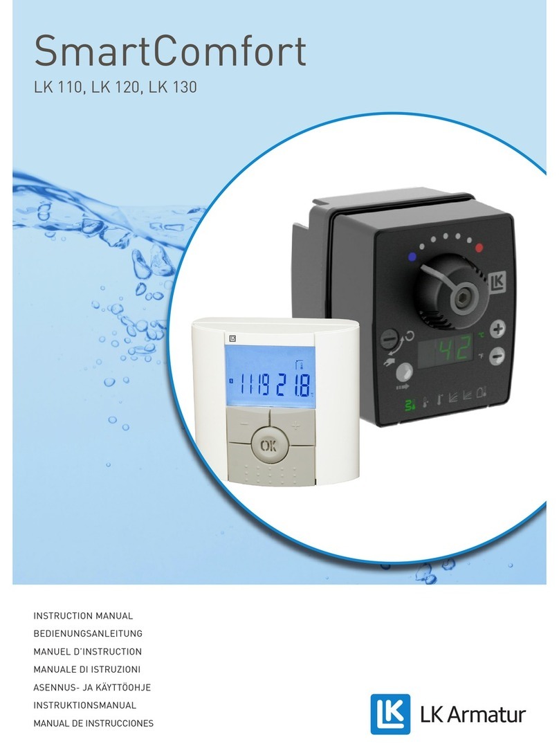
LK Armatur SmartComfort LK 110 User manual

NSTRUCT ON MANUAL
BED ENUNGSANLE TUNG
MANUEL D’ NSTRUCT ON
MANUALE D STRUZ ON
ASENNUS- JA KÄYTTÖOHJE
NSTRUKT ONSMANUAL
MANUAL DE NSTRUCC ONES
LK 110, LK 120, LK 130
SmartComfort
4
GB ENGL SH
Technical Data
Protection class..................................................................... SELV (EN 60730-1) (double insulated)
Surrounding temperature, actuator and room controller 0 to +50°C, +32°F to +122°F
Air humidity....................................................................................<90% Rh, without condensation
Enclosure class, actuator................................................................. P 40 (according to EN 60529)
Enclosure class, room controller.................................................... P 20 (according to EN 60529)
Enclosure class, outdoor sensor..................................................... P 66 (according to EN 60529)
Enclosure class, AC adapter............................................................ P 20 (according to EN 60529)
Primary voltage, AC adapter......................................................................100 - 240 VAC, 50/60 Hz
Connector, AC adapter...........................................................Europlug CEE 7-6 or USA: NEMA 1-15
or UK: BS1363
Angle of rotation / Actuator direction...................................90°/clockwise and counterclockwise
Actuator torque..........................................................................................................................5 Nm
Room temperature, setting range (LK 120 & LK 130).................+5°C to +37°C, +41°F to +99°F
Operating modes (LK 120 & LK 130)....................Comfort/Reduced/Automatic/Holiday/ Timer
Clock (LK 120 & LK 130)...............................12 hrs. AM/PM and 24 hrs. Running reserve 24 hrs.
Manual operation.................................................................................................Yes, when needed
ndoor temperature range (LK 120 & LK 130)................................0°C to +50°C, 32°F to +122°F
Outdoor temperature range (LK 110 & LK 130)........................-50°C to +50°C, -58°F to +122°F
Water supply temperature setting...................................................+5°C to 99°C, +41°F to 210°F
Regulating curve, setting (LK 110 & LK 130)......................................................................1.0 - 9.9
Parallel shift of regulating curve (LK 110 & LK 130).............................................+-10°C, +-18°F
Min. flow temperature (LK 110, LK 120 & LK 130).......................+5°C to +40°C, +41°F to 104°F
Max. flow temperature (LK 110, LK 120 & LK 130)....................+20°C to +99°C, +68°F to 210°F
Dimensions, actuator............................................................Length x width x height 93 x 80 x 75 mm
Dimensions, room controller.................................................................Width x height x thickness
Dimensions, AC Adapter........................................................Length x width x height 74x 30 x 43 mm
The class of the temperature control...........................................LK 110 SmartComfort: Class
LK 120 SmartComfort: Class V
LK 130 SmartComfort: Class V
The contribution of the temperature control to seasonal
space heating energy efficiency.........................................................LK 110 SmartComfort: 2,0%
LK 120 SmartComfort: 3,0%
LK 130 SmartComfort: 4,0%
nstallation
nstalling the Actuator:
1. Rotate the axle on the mixing valve A counterclockwise and re-
move the knob without changing the position of the axle.
2. Screw the fixation bolt B in a suitable hole on the mixing valve
A. Remove any existing bolt. Push the adapter C on the mixing
valve axle so that the axle bottoms in the hole. The supplied
adapter C suits most valve axles. Other versions of this adapter
are available as accessories. Please contact LK Armatur AB for
more information.
3. Fit the actuator D to the adapter C. The bolt B should fit in the
intended hole on the actuator.
4. Fit the knob E so that the indicator points to the counterclock-
wise end position. Tighten the knob with the washer and the
bolt F.
5. Use a screwdriver to turn the disengaging button G to the posi-
tion with hand symbol . Turn the valve with the knob E
Delivery Check
Check that the delivery, depending
on model, includes the components
listed below.
Actuator
Mounting kit (Fixation
bolt, fixing screw, lock-
washer, adapter)
Knob with indicator
Room controller
with 15 m cable or
with antenna
Outdoor sensor
with 15 m cable
Water supply sensor
with 1 m cable
AC adapter 100-240
VAC, 50/60 Hz with 1.8
m cable
Cable ties
Model LK
110 120 130
$ % & '
*
(
)
A B C D G E F
Functional Description
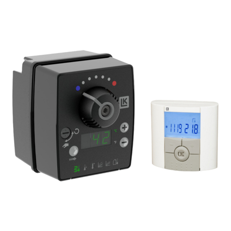
LK 110, LK 120 and LK 130 SmartComfort are electronic tempe-
rature controllers for hydronic radiator and underfloor heating
applications. All models are equipped with frost protection and
minimum/maximum limitation of the supply temperature.
LK 110 and LK 130 are equipped with an outdoor sensor. The supply
temperature is adjusted according to the outdoor temperature.
LK 120 and LK 130 are provided with a room controller. The
controller can be set to the desired room temperature. To
save energy, there are programmes that have scheduled
temperature changes.
LK 130 is equipped with an outdoor sensor, a supply sensor and
a room controller to optimize the control of the heating system.
from one end position to the other. t is important that the motor
can be turned the whole turning angle (90°).
6. Turn the decoupling screw G back to the Automatik position .
5
GB ENGL SH
Warning! Risk of burns!
Avoid touching the hot supply line pipe when
clamping the supply sensor.
Room Controller A
For models LK 120 and LK 130. See the separate instruction ma-
nual for the room controller.
Outdoor Sensor B
For models LK 110 and LK 130. Fit the outdoor sensor on the
north exterior wall of the building, so that it is not exposed to solar
radiation. The position should be approximately 3 meters above
the ground. The outdoor sensor must not be positioned above
windows or doors or under eaves, near exhaust grilles or other
openings which can affect the sensor temperature.
Connect the sensor cable to the connector marked on the actua-
tor.
Water Supply Sensor C
Use the supplied cable ties to clamp the supply sensor on an
uninsulated part of the supply line approximately 1 m after the
mixing valve. f necessary, thermal conductivity paste can be
applied. The pipe must then must be insulated to obtain the
best temperature measurement.
Connect the sensor cable to the connector marked on the actua-
t
or.
Adapter D
Plug the adapter into the slot marked on the actuator.
Warning! The adapter must never be exposed to water.
Pump Control E (Option)
For further energy saving a pump control is available as an op-
tional accessory. The pump will be stopped 30 minutes after
the actuator has fully closed the mixing valve. The pump will
restart as soon as the actuator opens the mixing valve.
After 48 hours downtime the pump control will set the pump run-
ning for 1 minute with the mixing valve in a closed position.
See separate manual for installation of the pump control.
System Schedule
Valve Exercise
An anti-block function will be activated if the mixing valve has
been closed for more than 24 hours. The valve will be turned
from one end position to the other to prevent it from getting
blocked. f the flow temperature rises rapidly, the mixing valve will
return to closed position. The anti-block function can be deactiva-
ted by simultaneously pressing the function selector and the
minus button for about 5 sec. The text ”no” is shown in the dis-
play. To activate the function, press the function selector and
the plus button simultaneously for about 5 sec. “YES” will now
appear in the display.
Function and Fault ndication
The coloured indicators on the actuator indicate functions and
faults.
• Blue and red lights flash alternately wile the automatic se-
lection of direction is in progress.
• Blinking blue lights in both indicators during automatic se-
lection of direction indicate that the actuator does not sense
heat in the system.
• A white light will flash if a fault has occurred. A fault code
is shown in the display.
Fault Codes:
E11 Water supply sensor
E12 Outdoor sensor ( n LK 120 RTW communication error)
E14 Room controller, communication error
E50 Room controller, temperature sensor
Troubleshooting
When a temperature setting in the system has been changed ,
it takes time, from a couple of hours up to 24 hours, before the
room temperature corresponds to the new setting. The time is
depending on the operation of the heating system, the dimen-
sioning, the isolation degree of the building etc.
f the heating system, in view of this fact, still does not work satis-
factorily, check that:
1. the heating boiler or the storage tank has the correct tempe-
rature.
2. the circulation pump is running.
3. the radiator- and shut-off valves are open.
4. the power is supplied and the fuses in the house are intact.
5. the mixing valve can be turned easily.
6. the actuator has been correctly installed on the mixing valve
axle.
7. there is no air in the system.
8. the control system is correctly installed.
9. the curve setting is correct (page 6).
10. the parallel shift of the curve is correct (page6).
11. the disengaging button is in the automatic position .
12. the installation of the heating system has been carried out cor-
rectly and can be operated manually.
A B
C
E
D
6
GB ENGL SH
6
Temperature Display
The temperature can be displayed in °C or °F. The factory setting
is °C. To change temperature unit, press plus and minus buttons
simultaneously for at least 3 sec.
Manual Operation
The actuator can be disengaged to allow manual operation of
the mixing valve. Turn the disengaging button 90° clockwise to
the hand position symbol . The symbol will now start flashing.
Automatic Selection of Direction
Adaption to mixing valves with different opening directions is done
by an actuator test to determine if the valve opens clockwise or coun-
terclockwise. The test takes some minutes and occurs at first startup.
The actuator selects and saves the opening direction. Automatic se-
lection of only works when there is heat in the system. f the automa-
tion cannot decide direction, a manual choice should be made.
Manual Selection of Direction
Check the opening direction of the mixing valve. Adapt the ope-
ning direction of the actuator in the following way:
Clockwise direction: Push the plus button and then power
up the actuator. The display counts down 3-2-1. Let go of the plus
button. The direction is indicated by a red light to the right on the
actuator. The automation selects clockwise direction and the indi-
cation switches to fixed light.
Counter-clockwise direction: Push the minus button and
then power up the actuator. The display counts down 3-2-1. Let
go of the minus button. The direction is indicated by a red light to
the left on the actuator. The automation selects counter-clock-
wise direction and the indication switches to fixed light.
Min. Temperature (Antifreeze)
The working range of the actuator can be limited to prevent the tem-
perature from falling below a set value (provided that there is heat
in the system). Step to the symbol for min. temperature by using
the function selector. ncrease or decrease the value by using the
plus or minus button. The min-value cannot be set above the max-
value. The max-value will automatically increase as soon as the
min-value reaches the max-value. The max-symbol will flash to
indicate that the temperature setting has been changed.
Note! SmartComfort has a built-in antifreeze function, which
will make the mixing valve stay in approximately 30° position
should the supply temperature sensor be defective. f this cau-
ses risk of damage to the heating system an overheating pro-
tection device should be installed.
ndication
Above the knob on the actuator, there are two
indicators for hot (red) and cold (blue). At normal
operation, both indicators shine. f the angle
of rotation is changed, the indicator blinks
in the turning direction The blinking shifts
to fixed light shortly after the motion has
stopped.
indicators
ACTUATOR, FUNCT ONS AND SETT NGS Max. Temperature
The working range of the actuator can be limted to prevent the tem-
perature from rising above a set value. Step to the symbol for max.
temperature by using the function selector. ncrease or decrease
the value by using the plus or minus button. The max-value cannot
be set below the min -value. The min-value automatically decreases
as soon as the max-value reaches the min-value. The min-symbol
will flash to indicate that the temperature setting has been changed.
This temperature limitation can be used e.g. to protect sensitive
building structures such as wooden floors with underfloor heating.
Curve Control
For model LK 110 and LK 130. This operation converts the measu-
red outdoor temperature to an internal setpoint with the help of a
curve control. The curve must be adjusted and parallel shifted to
match different buildings and the operation of the heating system.
n model LK 130, the setpoint is also affected by the difference bet-
ween the indoor temperature (measured by the room controller) and
the setpoint in the room controller (the desired room temperature).
Curve Setting
For model LK 110 and LK 130. The curve can be adjusted from
1.0 to 9.9. Step to the symbol for curve by using the function
selector. ncrease or decrease the slope of the curve with the
plus or minus button.
Recommended basic setting:
Radiator system Curve setting 3.0
Floor heating system in wooden joists Curve setting 1.5
Floor heating system in concrete Curve setting 1.0
Parallel shift of the Curve
For model LK 110 and LK 130. With the parallel shift of the cur-
ve the flow line temperature can be changed +-10°C/+-18°F. To
change the room temperature by 1°C, the supply temperature
should be changed 2 - 4°C. Step to the symbol for parallelshift
by using the function selector. Change the position of the
curve with the plus or minus button.
Reset to Factory Settings
Press the plus and minus buttons simultaneously during power-
up. The display counts 0-9-8-7-6-5-4-3-2-1-0. Let go of the buttons.
(C°)
(C°)





7
HPSHUDWXU
H

     






6XSSO\
7
2XWGRRU7HPSHUDWXUH



Other manuals for SmartComfort LK 110

2

This manual suits for next models

2

Other LK Armatur Temperature Controllers manuals

LK Armatur SmartComfort LK 120 User manual

LK Armatur

LK Armatur SmartComfort LK 120 User manual

LK Armatur SmartComfort LK 120 User manual

LK Armatur

LK Armatur SmartComfort LK 120 User manual

LK Armatur SmartComfort LK 120 User manual

LK Armatur

LK Armatur SmartComfort LK 120 User manual

LK Armatur SmartBio LK 160 User manual

LK Armatur

LK Armatur SmartBio LK 160 User manual

LK Armatur SmartComfort LK 110 User manual

LK Armatur

LK Armatur SmartComfort LK 110 User manual

Popular Temperature Controllers manuals by other brands

WIKA CS4S operating instructions

WIKA

WIKA CS4S operating instructions

Shinko ACS-13A Communication instruction manual

Shinko

Shinko ACS-13A Communication instruction manual

Danfoss ECL Comfort 110 operating guide

Danfoss

Danfoss ECL Comfort 110 operating guide

Auber Instruments SYL-1512A instruction manual

Auber Instruments

Auber Instruments SYL-1512A instruction manual

Kerda AL8010F user manual

Kerda

Kerda AL8010F user manual

Uponor Smatrix Move quick guide

Uponor

Uponor Smatrix Move quick guide

Lowrance EP-80R Temp Installation and configuration instructions

Lowrance

Lowrance EP-80R Temp Installation and configuration instructions

Tempcube TC-3200 Lite instruction manual

Tempcube

Tempcube TC-3200 Lite instruction manual

THERM PRO TX7B instruction manual

THERM PRO

THERM PRO TX7B instruction manual

Emerson TS1-G Operating	 instruction

Emerson

Emerson TS1-G Operating instruction

Elvaco CMa11L quick start guide

Elvaco

Elvaco CMa11L quick start guide

Mitsubishi Electric PAC-USWHS003-TH-1 Installation instructions manual

Mitsubishi Electric

Mitsubishi Electric PAC-USWHS003-TH-1 Installation instructions manual

Calex PyroSigma Series Operator's guide

Calex

Calex PyroSigma Series Operator's guide

PMA KS 50-1 quick start guide

PMA

PMA KS 50-1 quick start guide

Tekmar 078 Installation and operaion manual

Tekmar

Tekmar 078 Installation and operaion manual

Auber Instruments TH220 instruction manual

Auber Instruments

Auber Instruments TH220 instruction manual

Stafford Instruments ST312 User handbook

Stafford Instruments

Stafford Instruments ST312 User handbook

Honeywell ASC02-01WM Installation and operating instructions

Honeywell

Honeywell ASC02-01WM Installation and operating instructions

manuals.online logo
manuals.online logoBrands
  • About & Mission
  • Contact us
  • Privacy Policy
  • Terms and Conditions

Copyright 2025 Manuals.Online. All Rights Reserved.