manuals.online logo
Brands
  1. Home
  2. •
  3. Brands
  4. •
  5. LLURIA
  6. •
  7. Media Converter
  8. •
  9. LLURIA DMR-KNX-3 User manual

LLURIA DMR-KNX-3 User manual

Lluria se reserva el derecho de modificar las especificaciones.
Lluria reserves the right to modify specications.
1/4
v.2019.01
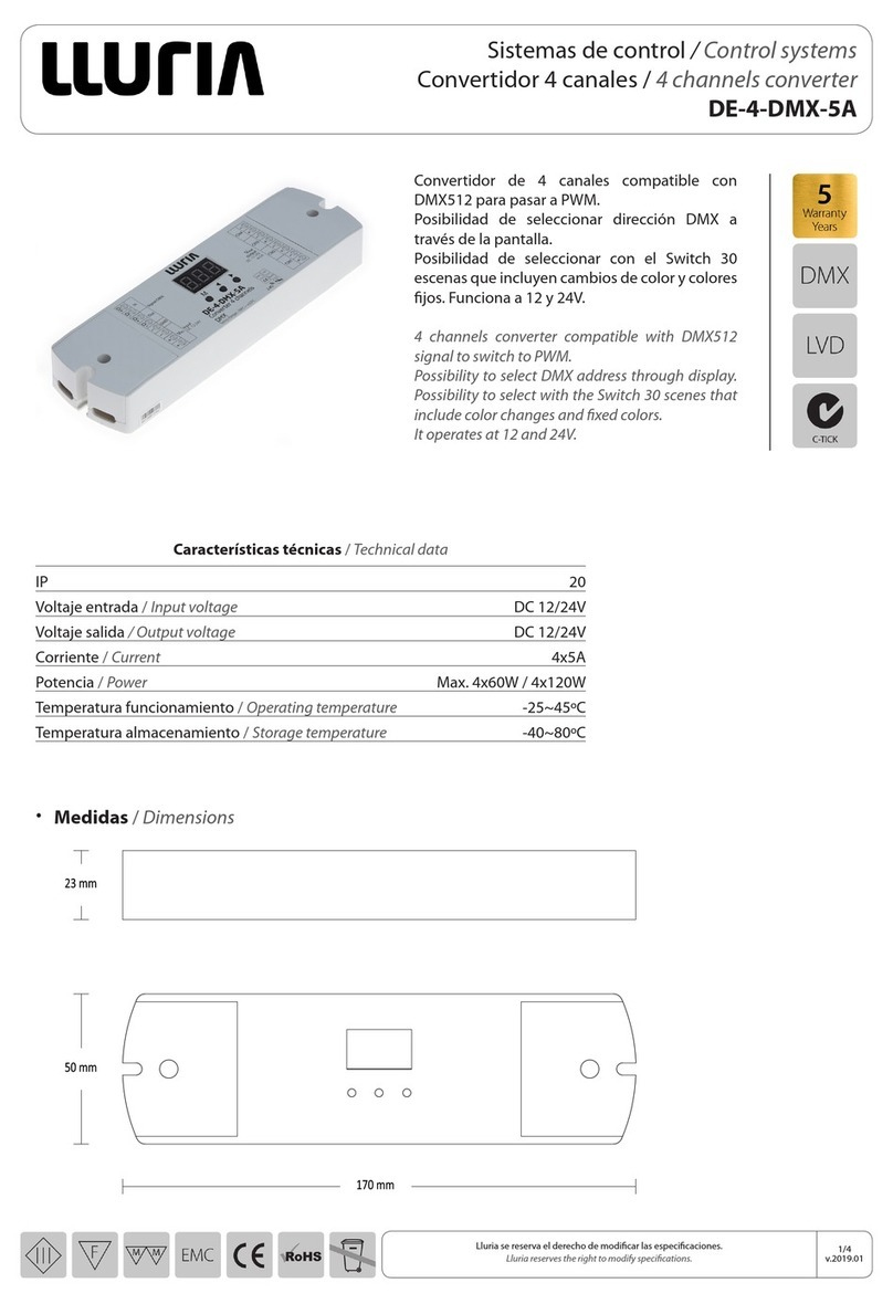
Sistemas de control / Control systems
Convertidor 3 canales / Converter 3 channels
DMR-KNX-3
Convertidor de 3 canales.
Convertidor de señal KNX a PWM. Permite
controlar una zona RGB o 3 zonas monocolor.
Dispone de función autotest para comprobar el
funcionamiento de los canales.
Funciona a 12 y 24V.
3 channels converter.
KNX signal converter to PWM. It allows controlling
a RGB zone or 3 single-color zone.
It has a self-test function to check the operation of
the channels.
It operates at 12 ans 24V.
Medidas /Dimensions
•
OUTPUT:
R - C1 <1>
G - C2 <2>
B - C3 <3>
NULL
LED
TEST
LED
PROG.
Características técnicas /Technical data
IP 20
Voltaje entrada / Input voltage DC 12/24V
Voltaje salida / Output voltage DC 12/24V
Temperatura funcionamiento / Operating temperature 0~45ºC
Temperatura almacenamiento / Storage temperature -40~80ºC
Corriente / Current 3x2.5A
Potencia / Power Max. 3x30W / 3x60W
Lluria se reserva el derecho de modificar las especificaciones.
Lluria reserves the right to modify specications.
2/4
v.2019.01
Sistemas de control / Control systems
Convertidor 3 canales / Converter 3 channels
DMR-KNX-3
(1) 12V máx. 90W
24V máx. 180W
(2) 12V máx. 150W
24V máx. 300W
Instalación con repetidor / Installation with repeater
•
Instalación sin repetidor / Installation without repeater
•
~220V 12V(-)
12V(+)
POWER
SUPPLY
12V/24V(-)
12V/24V(+)
KNX
LED
PROG.
+Black
- Blue
- Green
- Red
LED
TEST
DMR-KNX-3
Led (1)
~220V 12V(-)
12V(+)
POWER
SUPPLY
12V/24V(-)
12V/24V(+)
KNX
LED
PROG.
+Black
- Blue
- Green
- Red
LED
TEST
DMR-KNX-3
Led (1)
S1
1
2
C
3
INPUT (-)
C+
INPUT (+)
OUTPUTS
INPUTS
PWM
S2
S3
C+
Green
Red
Blue
RP-RGB-150 (2)
Led
~220V
(-)12V/24V
(+)12V/24V
POWER
SUPPLY
Instalación con más de un repetidor / Installation with more than one repeater
•
~220V 12V(-)
12V(+)
POWER
SUPPLY
12V/24V(-)
12V/24V(+)
KNX
LED
PROG.
+Black
- Blue
- Green
- Red
LED
TEST
DMR-KNX-3
Led (1)
S1
1
2
C
3
INPUT (-)
C+
INPUT (+)
OUTPUTS
INPUTS
PWM
S2
S3
C+
Green
Red
Blue
RP-RGB-150 (2)
Led
~220V
(-)12V/24V
(+)12V/24V
POWER
SUPPLY
S1
S2
S3
1
2
C
3
INPUT (-)
C+
INPUT (+)
OUTPUTS
INPUTS
PWM
RP-RGB-150
~220V
(-)12V/24V
(+)12V/24V
POWER
SUPPLY
Led
C+
Green
Red
Blue
(2)
Lluria se reserva el derecho de modificar las especificaciones.
Lluria reserves the right to modify specications.
3/4
v.2019.01
Sistemas de control / Control systems
Convertidor 3 canales / Converter 3 channels
DMR-KNX-3
Funcionamiento /Working
Descripción de los elementos /Description of the elements
· Botón de programación /Programming button:
· Botón de test /Test button:
•
•
1· Conexión del bus KNX / KNX bus connection
2· Botón de programación / Programming button
3· LED de programación / Programming LED
4· Botón de test / Test button
5· LED de test / Test LED
6· Canales de salida / Output channels
7· Selector de corriente / Current selector
8· Entrada de alimentación / Power input
Una pulsación corta sobre este botón (2) sitúa al dispositivo en modo programación, con lo que el indicador luminoso
asociado (3) se iluminará en color rojo. Si este botón se mantiene pulsado en el momento en el que se aplica la tensión
de bus, el dispositivo entrará en modo seguro y el indicador reaccionará mediante un parpadeo en color rojo.
A short press on this button (2) sets the device into the programming mode, making the associated indicator (3) turns red. If
this button is held while plugging the device into the KNX bus, the device will enter the safe mode, making the indicator blink
in red.
Una pulsación larga sobre este botón (4), de al menos tres segundos (hasta que el indicador asociado (5) se ilumine),
hace que se active el modo test del dispositivo, que permite comprobar la correcta conexión de los módulos LED.
Una vez activado el modo test, las sucesivas pulsaciones cortas sobre el botón irán activando los diferentes canales
(1-2-3-4-1…), mientras que el indicador asociado irá cambiando de color (rojo-verde-azul-blanco-rojo…). Para salir del
modo test basta con pulsar nuevamente el botón durante al menos tres segundos (hasta que se apague).
A long press on this button (4), of at least 3 seconds (until the associated indicator (5) lights in white) activates the Test Mode
of the device, which allows verifying the correct connection of the LED modules.
Once the Test Mode is activated, further short presses on the button will make the indicator change (Red-Green-Blue-White-
Red...) and the output channels switch successively (1-2-3-4-1...). To leave the Test Mode, just press the Test button at least for
3 seconds (until the associated indicator switches o).
Lluria se reserva el derecho de modificar las especificaciones.
Lluria reserves the right to modify specications.
4/4
v.2019.01
Sistemas de control / Control systems
Convertidor 3 canales / Converter 3 channels
DMR-KNX-3
Advertencias /Warnings
· La instalación y el mantenimiento del convertidor la deberá realizar personal cualificado.
· Este convertidor no es estanco, en instalaciones de exterior o con humedad deberá ir instalado en cajas estancas.
· La instalación en sitios con buena ventilación prolongará la vida útil del convertidor.
· Compruebe que la tensión de entrada y de salida están dentro de los parámetros indicados.
· Los picos de tensión pueden causar daños en el convertidor.
· Asegure que el cable utilizado en la instalación es de tamaño adecuado.
· Asegure que el cable hace contacto correctamente con el conector.
· Asegure que todas las conexiones de cable y las polaridades son correctas antes de conectar la alimentación.
· The installation and maintenance of the converter must be carried out by qualied personnel.
· This converter is not watertight, in outdoor installations or with humidity it must be installed in watertight boxes.
· Installation in well ventilated areas will prolong the life of the converter.
· Check that the input and output voltage are within the indicated parameters.
· Voltage peaks can cause damage to the converter.
· Ensure that the cable used in the installation is of adequate size.
· Ensure that the cable makes proper contact with the connector.
· Ensure that all cable connections and polarities are correct before turning on the power.

Other LLURIA Media Converter manuals

LLURIA DE-4-DMX-5A User manual

LLURIA

LLURIA DE-4-DMX-5A User manual

LLURIA DMR-DA User manual

LLURIA

LLURIA DMR-DA User manual

LLURIA DMR-KNX-DIN4 User manual

LLURIA

LLURIA DMR-KNX-DIN4 User manual

Popular Media Converter manuals by other brands

Symbol DC 694X-000 user manual

Symbol

Symbol DC 694X-000 user manual

Interlogix MC352-1P/1S user manual

Interlogix

Interlogix MC352-1P/1S user manual

Siemens SINAMICS G110M Function manual

Siemens

Siemens SINAMICS G110M Function manual

Kramer VP-473 user manual

Kramer

Kramer VP-473 user manual

GefenTV GTV-HDMI-2-COMPSVIDS user manual

GefenTV

GefenTV GTV-HDMI-2-COMPSVIDS user manual

M2TECH JOPLIN user manual

M2TECH

M2TECH JOPLIN user manual

EUROCOM E1 mux user manual

EUROCOM

EUROCOM E1 mux user manual

Z3 Technology FSDI-DCK-10 user guide

Z3 Technology

Z3 Technology FSDI-DCK-10 user guide

i3DVR International annexxus 300 series user guide

i3DVR International

i3DVR International annexxus 300 series user guide

Control Techniques SM-Universal Encoder Plus user guide

Control Techniques

Control Techniques SM-Universal Encoder Plus user guide

Calpeda EASYMAT 5MM quick start

Calpeda

Calpeda EASYMAT 5MM quick start

Z3 Technology Z3-HE4K-R4 User instructions

Z3 Technology

Z3 Technology Z3-HE4K-R4 User instructions

Connective Peripherals ES-R-2 01B-M Series manual

Connective Peripherals

Connective Peripherals ES-R-2 01B-M Series manual

ADF Web HD67620-A1 user manual

ADF Web

ADF Web HD67620-A1 user manual

TRENDnet 1000Base-SX Guía De Instalación Rápida

TRENDnet

TRENDnet 1000Base-SX Guía De Instalación Rápida

ECdesigns MOS24 user guide

ECdesigns

ECdesigns MOS24 user guide

Quatech SS-BLT-400 Operation manual

Quatech

Quatech SS-BLT-400 Operation manual

SRS Lighting DSR10-RDM-N instruction manual

SRS Lighting

SRS Lighting DSR10-RDM-N instruction manual

manuals.online logo
manuals.online logoBrands
  • About & Mission
  • Contact us
  • Privacy Policy
  • Terms and Conditions

Copyright 2025 Manuals.Online. All Rights Reserved.