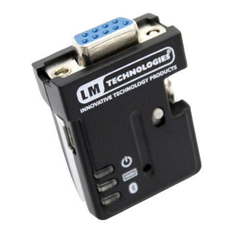
LM Technologies LM048 User manual

LM Technologies Ltd
Quick Start Guide
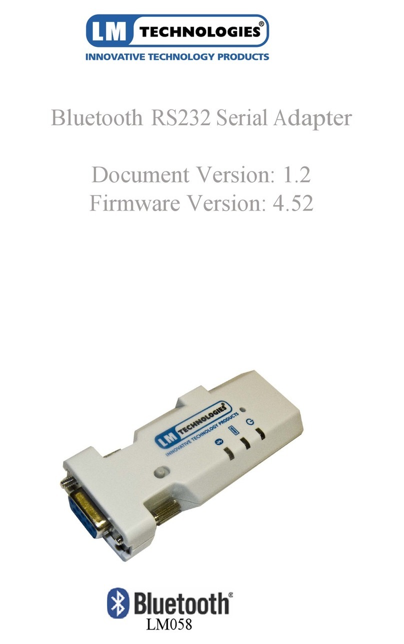
LM048 and LM058 Bluetooth Serial
Adapters
LM048 LM058
1Package Contents
Single Retail Pack Twin Retail Pack
1x Bluetooth Serial Adapter
1 x DB9 male to female connector
1 x USB – mini USB cable for power
1 x User Manual
1 x Warranty Card
1 x All in One PSU (UK, EU, US)
1 x 2dBi Antenna (LM058 only)
1
x CD with LM149 Configuration
Software
Optional:
1 x LM025 Slim Line 9 pin to 25 pin
converter
1x Bluetooth Serial Adapter
1 x DB9 male to female connector
1 x USB – mini USB cable for power
1 x User Manual
1 x Warranty Card
2 x All in One PSU (UK, EU, US)
2 x 2dBi Antenna (LM058 only)
1 x CD with LM149 Configuration
Software
Optional:
1 x LM025 Slim Line 9 pin to 25 pin
converter
2Setup
1. Connect LM048/LM058 to the serial port of the PC/Laptop. If the
PC or Laptop does not have serial port, a USB to Serial Converter
can be used.
2. Power the LM048/LM058 via the mini USB port using the mains
power supply or USB port of the PC. The connection to PC is
shown in diagram below

LM048/LM058 Quick Start Guide v1.3
©2012 LM- Technologies Ltd www.lm-technologies.com Page 2 of 8
3. Make sure the LM149 Software is installed on the PC. Alternatively
you can also use a serial terminal program like Hyperterminal,
Putty or Teraterm to configure the adapter using AT Commands.
For complete list of AT Command refer LM048&LM058 User
Manual.
4. Launch the LM149 Software, select the correct COM Port and
Serial Port Settings and press “Read Settings”. The default serial
settings on LM048 and LM058 are 19200 8 N 1 Flow: None.
For the old v4.5x series firmware, the default serial settings are
19200 8 N 1 Flow: Hardware.
5. If the user doesn’t know the serial settings on the adapter, then
LM149 Software will try all serial settings and find the correct
settings. Once the communication with the adapter is established
the LM149 Window will be populated with the settings as shown
below
6. Once the communication has been established, user is free to
change the settings on the window and press “Save Settings”. This
will save the modified settings to the adapter.
7. After the settings are saved, the adapter can be plugged to any
serial device and will work as a standalone plug and play unit.

LM048/LM058 Quick Start Guide v1.3
©2012 LM- Technologies Ltd www.lm-technologies.com Page 3 of 8
3Cannot communicate with the adapter?
If for some reason, the communication with the adapter cannot be
established, the LM149 software will give error “Initialization failed” as
shown below.
If this happens check the following
•The COM port number is correct.
•The connection between the serial cable and adapter is NOT loose.
•The serial cable is not faulty.
•Slide Switch Setting: The slide switch setting is dependent on the
serial cable used. The different combinations are shown below
Serial Device/Cable
Type
Adapter
Slide Switch Position
Straight LM048
Towards RS232
connector
LM058 v6.5x
firmware
Away from RS232
connector
LM058 v4.5x
firmware
Towards RS232
connector
Twisted/NULL Modem LM048 Away from RS232
connector
LM058 v6.5x
firmware
Towards RS232
connector
LM058 v4.5x
firmware
Away from RS232
connector
LM060
(LM Technologies USB-
Serial Converter)
LM048
Towards RS232
connector
LM058 v6.5x
firmware
Away from RS232
connector
LM058 v4.5x
firmware
Towards RS232
connector
Note: To check firmware version on LM058, check the sticker on
the back. For v6.5x firmware it will mention firmware v6.5x.
Otherwise it is v4.5x firmware.
If you are unsure of the cable used, try both slide switch positions.

LM048/LM058 Quick Start Guide v1.3
©2012 LM- Technologies Ltd www.lm-technologies.com Page 4 of 8
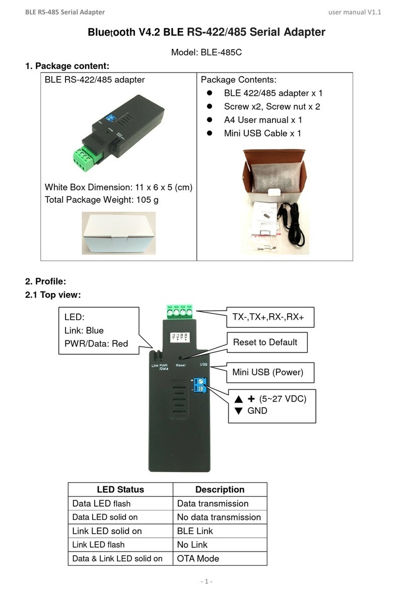
•The LED Status should be as below
POWER (RED) DATA (AMBER/GREEN) LINK (BLUE)
ON OFF BLINKING
OR
ON OFF OFF
If the BLUE LED is solid, then power off and power ON the adapter
or RESET the adapter by pressing RESET pin for 3 seconds. The
BLUE LED should be either blinking or switched off.
•Restore Factory Settings: If the communication is not established
even after checking the above points, then restore the factory
settings by pressing the reset button with a sharp object for 3
seconds. The 3 LEDs on the adapter will blink 3 times after restore
factory settings is successful. Try the LM149 Software after
selecting the factory serial settings and communicate again.
•If none of the above work, then contact LM Technologies at
support@lm-technologies.com
4Pairing the Adapters
A pair of LM048 or LM058 adapters can be configured to connect to each
other automatically when powered ON. In this mode, the adapters work as
serial cable replacement solution. LM149 software can be used to pair 2
adapters with each other. The steps are described below.
1. Setup the 1st adapter with PC/Laptop as described in Section 2
2. Click the pairing button on LM149 Software to go to pairing
window. Click “Pair Device” button. A message will pop up to
connect Device 2 to the COM port. Plug out the 1st adapter and
connect the 2nd adapter to the serial port and press OK.
3. A window will pop up to connect the 1st adapter back to the COM
port. Connect the 1st adapter back and press OK. The Device1 and
Device 2 Name and address will be read as highlighted below.

LM048/LM058 Quick Start Guide v1.3
©2012 LM- Technologies Ltd www.lm-technologies.com Page 5 of 8
4. After you connect the Device 1 to COM port and press OK, a
“pairing completed successfully” message will pop up.
5. If pairing fails, reset both adapters and start pairing again. In case
of further issues contact LM Technologies at support@lm-
technologies.com
5Application Setup
A pair of LM048 or LM058 adapters can be used as serial cable
replacement solution. However these adapters can also be used with a
Bluetooth enabled PC, Laptop, Smartphone, PDA or Tablet.
When used with a PC/Laptop, a virtual Bluetooth Serial Port will be
created when service discovery is done on the adapter. Opening the virtual

LM048/LM058 Quick Start Guide v1.3
©2012 LM- Technologies Ltd www.lm-technologies.com Page 6 of 8
serial port will create a Bluetooth connection and then communication can
be done by sending and receiving data on the virtual serial port.
With a Smartphone, PDA or Tablets, the behavior varies from device to
device. On a WinCE or Windows Mobile device, a virtual serial port may be
created just like on Windows. On Android, Blackberry, JAVA devices, a
customized application can be developed to communicate with the
adapters. Communication with iPhone/iPad is not supported yet because a
special chip called MFI chip is required on any accessory communicating
with Apple devices. LM048/LM058 does not include the MFI chip at the
moment. For further information on the roadmap to support Apple
products, contact LM Technologies at development@lm-technologies.com
5.1 Serial Cable Replacement Solution Example
The illustration here describes a serial cable replacement solution between
a serial printer and PC. However this example can be expanded to any 2
devices which have a serial port like a CNC Machine and CNC Controller or
Data logger and PC etc.
The following steps describe setting up a pair of adapters as a serial cable
replacement between a PC and Serial Printer.
1. Pair the adapters together as explained in Section 4.
2. Make sure the printer has got a 9 pin serial port connector or a 25
pin to 9 pin converter.
3. Check the specification of the printer for the serial port settings.
Most of the serial printers use 9600 8 N 1 flow: None.
4. Configure both adapters to the same serial settings as the printer
using the LM149 Software. In this case the settings will be 9600:
baud rate, none: parity, 1: stop bit, none: flow control. Disable the
command response on both adapters to avoid ASCII string
“CONNECT”/”DISCONNECT” print during connection and
disconnection.
5. On the PC install the printer driver on the Serial Port where the
serial adapter will be connected.
6. One adapter is connected to the serial port of the PC and the other
adapter is connected to the serial port of the printer. If the printer
does not provide power on Pin 9, then an external power supply
may be required.
7. When both adapters are powered, they should automatically
establish Bluetooth connection to each other. Blue LEDs will turn
solid ON.
8. After the adapters have established connection, send a test print
from the PC. It should be printed on the printer.
9. If there is no print, try changing the slide switch on the adapter
connected to printer and check if it resolves the problem?
10. If there is still no print, then there is a serial settings mismatch
between the printer and adapter or the PC and adapter. Please
recheck the settings or consult printer manual.
11. If still unable to communicate, contact LM Technologies at
support@lm-technologies.com

LM048/LM058 Quick Start Guide v1.3
©2012 LM- Technologies Ltd www.lm-technologies.com Page 7 of 8
PRINTER LM058
PC LM058
6FCC Warning Statement
This device complies with Part 15 of the FCC Rules. Operation is subject to
the following two conditions:
1) This device may not cause harmful interference, and
2) This device must accept any interference received, including
interference that may cause undesired operation
This equipment has been tested and found to comply with the limits for a
class B digital device, pursuant to part 15 of the FCC Rules. These limits are
designed to provide reasonable protection against harmful interference in
a residential installation. This equipment generates, uses and can radiate
radio frequency energy and, if not installed and used in accordance with
the instructions, may cause harmful interference to radio communications.
However, there is no guarantee that interference will not occur in a
particular installation. If this equipment does cause harmful interference
to radio or television reception, which can be determined by turning the
equipment off and on, the user is encouraged to try to correct the
interference by one or more of the following measures:
• Reorient or relocate the receiving antenna.
• Increase the separation between the equipment and receiver.
• Connect the equipment into an outlet on a circuit different from that to
which the receiver is connected.
• Consult the dealer or an experienced radio/TV technician for help.
Installation and use of this device must be in strict accordance with the
instructions included in the user documentation provided with the
product. Any changes or modifications (including the antennas) made to
this device that are not expressly approved by the manufacturer may void
the user’s authority to operate the equipment. The manufacturer is not
responsible for any radio or television interference caused by

LM048/LM058 Quick Start Guide v1.3
©2012 LM- Technologies Ltd www.lm-technologies.com Page 8 of 8
unauthorized modification of this device, or the substitution of the
connecting cables and equipment other than manufacturer specified. It is
the responsibility of the user to correct any interference caused by such
unauthorized modification, substitution or attachment. Manufacturer and
its authorized resellers or distributors will assume no liability for any
damage or violation of government regulations arising from failing to
comply with these guidelines.
This equipment complies with FCC radiation exposure limits set forth for
an uncontrolled environment. This transmitter must not be co-located or
operating in conjunction with any other antenna or transmitter.
7Revision History
Version Date Description
v1.0 22-03-2012 First Version
v1.1 30-03-2012 1.
Updated slide switch settings point in
Section 3 to include LM060 (USB-
Serial Converter)
2. Added Revision History
v1.2 05-04-2012 1.
Added slide switch setting for LM058
with v4.5x firmware in Section 3
v1.3 25-06-2012 1. Add FCC Warning Statement

X-ON Electronics
Largest Supplier of Electrical and Electronic Components
Click to view similar products for LM Technologies manufacturer:
Other Similar products are found below :
LM400 LM832-0476 LM910-0630 LM930-0635 LM931-0552 LM506 LM1010-0970 530-0653 530-0654 LM254 LM780 LM252
LM072-3115 LM253 LM251 LM822-1459
Other manuals for LM048
3
This manual suits for next models
1
Table of contents
Other LM Technologies Adapter manuals

LM Technologies
LM Technologies LM540 User manual

LM Technologies
LM Technologies LM506 User manual

LM Technologies
LM Technologies LM048 Installation manual

LM Technologies
LM Technologies LM320 User manual

LM Technologies
LM Technologies LM048v2 User manual

LM Technologies
LM Technologies LM809-0647 User manual

LM Technologies
LM Technologies LM006 User manual

LM Technologies
LM Technologies RS232 User manual

LM Technologies
LM Technologies LM1010 User manual

LM Technologies
LM Technologies LM505 User manual