LoadSurfer WH-25ES User manual
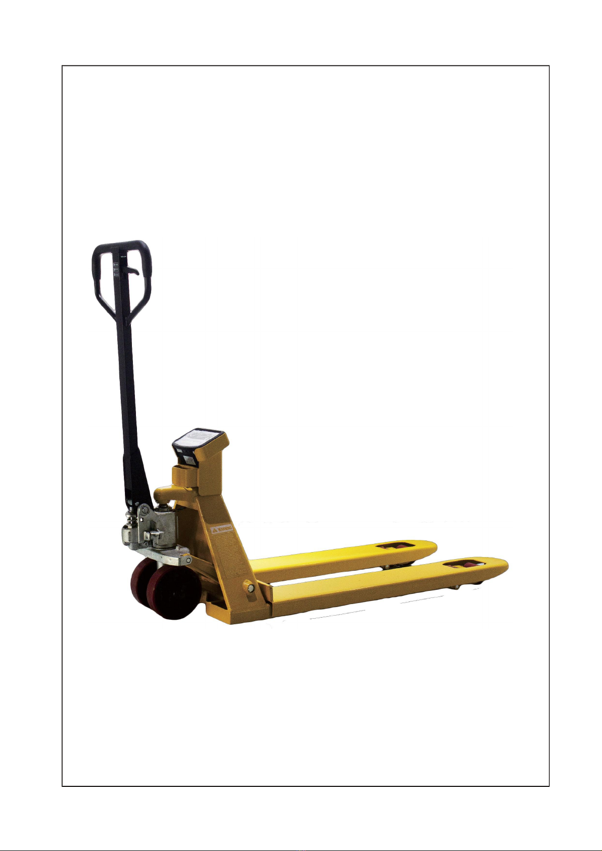
InstructionManual
Pallet Truck with Scale
Note: Owner/Operatormust read and understand this instruction
manualbeforeusingthe pallettruckwithscale.

2
Thank you for using this hand pallet truck with scale. For your safety and correct operation of the scale, please
read these instructions carefully before using it.
NOTE: (1) All of the information reported herein is based on data available at the moment of printing. The
factory reserves the right to modify its own products at any moment without notice and incurring
any sanction. So it is suggested to always verify possible updates.
(2)Prior to use this hand pallet truck with scale, the battery of scale must be charged enough.
1. GENERALSPECIFICATIONS
Model
Capacity
Graduation
Weighing
Accuracy
Forksize
Length
Outerforkwidth
ForkWidth
WH-25/30ES
2500/ 3000kg
0.5kg
± 0.05%
1150mm
540mm
160mm
WH-25/30ES
2500/ 3000kg
0.5kg
± 0.05%
1220mm
685mm
160mm
Materials and specifications are subject to change without notice.
2. TOATTACHHANDLETO PUMPUNIT
2.1 Remove the handle component (H100), insert it into the pump shell (P06).
2.2 Remove the axle from plastic bag(P07)
2.3 Insert the axle (P07) at one end of the pump shell(P06), then pump shell (P06) and handle components
(H100) connection. Please note axle (P07) the position of the hole, Let the steel wire and nut on the chain
(H09) through the axle (P07) hole (See the hydraulic system diagram and the handle component diagram).
2.4 Spring pin (P08) fixed the axle(P07).
2.5 Handle (H01) press the pump plunger(P21), and remove the pin(P09).
2.6 Raise the crank link (P48) and put the pin on rod and chain (H09) into the groove of crank link (P48).
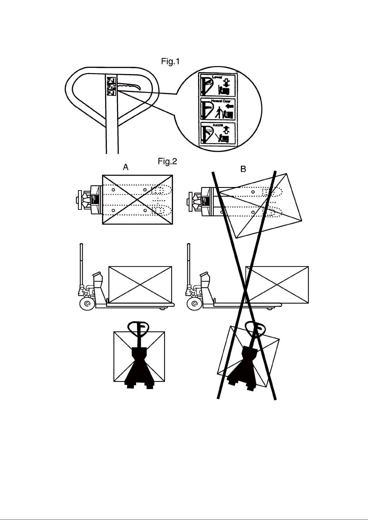
3. TOADJUSTRELEASEDEVICE
On the handle of the pallet truck, you will find the control lever (H01) which can be set in three positions
(See Fig. 1): LOWER=to lower the forks; NEUTRAL=to move the load; ASCENT=to raise the forks. After
assembling the handle, you can adjust the three positions.
3.1 First tighten the setting screw (P50) on the crank link (P48) until the LOWER position function works.
3.2 If the forks elevate while pumping in the NEUTRAL position, turn the setting screw (P50) clockwise until
pumping the handle does not raise the forks andthe NEUTRAL position functions correctly.
3.3 If the forks descend while pumping in the NEUTRAL position, turn the setting screw (P50)
counter-clockwise until the forks do not lower.
3.4 If the forks do not descend when the control lever (H01) is in the LOWER position, turn the setting screw
(P50) clockwise until raising the control lever (H01) lowers the forks. Then check the NEUTRAL position
as per item 4.2 and 4.3.
3.5 If the forks do not lift while pumping in the ASCENT position, turn the setting screw (P50) counter-
clockwise until the forks elevate while pumping in the ASCENT position. Then check the NEUTRAL and
LOWER position as per item 4.2, 4.3 and 4.4.
4. MAINTENANCE
4.1 OIL
Please check the oil level every six months. Total oil amount is about 260 ml, add injection oil 50-100 ml,
this must be with the forks in the lowered position.
Add or change the hydraulic oil according to the table below.
Temperature
Oil
-20℃~+40 ℃
L-HV46 Hydraulic oil

3
4.2 HOW TO EXPEL AIR FROM THE PUMP UNIT
Air may enter the unit when the seals are replaced. Lift the control lever (H01) to the LOWER position, then
move the handle up and down for several times.
4.3 DAILY CHECK AND MAINTENANCE
Daily check of the pallet truck can limit wear and tear of the unit. Pay special attention to the wheels (P34,
AF06), the axles (AF08, AF10, AF15), the handle (H01), the forks (AF01) and lift and lower control.
4.4 LUBRICATION
Use motor oil or grease to lubricate all moveable parts.
5. GUIDETO SAFEOPERATION
For safe operation of the truck, please read all warning signs and instructions here and on the truck before
using this truck.
5.1 Do not operate the pallet truck unless you are familiar with it and have been trained or authorised to do
so.
5.2 Do not operate the truck unless you have checked its condition. Give special attention to the wheels,
the handle assembly, the forks, lift and the lower control.
5.3 Do not use the truck on sloping ground.
5.4 Never place any part of your body in the lifting mechanism or under the forks or load. Do not carry
passengers.
5.5 The operator should wear gloves and safety shoes for protection.
5.6 Do not handle unstable or loosely stacked loads.
5.7 Do not overload the truck.
5.8 Do not subject to unbalanced load, either side to side or along the length of the frame (refer to Fig. 2/B).
5.9 The capacity of the truck assumes an evenly distributed load with the centre of the load being at the
halfway point of the length of the forks (refer to Fig. 2)
5.10 Make sure that length of the forks matches the length of the pallet.
5.11 Lower the forks to lowest height when the truck is not being used.
5.12 At other specific conditions or places, the operator should operate the pallet truck carefully.
6. TROUBLESHOOTING
NO
TROUBLE
CAUSE
ACTION
1
The forks do not lift
to maximum height.
-Not enough hydraulic oil.
-Add more oil.
2
The forks do not lift
up.
-Not enough hydraulic oil.
-The oil has impurities.
-Discharge valve is out of
adjustment.
-Air in the hydraulic oil.
-Pour in more filtered oil.
-Change the oil.
-Adjust the setting screw (P50).
-Expel the air.
3
The forks do not
descend.
-The rod (P101) and the pump
cover (P02) are deformed
resulting from a seriously
unbalanced load.
-A part has been broken or
been deformed resulting from
unbalanced load.
-The setting screw (P50) is not
in the correct position.
-Replace the rod (P02) or pump
cover (P101).
-Repair or replace component.
-Adjust the setting screw (P50).

4
4
Leaks
-Seals worn out or damaged.
-Some parts may be cracked or
worn out.
-Replace seals with new ones.
-Check and replace with new
ones.
5
The forks
without
lowered.
descend
being
-Impurities in the oil cause the
discharge valve (B) to fail to
close.
-Air in the oil.
-Seals worn or damaged.
-Discharge valve (B) is out of
adjustment.
-Replace with filtered oil.
-Expel the air.
-Replace with new ones.
-Adjust the setting
(P50H).
screw
7. WEIGHINGOPERATION
7.1 Put the control lever in the LOWER position and lower the truck to lowest position.
7.2 Press the key to turn the system on. After the start-up sequence the indicator will display the weight.
7.3 Weighing method for gross weight::
Press the ZERO key to set the gross weight to 0. Put the forks under the pallet and check that the load
is properly balanced. Put the control lever in the ASCENT position, pump the handle to make the forks
rise until the pallet has left the ground. When the indicator is stable, the gross weight of the goods (total
weight of the pallet and the goods) is shown.
7.4 Weighing method for net weight:
To display the weight of the goods without the weight of the pallet (or other container):
7.4.1 Weigh single standard pallet, for example: weight of pallet: 40kg.
7.4.2 Press the ZERO key, the indicator will display “0kg”.
7.4.3 Remove the pallet from the forks, the indicator will display “-40kg ”.
7.4.4 Weigh the goods on the pallet as shown in 7.3, when the indicator is stable, the net weight of the goods
is shown.
7.5 Switch between kg and lb.
When the weight is shown in kg’s, Press on the ZERO key will soon be kg to switch to the pound.
Press on the ZERO key again and the unit shown will switch back to kg.
7.6 Turn off the Indicator
Press on the ON /OFF key until the indicator displays “OFF ”. Releasing the key will turn off the
indicator.
8. BATTERYPOWERDATAANDREPLACEMENT
8.1 How to change batteries:
8.1.1 Loosen the screws on the battery cover and remove the cover.
8.1.2 open the screw on battery and pull out battery ,out the socket.
8.1.3 put the new battery and insert the socket.
8.1.4 Screw the battery cover plate back into position.
5
6
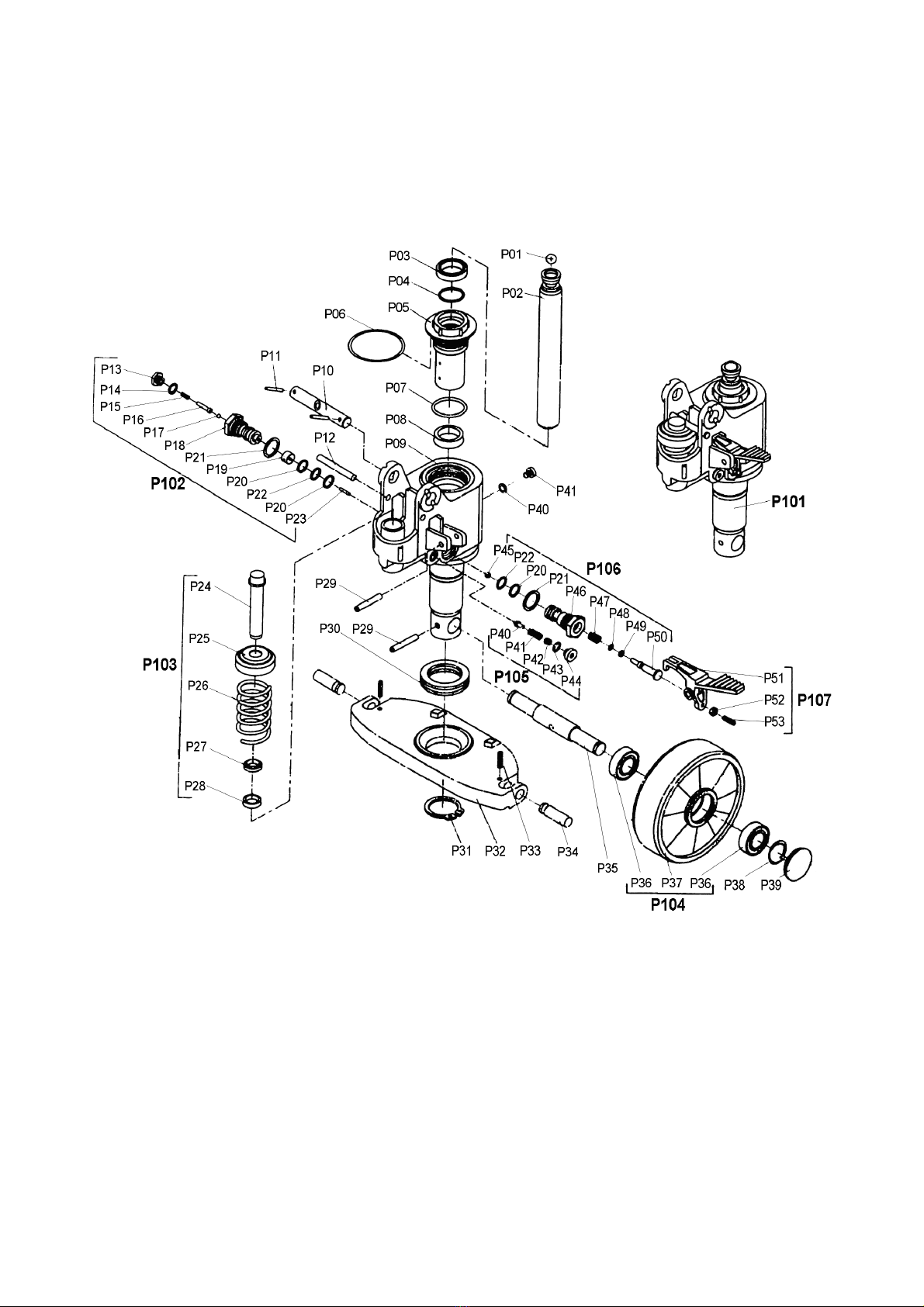
PARTS DRAWING OF PUMP ASSEMBLY

7
PARTS LIST OF PUMP ASSEMBLY
8
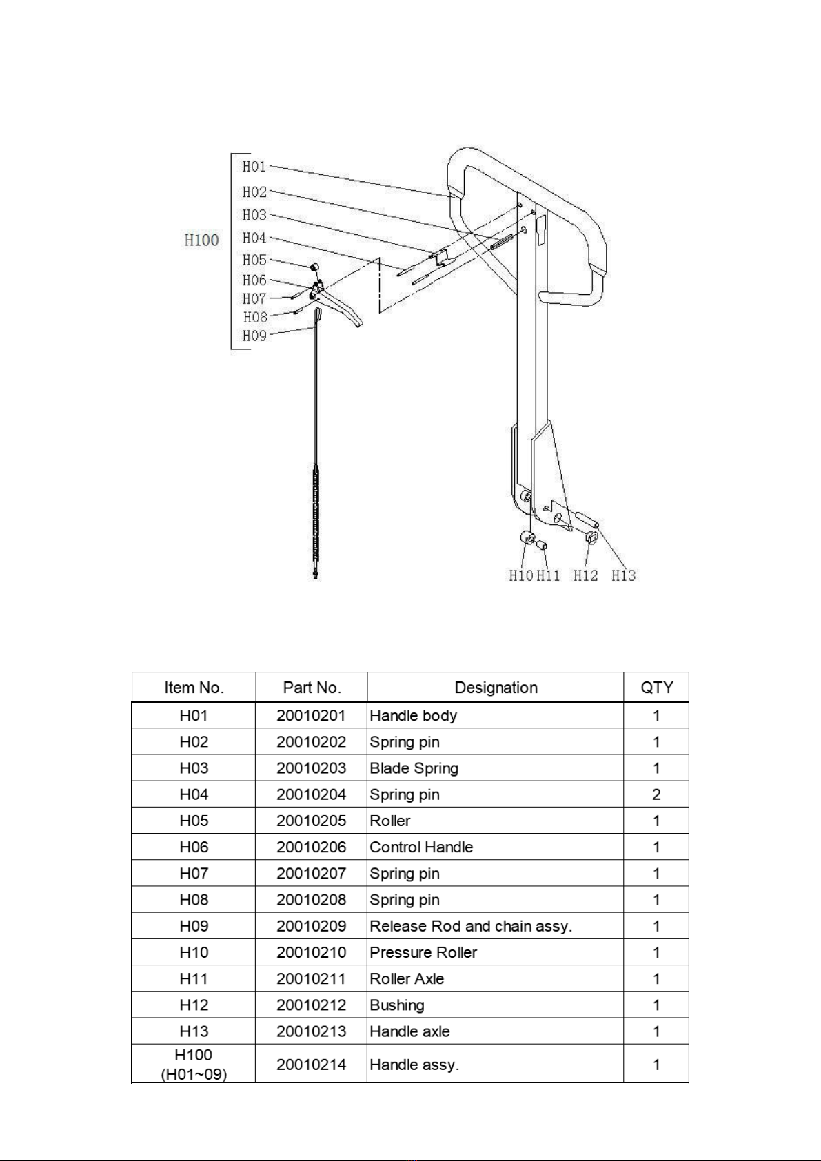
PARTS DRAWING OF HANDLE
PARTS LIST OF HANDLE

9
PARTS DRAWING OF FRAME
Meter printer configuration
A39
A40
A35L

10
PARTS LIST OF FRAME
11
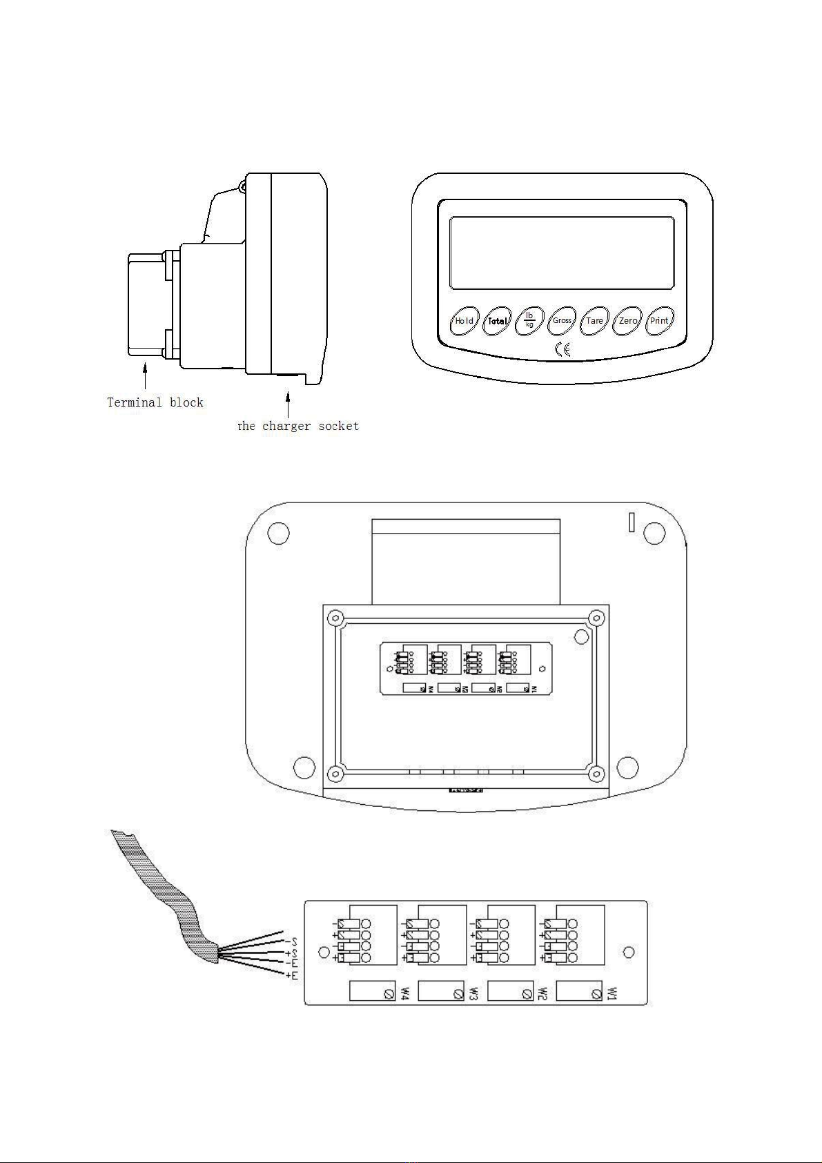
9. WIRING DIAGRAM OF SCALE, JUNCTION BOX, SENSOR
Instrument on the back, opened the box lid, wiring diagram

12
J1~J4
Connect
sensor
connector
-S
white
+S
green
-E
black
+E
red
10.CHANGINGTHEPAPER
10.1 Pull the lever to open the cover of the printer. Place the paper roll. Make sure the flap is at the top of the
printer, facing towards you. Hold on to the paper when closing the printer. Push the cover closed firmly.
11.TROUBLESHOOTINGOF WEIGHINGUNIT
NO
TROUBLE
CAUSE
SHOOTING
1
The instrument
shows ∶OVER
-The load is too big for the scale
-Remove the load immediately.
2
Textis notprinted
clearly on the
ticket
-Battery voltage is too low
-Charge the batteries.
3
The scale is not
accurate
-The fork shoe is touching the
bottom part of the scale
-Cable in junction box is loose.
-1 of the load cells is broken
-Remove anything that restricts the movement of
the scale.
-Check the connection in junction box after
confirming safe.
-Stand on the 4 corners of the scale. The load cell
in the corner with a different weight should be
replaced.
4
Indicatorcan’t be
turnedon.
-Battery voltage is too low.
-Battery life is complete.
-Charger is damaged.
-Charge the batteries.
-Replace rechargeable battery with new ones.
-Check charger output voltage replace charger
with new one.
5
Battery can’t be
charged.
-Battery is damaged.
-Charger is damaged.
-Replace rechargeable battery with new ones.
-Check charger output voltage replace charger
with new one.
This manual suits for next models
1
Table of contents


