Locinox SlimStone-X User manual

SlimStone-X 1
SlimStone-X
MANUAL • HANDLEIDING • MANUEL
ANLEITUNG •INSTRUCCIONES
INSTRUKCJA •ИНСТРУКЦИИ

2SlimStone-X
COPYRIGHT
Copyright©2021 Locinox. All rights reserved. This product incorporates copyright protected technology that is
protected by a number of EU patent method claims and other intellectual property rights owned by the Locinox
Corporation and other rightholders.
Use of this copyright protected technology must be authorized by the Locinox Corporation. Reverse engineering or
disassembly is prohibited.
No part of this publication can either be reproduced, communicated, transcribed, stored in a retrieval system or
be translated into any language in any form or by any means, whether electronic, mechanical, magnetic, optical,
chemical, manual or otherwise, unless explicit written consent has been given by the copyright holder.
NOTICE
The contents of this publication are subject to change. The Locinox Corporation reserves the right to alter the contents
of this publication at any time and without notice. The contents of this publication may contain inaccuracies or
typographical errors and is supplied for informational use only.
TECHNICAL SUPPORT
If you require any additional information or assistance during the installation, please contact your dealer, who will be
able to provide the latest information. Alternatively, you can visit the Locinox website for more technical information or
e-mail us on [email protected]. Please keep the serial number at hand of your product for future support.

SlimStone-X 3
SlimStone-X
MANUAL • HANDLEIDING
MANUEL • ANLEITUNG
INSTRUCCIONES • INSTRUKCJA
ИНСТРУКЦИИ

4SlimStone-X
Frost-free
with heating
element
Up to 400
entry codes
Ultimate
durable
components
SlimStone-X
Extreme
weather
proof
IP 68
Easily
readable
digits by
LED lighting
High
security
with
external
relays

SlimStone-X 5
BOX CONTENT
SLIMSTONE
27 mm
1-1/16”
Ø 15 mm
Ø 9/16”
Ø 15 mm
Ø 9/16”
50 mm
2”
115 mm
4-1/2””
*TEMP-000049*
50 mm
2”
115 mm
4-1/2”
137 mm
5-3/8”
54 mm
2-1/8”
23,8 mm
15/16”
1
5
2
3
4
1SlimStone-X
2Allen key 6 mm
3Allen key 2,5 mm
4Wall mounting set
5Drilling template

6SlimStone-X
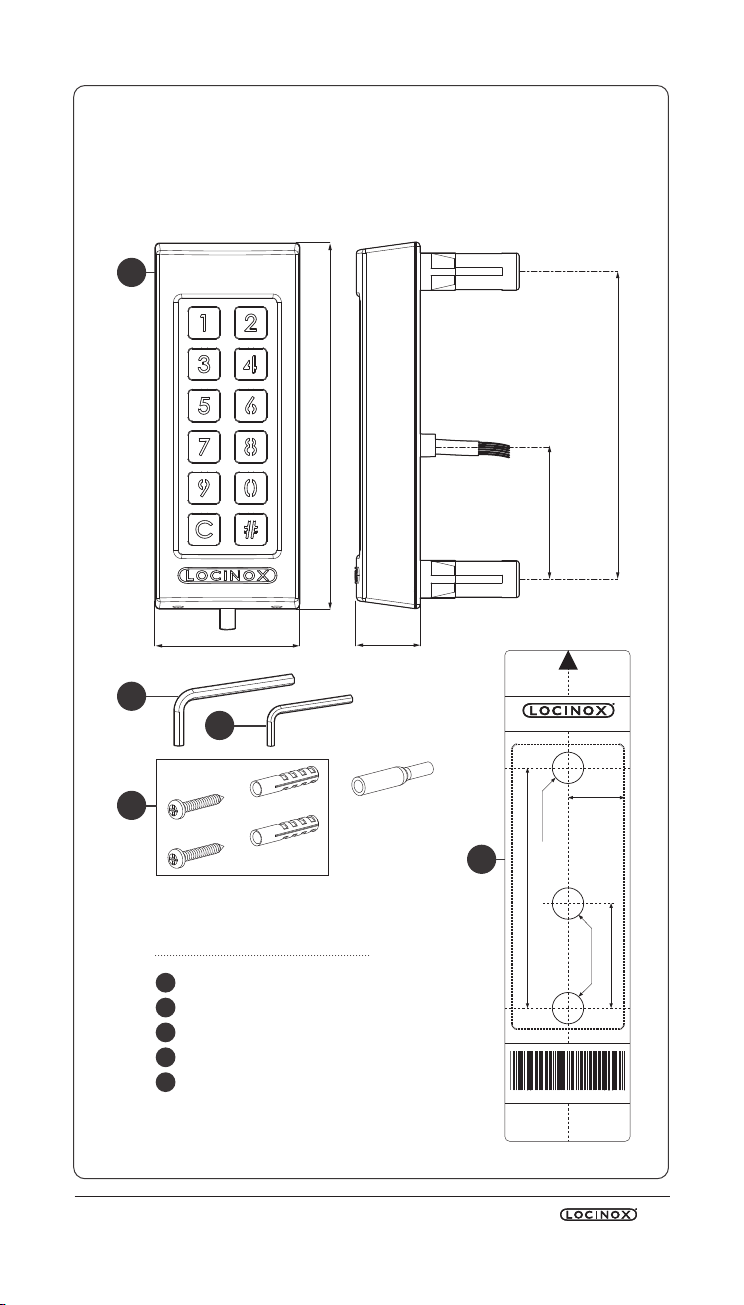
1. PRODUCT DESCRIPTION ...................................................................................................... 8
2. TECHNICAL SPECIFICATIONS............................................................................................. 8
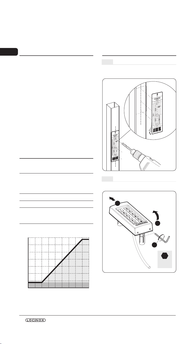
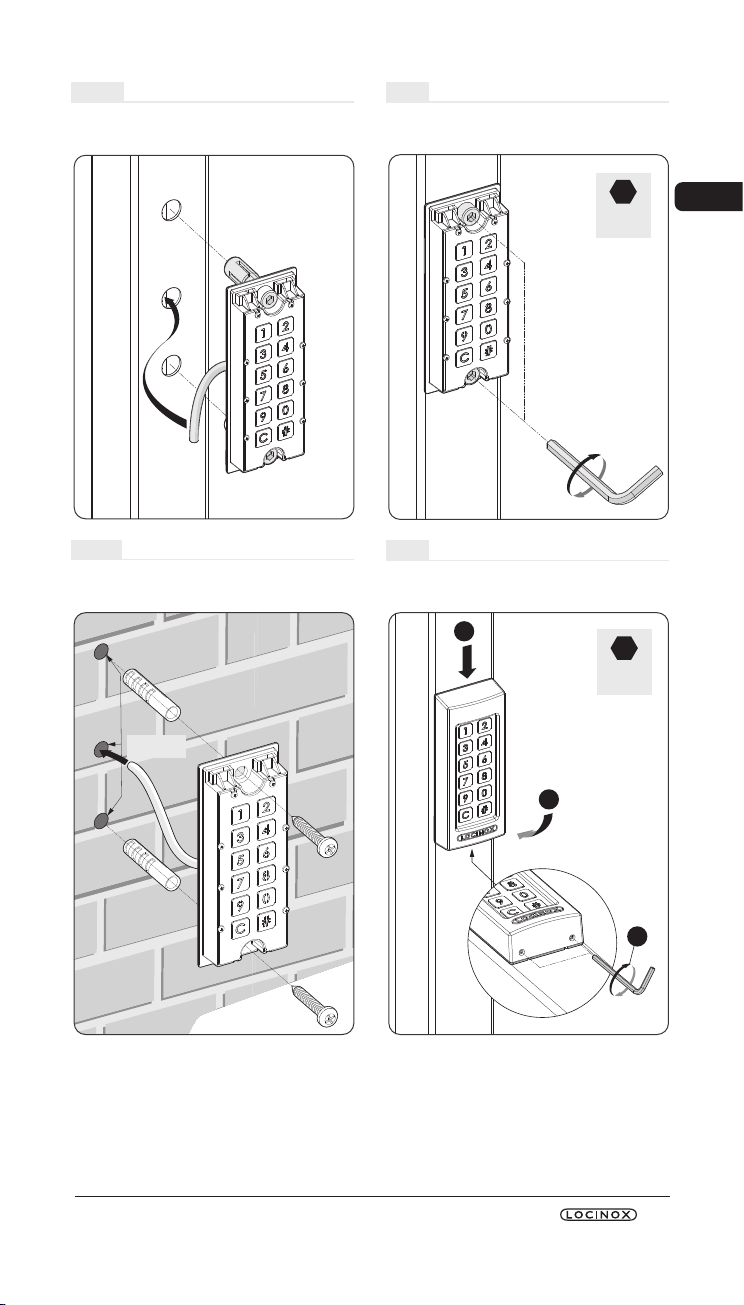
3. MOUNTING............................................................................................................................ 8
4. CABLING.................................................................................................................................. 10
5. SYSTEM INSTALLATION........................................................................................................ 10
6. CONTROL INPUTS.................................................................................................................. 11
7. P R O G R A M M I N G .................................................................................................................... 11
8. FACTORY RESET UPON LOSS OF MASTER PIN ................................................................. 13
9. REPLACING A SLIMSTONEX ............................................................................................... 13
10. REPLACING A SWITCHSTONESTD.................................................................................... 14
11. FUNCTIONING OF SLIMSTONEX...................................................................................... 14
12. MAINTENANCE...................................................................................................................... 14
13. GENERAL INFORMATION.................................................................................................... 14
14. WARRANTY ............................................................................................................................. 14
15. TROUBLESHOOTING............................................................................................................. 15
16. FREQUENTLY ASKED QUESTIONS...................................................................................... 15
USER CODES........................................................................................................................... 64
CONNECTION SCHEME...................................................................................................... 70
1. PRODUCTBESCHRIJVING..................................................................................................... 16
2. TECHNICAL SPECIFICATIONS............................................................................................. 16
3. MONTAGE............................................................................................................................... 16
4. BEKABELING........................................................................................................................... 18
5. SYSTEEMINSTALLATIE ........................................................................................................... 18
6. VOORRANGSCONTACTEN ................................................................................................. 19
7. PROGRAMMERING ............................................................................................................... 19
8. RESET FABRIEKSINSTELLINGEN BIJ VERLIES VAN MASTERPINCODE ........................ 21
9. EEN SLIMSTONEX VERVANGEN........................................................................................ 21
10. EEN SWITCHSTONESTD VERVANGEN............................................................................. 22
11. WERKING VAN DE SLIMSTONEX....................................................................................... 22
12. ONDERHOUD......................................................................................................................... 22
13. ALGEMENE INFORMATIE..................................................................................................... 22
14. GARANTIE ............................................................................................................................... 22
15. PROBLEEMOPLOSSING ........................................................................................................ 23
16. VEELGESTELDE VRAGEN....................................................................................................... 23
GEBRUIKERSCODES .............................................................................................................. 64
AANSLUITSCHEMA ............................................................................................................... 70
1. DESCRIPTION DU PRODUIT.................................................................................................. 24
2. TECHNICAL SPECIFICATIONS............................................................................................. 24
3. MONTAGE............................................................................................................................... 24
4. CÂBLAGE................................................................................................................................. 26
5. INSTALLATION DU SYSTÈME ............................................................................................... 26
6. CONTACT PRIORITAIRE......................................................................................................... 27
7. PROGRAMMATION............................................................................................................... 27
8. RÉINITIALISATION D’USINE EN CAS DE PERTE DU CODE
PIN PRINCIPAL ........................................................................................................................ 29
9. REMPLACEMENT D’UN SLIMSTONEX............................................................................... 29
10. REMPLACEMENT D’UNSWITCHSTONESTD..................................................................... 30
11. FONCTIONNEMENT DU SLIMSTONEX............................................................................ 30
12. ENTRETIEN............................................................................................................................... 30
13. INFORMATIONS GÉNÉRALES............................................................................................. 30
14. GARANTIE ............................................................................................................................... 30
15. AIDE AU DÉPANNAGE........................................................................................................... 31
16. QUESTIONS FRÉQUEMMENT POSÉES .............................................................................. 31
CODES D’UTILISATEUR.......................................................................................................... 64
SCHÉMA DE CONNEXION.................................................................................................. 70
1. PRODUKTBESCHREIBUNG................................................................................................... 32
2. TECHNISCHE SPEZIFIKATIONEN ....................................................................................... 32
3. MONTAGE............................................................................................................................... 32
4. VERKABELUNG....................................................................................................................... 34
5. INSTALLATION DES SYSTEMS.............................................................................................. 34
6. STEUEREINGÄNGE................................................................................................................ 35
7. PROGRAMMIERUNG............................................................................................................. 35
8. ZURÜCKSETZEN AUF WERKSEINSTELLUNGEN BEI VERLUST
DES MASTERPINCODES..................................................................................................... 37
9. AUSTAUSCH EINER SLIMSTONEX ..................................................................................... 37
10. AUSTAUSCH EINES SWITCHSTONESTD .......................................................................... 38
11. FUNKTIONSWEISE DER SLIMSTONEX.............................................................................. 38
12. WARTUNG............................................................................................................................... 38
13. ALLGEMEINE INFORMATIONEN........................................................................................ 38
14. GARANTIE ............................................................................................................................... 38
15. FEHLERBEHEBUNG................................................................................................................. 39
16. HÄUFIG GESTELLTE FRAGEN................................................................................................ 39
BENUTZERCODES.................................................................................................................. 64
VERBINDUNGSSCHEMA...................................................................................................... 70
EN
NL
FR
DE
CONTENTS

SlimStone-X 7
1. DESCRIPCIÓN DEL PRODUCTO........................................................................................... 40
2. ESPECIFICACIONES TÉCNICAS.......................................................................................... 40
3. MONTAJE ................................................................................................................................ 40
4. CABLEADO .............................................................................................................................. 42
5. INSTALACIÓN DEL SISTEMA................................................................................................ 42
6. ENTRADAS DE CONTROL ..................................................................................................... 43
7. P R O G R A M A C I Ó N .................................................................................................................. 43
8. RESTABLECIMIENTO DE FÁBRICA TRAS PÉRDIDA DEL PINMAESTRO........................... 45
9. SUSTITUCIÓN DE UN SLIMSTONEX ................................................................................. 45
10. SUSTITUCIÓN DE UN SWITCHSTONESTD...................................................................... 46
11. FUNCIONAMIENTO DEL SLIMSTONEX............................................................................ 46
12. MANTENIMIENTO................................................................................................................. 46
13. INFORMACIÓN GENERAL................................................................................................... 46
14. GARANTÍA............................................................................................................................... 46
15. RESOLUCIÓN DE PROBLEMAS............................................................................................ 47
16. PREGUNTAS FRECUENTES.................................................................................................... 47
CÓDIGOS DE USUARIO........................................................................................................ 64
ESQUEMA DE CONEXIÓN................................................................................................... 70
1. OPIS PRODUKTU .................................................................................................................... 48
2. DANE TECHNICZNE.............................................................................................................. 48
3. INSTALACJA ............................................................................................................................ 48
4. PRZEWODY PODŁĄCZENIOWE .......................................................................................... 50
5. INSTALACJA SYSTEMU.......................................................................................................... 50
6. PRZEKAŹNIKI PRIORYTETOWE............................................................................................ 51
7. PROGRAMOWANIE............................................................................................................... 51
8. PRZYWRACANIE USTAWIEŃ FABRYCZNYCH W RAZIE UTRATY
GŁÓWNEGO KODU PIN....................................................................................................... 53
9. WYMIANA SLIMSTONEX .................................................................................................... 53
10. WYMIANA SWITCHSTONESTD......................................................................................... 54
11. OBSŁUGA URZĄDZENIA SLIMSTONEX ............................................................................ 54
12. KONSERWACJA...................................................................................................................... 54
13. INFORMACJE OGÓLNE........................................................................................................ 54
14. GWARANCJA.......................................................................................................................... 54
15. ROZWIĄZYWANIE PROBLEMÓW....................................................................................... 55
16. CZĘSTO ZADAWANE PYTANIA ........................................................................................... 55
KODY UŻYTKOWNIKÓW...................................................................................................... 64
SCHEMAT PODŁĄCZENIA.................................................................................................... 70
1. ОПИСАНИЕ ПРОДУКТА ...................................................................................................... 56
2. ТЕХНИЧЕСКИЕ ХАРАКТЕРИСТИКИ.................................................................................... 56
3. МОНТАЖ ................................................................................................................................. 56
4. КАБЕЛЬНОЕ ПОДКЛЮЧЕНИЕ ........................................................................................... 58
5. УСТАНОВКА СИСТЕМЫ....................................................................................................... 58
6. ВХОДЫ УПРАВЛЕНИЯ........................................................................................................... 59
7. ПРОГРАММИРОВАНИЕ ....................................................................................................... 59
8. СБРОС ДО ЗАВОДСКИХ НАСТРОЕК ПРИ УТЕРЕ
КОНТРОЛЬНОГО ПИНКОДА ............................................................................................ 61
9. ЗАМЕНА SLIMSTONEX........................................................................................................ 61
10. RЗАМЕНА SWITCHSTONESTD........................................................................................... 62
11. ФУНКЦИОНИРОВАНИЕ SLIMSTONEX ........................................................................... 62
12. ОБСЛУЖИВАНИЕ ................................................................................................................. 62
13. ОБЩАЯ ИНФОРМАЦИЯ...................................................................................................... 62
14. ГАРАНТИЯ................................................................................................................................ 62
15. УСТРАНЕНИЕ НЕИСПРАВНОСТЕЙ .................................................................................... 63
16. ЧАСТО ЗАДАВАЕМЫЕ ВОПРОСЫ..................................................................................... 63
КОДЫ ПОЛЬЗОВАТЕЛЕЙ .................................................................................................... 64
СХЕМА ПОДКЛЮЧЕНИЯ..................................................................................................... 70
ES
PL
RU

EN
8SlimStone-X
Congratulations with the purchase
of your SlimStone-X
1. PRODUCT DESCRIPTION
The SlimStone-X is a sturdy, weather resistant
keypad with integrated led lighting. This keypad
is unique in its kind thanks to its durability.
Developed and tested for use in the most extreme
weather conditions, SlimStone-X guarantees
access control in all circumstances.
The SlimStone-X should be combined with the
SwitchStone-STD. This is a 2-channel relay
module, containing a Common, Normally Open
and Normally Closed contact for each relay. Both
relays can be used to control Locinox or 3rd party
devices. Equipped with the innovative
Quick-Fix, alternative fixings for wood and stone
are supplied as well.
The SlimStone-X is made of an aluminium powder
coated housing with a brushed stainless steel key
panel and likewise push buttons.
Up to 400 codes can be programmed.
2. TECHNICAL SPECIFICATIONS
Operational
temperature
-30°C up to 85°C
-22°F up to 185°F
Power supply Use in combination
with the Locinox PowerStone
or the Locinox
DC-POWER 24V/25W
Cable length 2 m (6-1/2ft)
IP value IP68
Consumption 1,5 W (> 5°C/41°F) +
12 W at max heating
(< -25°C/ < -13°F)
3. MOUNTING
STEP 1
Stick the template and drill into the wall or post (see
p.5).
STEP 2
Remove the cover of the SlimStone-X.
1
3
2
HEX
2,5 mm
INTERNAL TEMPERATURE °C
-22-13-451423
32
415059
-30-25-20-15-10-5
0
51015
0
2
4
6
8
10
12
14
CONSUMPTION W
INTERNAL TEMPERATURE °F
HEATING

EN
SlimStone-X 9
STEP 3A
Run the cable through the middle hole in the post.
STEP 3B
Run the cable through the middle hole in the wall.
3x Ø 10 mm
3x 3/8"
STEP 4
Position the SlimStone-X and tighten both
Quick-Fix.
STEP 5
Position the cover and tighten using
2 screws underneath.
1
2
3
HEX
2,5 mm
HEX
6 mm

EN
10 SlimStone-X
4. CABLING
The SlimStone-X is equipped with a 2m long 2
conductor cable.
See p.70 for a detailed connection scheme.
4.1 SYSTEM WIRING
Only copper cabling should be used for wiring the
system. The required cable diameter depends on
the maximum distance between the PowerStone/
DC-POWER 24V/25W and the furthest device in the
installation:
Maximum
one-way
distance between
PowerStone and
furthest device in the
network
Minimum cable section
25 m 0.2 mm2(AWG24)
100 m 0.75 mm2
(AWG 18)
300 m 1.5 mm2(A W G 15 )
Both the PowerStone or DC-POWER 24V/25W can
be used to power a network
+_
IN1
C
C
NO
NO
NC
NC R2
R1
RELAY 1
RELAY 2
BUS BUS
IN2
BUS 24V DC
AUX BUS 24V
L N
POWER
OVERLOAD
Wiring when using a PowerStone
IN1
C
C
NO
NO
NC
NC R2
R1
24V 220V
RELAY 1
RELAY 2
BUS
L N
DC-POWER 24V/25W
Wiring when using a DC-POWER 24V/25W
BUS
IN2
Bus wires have no polarity: there is no need
to take polarity (+ or -) into account when
connecting cables
4.2 SWITCHSTONESTD
DETAILED WIRING
IN1
C
C
NO
NO
NC
NC R2
R1
RELAY 1
RELAY 2
BUS BUS
BA
C
D
E F
IN2
Power supply
AIncoming power from PowerStone or
DC-POWER 24V/25W
Output to
BWiring to SlimStone-X
Relay
CCOM, NO and NC contact for relay 1
DCOM, NO and NC contact for relay 2
Control input
EControl input for relay 1
FControl input for relay 2
5. SYSTEM INSTALLATION
• Connect the SlimStone-X to the SwitchStone-STD,
as described in the previous step
• After power-up, the waiting light sequence (see
figure 5.1) will be shown. After a few seconds, [1]
will start flashing on the keypad, and [#] will be
permanently lit. On the SwitchStone-STD all lights
except the power light will be flashing.
R1, R2: 250 V~ / 24V ⎓, 16A
Wiring when using a PowerStone
Wiring when using a DC-POWER 24V/25W

EN
SlimStone-X 11
Figure 5.1 - Waiting light sequence
• Select [1]
• [#] will start flashing
• Enter the Master PIN code you want to use and
press [#]. The Master PIN can be freely chosen,
and must contain a minimum of 4 numbers and a
maximum of 8. Remember this code as it will be
needed to enter the programming mode later on.
• Enter the Master PIN code again and press [#]
to confirm
When two different codes or a wrong code
length is entered, all keys will flash three times,
indicating the code setting hasn’t been saved.
You will be returned to step 1.
• The SlimStone-X will now detect the
SwitchStone-STD. The waiting light sequence will
be shown during this process.
• Once the SlimStone-X is successfully linked to the
SwitchStone-STD, all lights on the SlimStone-X will
light up, indicating it will be ready for use. All lights
will stop flashing on the SwitchStone-STD.
In case the SlimStone-X couldn’t detect the
SwitchStone-STD, you will be returned to the
beginning of the procedure. Please try again.
6. CONTROL INPUTS
• It is possible to connect an external button or
actuator to activate the relays (for example, an
intercom, or a free-exit button). This button/actuator
will have priority over the PIN code.
• To activate relay 1, connect the NO contact of
the external button for relay 1 between the 2
terminals of ‘E’
• To activate relay 2, connect the NO contact of
the external button for relay 2 between the 2
terminals of ‘F’
• For more details on control inputs,
see the scheme on page 70
Attention! This must be a dry contact with NO
function.
• Тhe corresponding ‘IN’ led on the SwitchStone-STD
will light up when the control input is activated
7. PROGRAMMING
7.1 ACCESS PROGRAMMING
MODE
• Press [#] for 5 sec, [#] will start flashing
• Еnter the Master PIN that was set during the
installation process and confirm with [#].
If correct, [#] will remain lit as long as the
programming mode is activated.
• If a wrong Master PIN is entered, the
programming mode ends and the time out
procedure as described in11.2 applies
If only [#] is lit, you are in the main menu of the
programming mode
• Select a menu and confirm with [#]. The following
menus are available:
[1] manage PIN code
[3] set hold time relay 1
[4] set hold time relay 2
[5] set lighting mode
[7] replace SwitchStone-STD
See next paragraph for detailed information
The programming mode ends
automatically when there is no activity
for 60 seconds
• After selecting a menu, it’s possible to return to the
main menu by pressing the [C] key
• Press [C] for 5 seconds to exit the programming
mode

EN
12 SlimStone-X
7.2 MANAGE PIN CODE [1]
• Access programming mode (see 7.1)
A maximum of 400 different PIN codes can be
programmed (4-8 digits)
• Press [1] and confirm with [#]
• [1] and [#] are both lit
• Enter a new PIN code and confirm with [#]
• In case of a new code, the code will need to be
repeated and confirmed with [#]
• The lights below button [1] and [2] are indicating
which relays are selected
• Press [1] or [2] to select (permanently on) or de-
select (flashing) the corresponding relay
• Press [#] to confirm
• You will return to the main menu of the
programming mode
When two different codes or a wrong code
length is entered, all keys will flash three times,
indicating the code setting hasn’t been saved.
Try again. [1] will remain lit.
A code can be removed by de-selecting [1]
and [2] before confirmation
7.3 SET HOLD TIME RELAY 1 [3]
• Access programming mode (see 7.1)
• Press [3] and confirm with [#]
• [3] and [#] are both lit
• Choose the desired switching duration:
— a value between 1 and 98 for a timed relay
(= relay remains active for the chosen number
of seconds)
— ‘0’ for pulse mode (= the relay is activated for
500 ms)
— ‘99’ for bistable mode (= the relay remains
activated until another code is entered)
• Enter a value between 0 and 99, and confirm with
[#]. When all leds flash, your choice is saved.
• You will return to the main menu
In case an invalid time is entered, all keys will
flash three times. Menu [3] remains activated.
The default time is set to 8 seconds
7.4 SET HOLD TIME RELAY 2 [4]
• Access programming mode (see 7.1)
• Press [4] and confirm with [#]
• [4] and [#] are both lit
• Choose the desired switching duration:
— a value between 1 and 98 for a timed relay
(= relay remains active for the chosen number
of seconds)
— ‘0’ for pulse mode (= the relay is activated for
500 ms)
— ‘99’ for bistable mode (= the relay remains
activated until another code is entered)
• Enter a value between 0 and 99, and confirm with
[#]. When all leds flash, your choice is saved.
• You will return to the main menu
In case an invalid time is entered, all keys will
flash three times. Menu [4] remains activated.
The default time is set to 8 seconds
7.5 SET LIGHTING MODE [5]
• Access programming mode (see 7.1)
• Press [5] and confirm with [#]
• [5] and [#] are both lit
• Choose the desired lighting mode:
[1] Always on
[2] Auto-dim (default):
The brightness of the lighting is dimmed to
20% after 45 seconds inactivity. As soon as
a key is pressed, the lighting will be back at
full brightness for 45 seconds minimum.
[3] Auto-off:
The lighting is switched off after 45 seconds
inactivity. As soon as a key is pressed, the
lighting is back on for 45 seconds minimum.
• Press [1], [2] or [3] and confirm with [#]. When all
leds flash, your choice is saved.
• You will return to the main menu
In case an invalid number is entered, all lights
flash three times. Try again. Menu [5] remains
activated.

EN
SlimStone-X 13
7.6 REPLACE SWITCHSTONESTD [7]
• Physically remove the SwitchStone-STD from the
network
• Install and connect the new SwitchStone-STD
• Confirm that the SwitchStone-STD is in the reset
status (= all leds are flashing, except for power). In
case it’s not in reset status, see chapter 8.1 to reset
the SwitchStone-STD.
• Access programming mode (see 7.1)
• Select [7] and confirm with [#]
• The SlimStone-X will add the SwitchStone-STD to
the network. During the procedure the waiting light
sequence (see figure 5.1) will be shown.
In case the SwitchStone-STD was not found,
all keys will flash 3 times. You will return to the
main programming menu.
8. FACTORY RESET UPON LOSS
OF MASTER PIN
When the Master PIN is lost, both the
SwitchStone-STD and SlimStone-X need to be reset.
The detailed procedures are described in paragraph
8.1 and 8.2. Once both devices are reset, repeat
the system installation process, as described in
paragraph 5.
8.1 RESETTING A SWITCHSTONESTD
• Press and hold the reset button for 5 seconds to
reset the SwitchStone-STD
IN1
C
C
NO
NO
NC
NC R2
R1
BUS BUS
IN2
SWITCHSTONE
POWER
IN 1
OUT 1
BUS
IN 2
OUT 2
• Once the reset is complete, all leds except the
power led will flash
8.2 RESETTING A SLIMSTONEX
Write down the 9-digit serial number which can be
found on the side of the SlimStone-X
SlimStone-X *SSX-000 000 000*
• Press and hold [C] for 5 seconds
• [C ] lights up, [#] starts flashing
• Enter the 9-digit serial number of the keypad
• Press [#] to confirm
• The waiting pattern (see figure 5.1) is shown
• If the reset was successful, either [1] or [6] will start
flashing while [#] remains lit
[1] Indicates that all devices in the network are
currently reset. Proceed with creating a new
network as described in paragraph 5.
[6] Means that the SwitchStone-STD hasn’t been
reset. If you want to create a new network
from scratch, the SwitchStone-STD also
needs to be reset first. Once all devices are
reset, [1] will start flashing.
9. REPLACING A SLIMSTONEX
• Physically remove the SlimStone-X from the
network
• Physically connect the new SlimStone-X to the
network
• After the waiting light sequence (see figure 5.1),
[6] will flash while [#] is permanently lit. In case
this pattern is not shown, please reset the keypad
before proceeding, according to the procedure
described in paragraph 8.2.
• Select [6], [#] will start flashing
• Enter the Master PIN code, press [#] to confirm
• The SlimStone-X will show the waiting pattern
indicating it’s trying to connect to
the SwitchStone-STD
• If successful, the SlimStone-X will go to the normal
operating mode. If the procedure fails, verify the
cabling and try again.

EN
14 SlimStone-X
10. REPLACING A SWITCHSTONESTD
• Physically remove the SwitchStone-STD from the
network
• Physically connect the new SwitchStone-STD in the
network
• Confirm that the new SwitchStone-STD is in the
reset status (= all leds are flashing, except for
power which remains lit).
In case the SwitchStone-STD is not in the reset
status, reset the SwitchStone-STD, according to the
description in paragraph 8.1.
• Access programming mode (see 7.1)
• Select [7], press [#] to confirm
• The SlimStone-X will add the SwitchStone-STD
to the network. During the procedure the waiting
pattern will be shown.
In case the SwitchStone-STD was not found, all buttons
will flash 3 times, and you will be able to try again.
11. FUNCTIONING OF
SLIMSTONEX
11.1 ENTER A CORRECT CODE
• Enter a PIN code (min. 4 - max. 8 digits)
• Press [#] to confirm
• In case the code is only valid for 1 relay, the relay
will be activated immediately
• In case the code is valid for both relay 1 and 2, [1]
and [2] will flash. Press [1] and/or [2] to activate
relay 1 and/or relay 2.
• The corresponding button lights up, and a light
sequence runs from the bottom to the top for as
long as the relay is energised (default time is 8
seconds)
• If the sequence light stops, the relay is no longer
energised. The SlimStone-X is ready for a new
code.
11.2ENTER A WRONG CODE
• Enter a wrong PIN
• Press [#] to confirm
• All lights flash for 2 seconds, indicating a wrong
code has been entered
• If 5 or more wrong codes are entered
consecutively, you won’t be able to use the
SlimStone-X for a certain period due to safety
reasons. The time out period is specified as follows :
2[number of failed attempts] seconds.
For example : 6 failed attempts result in a time out
period of 64 seconds (26seconds)
The time out period is reset when a correct code
is entered, or if no new code was entered during
2 hours
12. MAINTENANCE
• Clean the housing and display using a soft cloth,
moistened with a neutral cleaning agent
• Never use fuel or chemicals on the device since
they might harm the housing
13. GENERAL INFORMATION
• Please observe the local regulations on the deposit
of packaging material and of appliances no longer
in use Our packaging material is eco-friendly. It
can be divided into 2 materials: cardboard (box)
and expandable polyester (buffer).
• Your device is made of recyclable materials
14. WARRANTY
A 2 year warranty covers all electronics

EN
SlimStone-X 15
15. TROUBLESHOOTING
PROBLEM SOLUTION
• When I try to add a new PIN code or change
the timings of a relay, I always get an error (digits
flashing 3 times)
• Verify the cabling between the SlimStone-X and
SwitchStone-STD. When the SlimStone-X cannot
communicate with the SwitchStone-STD, all leds
will flash 3 times.
• All lights are flashing • When wrong codes have been entered
repeatedly, the SlimStone-X is temporarily
blocked.
See paragraph 11
• The SlimStone-X lighting is off after pushing a
button
• Verify the power supply connection
• The SlimStone-X does not react after entering
the code
• Entering a code must always be confirmed
with [#]
• The sequence light remains lit • Check if the cables of the override button are
insulated
• Possibly you set a time of 99 seconds
• The lights flash after entering the PIN code and
confirmation by pressing [#]
• The entered code does not match any of the
registered codes. See 8
16. FREQUENTLY ASKED QUESTIONS
QUESTION ANSWER
• Is the keypad heated? • Yes, SlimStone-X has a regulated heating system
which keeps the keys frost-free
• How weatherproof is the SlimStone-X? • SlimStone-X is designed to comply with the IP68
standard
A discarded device can either be returned to your dealer or be sent back to Locinox. This product’s
recycling fee is € 0,2.
The WEE marking on the product indicates that it may not be thrown away together with normal
household waste and must be handed over to a designated collection point for the recycling of
electrical and electronic rejects.
As manufacturer of this product, we guarantee that we have taken all the necessary steps in order
to comply with the current safety requirements for this product.

NL
16 SlimStone-X
Proficiat met de aankoop
van uw SlimStone-X
1. PRODUCTBESCHRIJVING
De SlimStone-X is een robuust en weersbestendig
codeklavier met geïntegreerde ledverlichting.
Het codeklavier is uniek door zijn duurzaamheid.
De SlimStone-X werd ontwikkeld en
getest voor gebruik in de meest extreme
weersomstandigheden, en staat daarom garant
voor een permanente toegangscontrole in alle
omstandigheden.
De SlimStone-X moet in combinatie met de
SwitchStone-STD worden gebruikt. Dit is een
tweekanaals-relaismodule, met een gezamenlijk,
normaal open en normaal gesloten contact voor
elke relais. Beide relais kunnen worden gebruikt
om Locinox of externe apparaten te bedienen. Hij
is voorzien van de innovatieve Quick-Fix. Er zijn
ook alternatieve bevestigingen voor hout en steen
meegeleverd.
De SlimStone-X bestaat uit een aluminium
gepoederlakte behuizing met een klavier en
druktoetspen van geborstelde inox.
Maximaal 400 codes kunnen ingesteld worden.
2. TECHNISCHE SPECIFICATIES
Bedrijfstemperatuur -30 °C tot 85 °C
Voeding Gebruik deze in combinatie
met de Locinox PowerStone
of de Locinox
DC-POWER 24 V/25 W
Kabellengte 2 m
IP-waarde IP68
Verbruik 1,5 W (> 5 °C) +
12 W bij max. verwarming
(< -25 °C)
3. MONTAGE
STAP 1
Kleef het sjabloon en boor in de muur of paal (zie
pag. 5).
STAP 2
Verwijder de behuizing van de SlimStone-X.
1
3
2
HEX
2,5 mm
INTERNE TEMPERATUUR °C
-22-13-451423
32
415059
-30-25-20-15-10-5
0
51015
0
2
4
6
8
10
12
14
VERBRUIK W
INTERNE TEMPERATUUR °F
VERWARMING

NL
SlimStone-X 17
STAP 3A
Voer de kabel door het middelste gat in de paal.
STAP 3B
Voer de kabel door het middelste gat in de muur.
3 x Ø 10 mm
3x Ø 10 mm
3x 3/8"
STAP 4
Positioneer de SlimStone-X en span beide
Quick-Fix- bevestigingen aan.
STAP 5
Plaats de behuizing terug en draai
de 2 schroeven onderaan vast.
1
2
3
HEX
2,5 mm
HEX
6 mm

NL
18 SlimStone-X
4. BEKABELING
De SlimStone-X is voorzien van een
2-conductorkabel van 2 m lang.
Zie pag . 70 voor een gedetailleerd aansluitschema.
4.1 SYSTEEMBEDRADING
Het systeem mag alleen worden bedraad met
koperdraad. De vereiste kabeldiameter hangt af
van de maximale afstand tussen de PowerStone /
DC-POWER 24 V/25 W en het verste punt in de
installatie:
Maximale enkele afstand
tussen PowerStone en het
verste punt in het netwerk
Minimale
kabeldoorsnede
25 m 0,2 mm2
100 m 0,75 mm2
300 m 1,5 mm2
Zowel de PowerStone als de
DC-POWER 24 V/25 W kunnen worden gebruikt
om een netwerk van stroom te voorzien.
+_
IN1
C
C
NO
NO
NC
NC R2
R1
RELAY 1
RELAY 2
BUS BUS
IN2
BUS 24V DC
AUX BUS 24V
L N
POWER
OVERLOAD
Wiring when using a PowerStone
IN1
C
C
NO
NO
NC
NC R2
R1
24V 220V
RELAY 1
RELAY 2
BUS
L N
DC-POWER 24V/25W
Wiring when using a DC-POWER 24V/25W
BUS
IN2
Busdraden hebben geen polariteit: bij het
aansluiten van kabels moet geen rekening
gehouden worden met de polariteit (+ of -)
4.2 SWITCHSTONESTD
GEDETAILLEERDE BEDRADING
IN1
C
C
NO
NO
NC
NC R2
R1
RELAY 1
RELAY 2
BUS BUS
BA
C
D
E F
IN2
Voeding
AInkomende stroomtoevoer van PowerStone of
DC-POWER 24 V/25 W
Uitvoer naar
BBedrading naar de SlimStone-X
Relais
CCOM-, NO- en NC-contact voor relais 1
DCOM-, NO- en NC-contact voor relais 2
Voorrangscontact
EVoorrangscontact voor relais 1
FVoorrangscontact voor relais 2
5. SYSTEEMINSTALLATIE
• Sluit de SlimStone-X aan op de SwitchStone-STD,
zoals beschreven in de vorige stap
• Na het opstarten wordt de wachtlichtsequentie
(zie afbeelding 5.1) getoond. Na enkele
seconden begint [1] op het klavier te knipperen
en licht [#] continu op. Alle lichten op de
SwitchStone-STD knipperen, behalve het power
lichtje.
R1, R2: 250 V~ / 24V ⎓, 16A
Bedrading bij gebruik van een PowerStone
Bedrading bij gebruik van een DC-POWER 24 V/25 W

NL
SlimStone-X 19
Afbeelding 5.1 - Wachtlichtsequentie
• Selecteer [1]
• [#] begint te knipperen
• Voer de gewenste Master PIN code in en druk
op [#]. U kunt de Master PIN code vrij kiezen. Ze
moet minimaal 4 en maximaal 8 cijfers bevatten.
Vergeet deze code niet, want u hebt ze later
nodig om naar de programmeermodus te gaan.
• Voer de Master PIN code opnieuw in en druk op
[#] om te bevestigen
Als twee verschillende codes worden ingevoerd
of als te weinig of te veel cijfers zijn ingegeven,
knipperen alle toetsen drie keer om aan te
geven dat de code niet bewaard is. U keert
terug naar stap 1.
• De SlimStone-X detecteert nu de
SwitchStone-STD. De wachtlichtsequentie wordt
tijdens dit proces getoond.
• Zodra de SlimStone-X gekoppeld is met de
SwitchStone-STD, lichten alle lichten op de
SlimStone-X op. Dit betekent dat het toestel
gebruiksklaar is. Alle lichten op de
SwitchStone-STD stoppen met knipperen.
Als de SlimStone-X de SwitchStone-STD niet kon
detecteren, keert u terug naar stap 1. Probeer
opnieuw.
6. VOORRANGSCONTACTEN
• U kunt een externe toets of actuator aansluiten om
de relais te activeren (bijvoorbeeld een intercom
of een ‘free-exit’-toets). Deze toets/actuator heeft
voorrang op de pincode.
• Relais 1 inschakelen: sluit het NO-contact van
de externe toets voor relais 1 aan tussen de 2
aansluitingen van ‘E’
• Relais 2 inschakelen: sluit het NO-contact van
de externe toets voor relais 2 aan tussen de 2
aansluitingen van ‘F’
• Raadpleeg het aansluitschema op pagina 70
voor meer info over de voorrangscontacten
Opgelet! Dit moet een droog contact zijn met
NO-werking.
• Het overeenstemmende ‘IN’-led op de
SwitchStone-STD licht op wanneer het
voorrangscontact wordt ingeschakeld
7. PROGRAMMERING
7.1 PROGRAMMEERMODUS
• Houd [#] 5 seconden lang ingedrukt, [#] begint
te knipperen
• Voer de Master PIN code in die u tijdens
de installatie hebt ingesteld, en druk op [#].
Indien correct, blijft [#] opgelicht zolang de
programmeermodus geactiveerd is.
• Als een foute Master PIN code is ingevoerd,
eindigt de programmatiemodus en start de
pauzeprocedure zoals beschreven in 11.2
Als alleen [#] oplicht, bevindt u zich in het
hoofdmenu van de programmeermodus
• Selecteer een menu en bevestig met [#]. De
volgende menu’s zijn beschikbaar:
[1] Pincode beheren
[3] Contacttijd relais 1 instellen
[4] Contacttijd relais 2 instellen
[5] Verlichtingsmodus instellen
[7] SwitchStone-STD vervangen
Zie de volgende paragraaf voor gedetailleerde
informatie.
De programmeermodus eindigt
automatisch als er gedurende 60 seconden
geen activiteit is
• Nadat een menu gekozen is, keert u terug naar
het hoofdmenu door op [C] te drukken
• Houd [C] 5 seconden lang ingedrukt om de
programmeermodus te verlaten

NL
20 SlimStone-X
7.2 PINCODE BEHEREN [1]
• Start de programmeermodus (zie 7.1)
U kunt maximaal 400 verschillende pincodes
programmeren (4-8 cijfers)
• Druk op [1] en bevestig met [#]
• [1] en [#] lichten op
• Voer een nieuwe pincode in en bevestig met [#]
• In het geval van een nieuwe code moet u de code
herhalen en bevestigen met [#]
• De lichten onder toets [1] en [2] geven aan welke
relais geselecteerd zijn
• Druk op [1] of [2] om het overeenstemmende
relais te selecteren (permanent aan) of de selectie
ervan ongedaan te maken (knippert)
• Druk op [#] om te bevestigen
• U keert terug naar het hoofdmenu van de
programmeermodus
Als twee verschillende codes worden
ingevoerd of als te weinig of te veel cijfers zijn
ingegeven, knipperen alle toetsen drie keer
om aan te geven dat de code niet bewaard is.
Probeer opnieuw. [1] blijft oplichten.
Een code kan verwijderd worden door de
selectie van [1] en [2] ongedaan te maken
vóór bevestiging
7.3 CONTACTTIJD RELAIS 1
INSTELLEN [3]
• Start de programmeermodus (zie 7.1)
• Druk op [3] en bevestig met [#]
• [3] en [#] lichten op
• Kies de gewenste schakelduur:
— een waarde tussen 1 en 98 voor een
tijdgeprogrammeerd relais (= relais blijft actief
gedurende het gekozen aantal seconden)
— ‘0’ voor pulsmodus (= het relais is gedurende
500 ms actief)
— ‘99’ voor bistabiele modus (= het relais blijft
actief tot een andere code is ingevoerd)
• Voer een waarde tussen 0 en 99 seconden in en
bevestig met [#]. Als alle leds knipperen, is uw
keuze opgeslagen
• U keert terug naar het hoofdmenu.
Als een ongeldige duur is ingevoerd,
knipperen alle toetsen drie keer. Menu [3] blijft
geactiveerd.
De standaardduur is ingesteld op 8 seconden
7.4 CONTACTTIJD RELAIS 2
INSTELLEN [4]
• Start de programmeermodus (zie 7.1)
• Druk op [4] en bevestig met [#]
• [4] en [#] lichten op
• Kies de gewenste schakelduur:
— een waarde tussen 1 en 98 voor een
tijdgeprogrammeerd relais (= relais blijft actief
gedurende het gekozen aantal seconden)
— ‘0’ voor pulsmodus (= het relais is gedurende
500 ms actief)
— ‘99’ voor bistabiele modus (= het relais blijft
actief tot een andere code is ingevoerd)
• Voer een waarde tussen 0 en 99 seconden in en
bevestig met [#]. Als alle leds knipperen, is uw
keuze opgeslagen.
• U keert terug naar het hoofdmenu
Als een ongeldige duur is ingevoerd, knipperen
alle toetsen drie keer.
Menu [4] blijft geactiveerd.
De standaardduur is ingesteld op 8 seconden
7.5 VERLICHTINGSMODUS
INSTELLEN [5]
• Start de programmeermodus (zie 7.1)
• Druk op [5] en bevestig met [#]
• [5] en [#] lichten op
• Kies de gewenste verlichtingsmodus:
[1] Altijd aan
[2] Auto-dim (standaard):
De helderheid van de verlichting wordt
gedimd tot 20% na 45 seconden inactiviteit.
Zodra een toets ingedrukt wordt, gaat de
verlichting minimaal 45 seconden lang
opnieuw volledig aan.
[3] Auto-off:
De verlichting wordt na 45 seconden
inactiviteit gedoofd. Zodra een toets
ingedrukt wordt, gaat de verlichting minimaal
45 seconden lang opnieuw aan.
• Druk op [1], [2] of [3] en bevestig met [#]. Als alle
leds knipperen, is uw keuze opgeslagen.
• U keert terug naar het hoofdmenu
Als een ongeldig nummer is ingevoerd,
knipperen alle toetsen drie keer. Probeer
opnieuw. Menu [5] blijft geactiveerd.
Table of contents
Languages:
Other Locinox Keypad manuals
Popular Keypad manuals by other brands

Delta Electronics
Delta Electronics Digital Keypad / Display ASD-PU-01B instruction sheet

ACT
ACT ACT 10 DIGITAL KEYPAD Operating and installation instructions

Luraco
Luraco VSC user manual

Door-Gard
Door-Gard 2000e Installation & programming

Overhead door
Overhead door OUK instructions

Microframe Corporation
Microframe Corporation Visual-Pager 900 Series Installation and specification guide