7
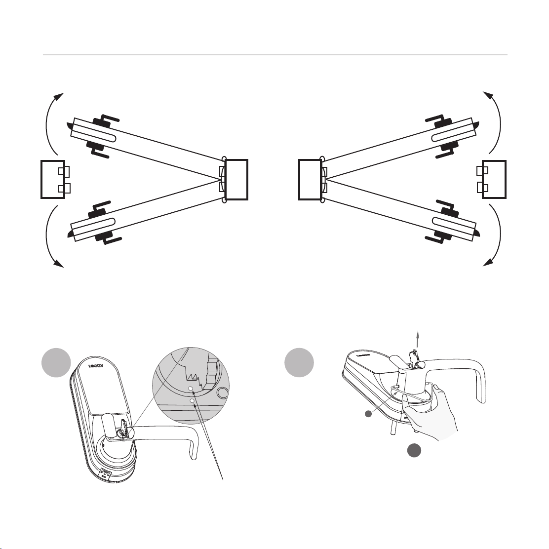
CHANGING HANDLE FOR RIGHT OR LEFT SWING DOORS
Step 2
Changing the Exterior Handle Orientation
(Right handle)
Insert key and rotate lock
face so that the two white
dots align as shown.
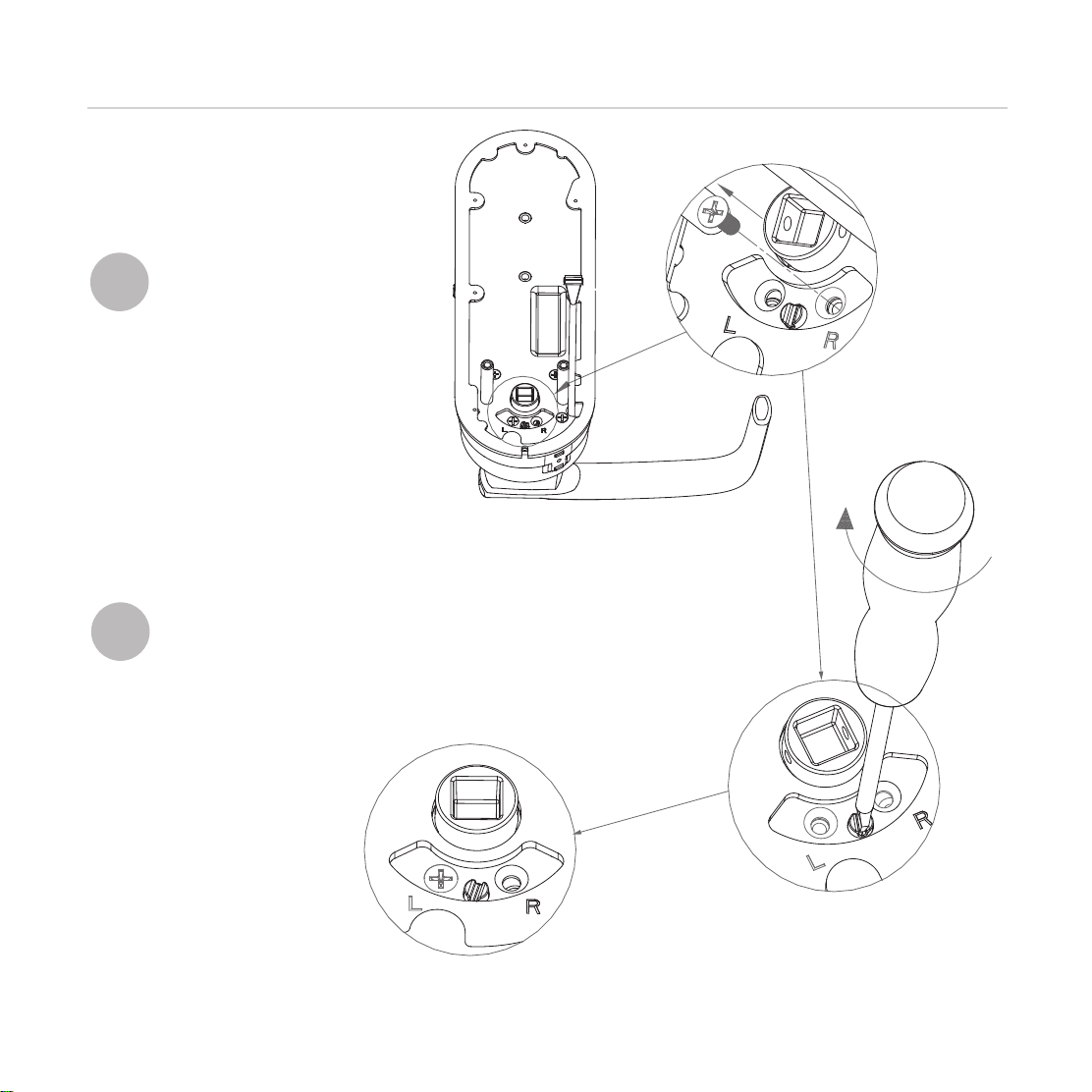
12
R
Use the provided pin insert Rto push the metal
pin located at the 3 o’clock of the the base
handle, then the other pin at 9 o’clock position.
Remove the handle once the pins are
compressed.
The lock ships with handle default for right in-swing or left out-swing door. Check the diagram below
if you are unsure of you door orientation.
Hinge
Side
RIGHT IN-SWING DOOR
LEFT OUT-SWING DOOR RIGHT OUT-SWING DOOR
LEFT IN-SWING DOORINTERIOR
EXTERIOR
No need to change door handle
orientation. Skip Step 2.
LEFT-IN SWING and RIGHT OUT-SWING DOORS
require changing the door handle orientation.
Contnue to follow Step 2 to change exterior
and interior door handle orientation.