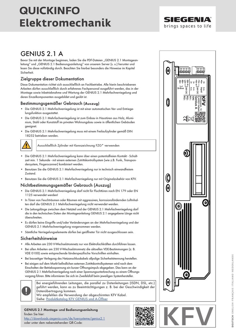
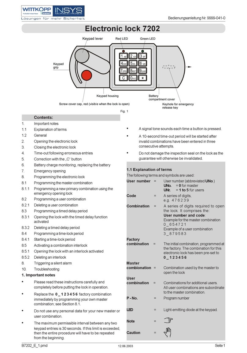
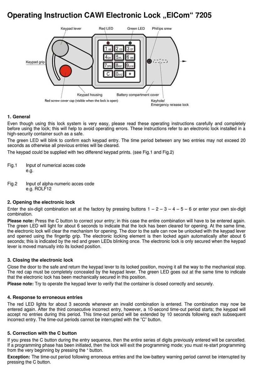
Siegenia KFV BS 6000 OF User manual

ASSEMBLY INSTRUCTIONS
KFV
Multi-point locks,
key operated

02.2019 364
Assembly instrucons
Inhalt
1 INTRODUCTION.........................................4
............................. 4
............. 4
................................................. 4
....................................... 4
........................... 4
................................................. 4
..... 4
....................................................... 5
................................................... 5
................................................ 5
.............................. 6
.............................. 6
................................... 6
..................................... 6
......................................... 6
2 SAFETY.......................................................8
..................... 8
...................................... 8
............................................... 8
..................... 9
3 VARIANTS AND COMPONENTS...............10
.......................................... 10
........ 12
................... 12
.................................... 13
................... 13
.................... 14
................................................... 15
................................................. 15
......................... 15
4 ASSEMBLY BS 6000 OF/OR ......................16
.................................... 16
..................... 18
..................... 19
.............................. 21
........................... 25
.......... 29
............................... 30
............ 31
5 INSTALLATION BS 6000, BS 6600..............32
.............................................. 32
................................ 33
................ 33
........ 34
.................................... 35
..................... 37
..................... 38
.............................. 40
........................... 44
.......... 48
............................... 49
............ 51
6 PERFORMING THE ADJUSTMENTS .........53
.................................. 53
........................................ 54
................... 55
...................................... 56
........... 58
7 FUNCTIONAL TEST...................................60
..................... 60
................... 62
8 TROUBLESHOOTING................................63
...................................... 63
............................................ 63
.................................................. 63
02.2019464
Assembly instrucons
1 Introducon
1.1 Manufacturer and Service
1.2 Target group of this documentaon
1.3 Intended use
1.3.1 Installaon locaon
•
•
•
1.3.2 Locking part and hardware
•
1.4 Improper use
•
•
•
•
•
•
•
1.5 Installaon condions and requirements
•
•
•
•
•
•
•
•

02.2019 564
Assembly instrucons
•
•
1.6 Transport
•
•
•
•
•
1.7 Dimensions
1.8 Symbols used

02.2019664
Assembly instrucons
1.11 Applicable documents
1.12 Appropriate disposal
•
•
1.13 Causes of damage
1.9 Other types of indicators
•
–
f
Cross reference
1.10 Screw recommendaons

02.2019 764
Assembly instrucons

02.2019864
Assembly instrucons
2 Safety
•
2.1 Structure of the warning notes
•
•
•
•
•
SIGNAL WORD
Type and source of danger
•
2.2 Warning notes used
DANGER
WARNING
CAUTION
NOTICE
2.3 Warning notes
CAUTION
Risk of injury due to crushing
•
•
CAUTION
There is a risk of injury from sharp edges
•
CAUTION
Risk of injury from swarf ying around rapidly
•

02.20191064
Assembly instrucons
3 Variants and components
3.1 Delivery opons
BS 6000 OF/OR Use in inacve sash
1
4
5
6

02.20191264
Assembly instrucons
3.2 Size variants BS 6000, BS 6000 OF/OR
3.2.1 PZ dimensions: 92 mm, 94 mm
T
I
A
M
K
X
ATI K
W000 2100 1050 235 235 260 240
1
X
Dimensions I + K
X
M
N

02.2019 1364
Assembly instrucons
3.3 Size variant BS 6600
3.3.1 PZ dimensions: 72 mm, 92 mm
T
I
CB
A
K
X
M
AB C T I K
K600 2100 1050 385 355 235 235 260 240
1
X
Dimensions I + K
X
M
N

02.20191464
Assembly instrucons
3.4 Main lock types, key-operated
Main lock type
Cylinder lock
PZ/RZ
PZ dimen-
sion
[E]
Backset
[D]
Rear backset
[L]
Deadbolt
projecon
[R] [M] [N] [O] [P] [Q] [S]
PZ 72 55 17.5 20 29 57.5 12.5 51.5 47 12
HPZ 92 35 17.5 16 29 57.5 12.5 31.5 47 12
HPZ 92 17.5 20 29 57.5 12.5 31.5 47 12
H 94 35 20.3 16 29 57.5 12.5 29.5 47 12
H 94 20.3 20 29 57.5 12.5 29.5 47 12
Figure: PZ Figure: RZ
D L
R
S
M
E
ON
Q
P
6,5
53,5
3*
D L
E
P

02.20191664
Assembly instrucons
4 Assembly BS 6000 OF/OR
4.1 Milling the door leaf
CAUTION
There is a risk of injury from swarf
•
12.
A
T
I
K
1
2
3
Angle gear
15.
1
2
3
D
L
Main lock
14.

02.2019 1764
Assembly instrucons
Prole cylinder
milling
Round cylinder
milling
Cylinders
14.
14
5
2
33

02.20191864
Assembly instrucons
4.2 Measure and crop reducons
CAUTION
There is a risk of injury from sharp edges
•
•
2
3
1
2
f
f
f
f
3
f
f
21
50%
100%
This manual suits for next models
3
Table of contents
Other Siegenia Lock manuals

Siegenia
Siegenia AS 3600 User manual

Siegenia
Siegenia GENIUS 2.2 PANIC User manual

Siegenia
Siegenia GENIUS 2.2 PANIC User manual

Siegenia
Siegenia ALU User manual

Siegenia
Siegenia KFV User manual

Siegenia
Siegenia KFV RB 1200 User manual

Siegenia
Siegenia AEROTUBE WRG smart User manual

Siegenia
Siegenia KFV GENIUS 2.1 PANIC User manual

Siegenia
Siegenia KFV User manual

Siegenia
Siegenia GENIUS 2.1 A User manual