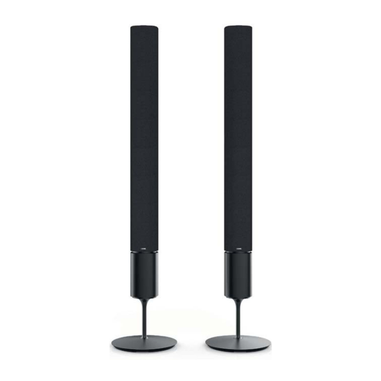
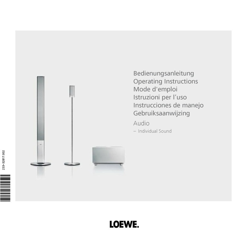
Loewe Individual Sound Projector User manual

SERVICEANLEITUNG SOUND PROJECTOR
Service Manual. Manuel de Service. Manuale di Servizio.
Instrucciones de servicio. Service-instructies.
230- 98287.007
INDIVIDUAL SOUND PROJECTOR
LOEWE INDIVIDUAL
SOUND PROJECTOR
Art.-Nr. 67201

SERVICEANLEITUNG SOUND PROJECTOR
Service Manual. Manuel de Service. Manuale di Servizio.
Instrucciones de servicio. Service-instructies.
CONTENTS
TO SERVICE PERSONNEL 2
FRONT PANEL 3
REAR PANELS 3
REMOTE CONTROL 4
SPECIFICATIONS 5
INTERNAL VIEW 5
SET MENU 6
SERVICE PRECAUTIONS 7
DISASSEMBLY PROCEDURES 7–13
UPDATING FIRMWARE 14–24
SELF DIAGNOSIS FUNCTION (DIAG) 25–42
DISPLAY DATA 43
IC DATA 44–45
BLOCK DIAGRAMS 46–47
PRINTED CIRCUIT BOARDS 48–57
PIN CONNECTION DIAGRAM 58
SCHEMATIC DIAGRAMS 60–70
EXPLODED VIEW OVERALL ASSEMBLY 71
PACKING PARTS 72
PACKING ASSY 73
WIRING EXTERNAL 74-76
ADJUSTING SYSTEM PARAMETERS 77–79
When transporting this unit, be sure to use the unit’s packing materials and box so
as to protect it against any damage, in particular, dents in the front grille during
transportation.
1

SOUNDPROJECTOR
2
WARNING: CHEMICAL CONTENT NOTICE!
The solder used in the production of this product contains LEAD. In addition, other electrical/electronic and/or plastic (where
applicable) components may also contain traces of chemicals found by the California Health and Welfare Agency (and
possibly other entities) to cause cancer and/or birth defects or other reproductive harm.
DO NOT PLACE SOLDER, ELECTRICAL/ELECTRONIC OR PLASTIC COMPONENTS IN YOUR MOUTH FOR ANY REA-
SON WHATSOEVER!
Avoid prolonged, unprotected contact between solder and your skin! When soldering, do not inhale solder fumes or expose
eyes to solder/flux vapor!
If you come in contact with solder or components located inside the enclosure of this product, wash your hands before
handling food.
WALL
OUTLET
EQUIPMENT
UNDER TEST
AC LEAKAGE
TESTER OR
EQUIVALENT
INSULATING
TABLE
■TO SERVICE PERSONNEL
1. Critical Components Information
Components having special characteristics are marked s
and must be replaced with parts having specifications equal
to those originally installed.
2. Leakage Current Measurement (For 120V Models Only)
When service has been completed, it is imperative to verify
that all exposed conductive surfaces are properly insulated
from supply circuits.
●Meter impedance should be equivalent to 1500 ohms shunted
by 0.15μF.
●Leakage current must not exceed 0.5mA.
●Be sure to test for leakage with the AC plug in both
polarities.
“CAUTION”
“F501: FOR CONTINUED PROTECTION AGAINST RISK OF FIRE, REPLACE ONLY WITH SAME TYPE 5A, 125V FUSE.”
CAUTION
F501: REPLACE WITH SAME TYPE 5A, 125V FUSE.
ATTENTION
F501: UTILISER UN FUSIBLE DE RECHANGE DE MEME TYPE DE 5A, 125V.
注意:
All of the P.C.B.s installed in this unit are soldered using
the lead free solder.
Among some types of lead free solder currently available,
it is recommended to use one of the following types for the
repair work.
• Sn + Ag + Cu (tin + silver + copper)
• Sn + Cu (tin + copper)
• Sn + Zn + Bi (tin + zinc + bismuth)
Caution:
As the melting point temperature of the lead free solder
is about 30°C to 40°C (50°F to 70°F) higher than that of
the lead solder, be sure to use a soldering iron suitable
to each solder.
About Lead Free Solder / 無鉛ハンダについて

SP-1
3
FRONT VIEW
REAR VIEW

3 -
REMOTE CONTROL ASSIST
Switch on/off on standby................................. (page 13)
Switch over to operate TV Radio Digital
Switch over to operate Sound Projector
Sound mode .................................................... (page 20)
Loewe TV: Numbers or letters
Loewe TV: Numbers or characters
Input source (TV, AUX 1, 2, 3).......................... (page 19)
Surround mode................................................ (page 22)
Short: Channel volume; long: Menu language selection
Short: Hide menu
Long: Special Functions 1................................. (page 24)
Loewe TV: Station up/down
MENU: Select/Set
1) Only for specialist staff
Sound field programme "Sport"....................... (page 22)
Sound field programme off.............................. (page 22)
¾
¾
¾
¾Loewe TV: Function depending on model
Sound on / off
LED indicator for current operating mode
Switch over to operate TV
Switch over to operate DVD recorder/Auro
(page 21).............. Input mode AUTO, DTS or ANALOGUE
(page 23).......................................................Night mode
(page 23)........................................................ Bass mode
(page 23).........Short: Test sound for loudspeaker setting;
(page 13, 17)....................................... Long: Auto set-up
(page 24).......................................... Short: Sound menu;
(page 20).........................................Long: Menu Memory
(page 19)............................................................. Volume
MENU: Confirm menu selection
(page 22)..........................Sound field programme "Film"
(page 22)....................... Sound field programme "Music"
¾
¾
¾
SP-1
4
Control-Button:
OK = Enter
End = Return

SP-1
5
■INTERNAL VIEW
• DIMENSIONS/寸法図
■SPECIFICATIONS / 参考仕様
63 4 5 7
1DRIVER, WOOFER
2DRIVER, TWEETER
3OPERATION (3) P.C.B.
4OPERATION (4) P.C.B.
5INPUT (3) P.C.B.
6OPERATION (1) P.C.B.
7OPERATION (2) P.C.B.
8AMP (2) P.C.B.
9DSP P.C.B.
0AMP (1) P.C.B.
AINPUT (2) P.C.B.
BINPUT (1) P.C.B.
Front view
Rear view
Shield unit
2
2 11
8 9
A B
0
■Amplifier Section/ア
Maximum Power (EIAJ)
Woofer [3 ohms, 100 Hz, 10% THD] ................................ 20 W/ch
Tweeter [4 ohms, 1 kHz, 10% THD] ................................... 2 W/ch
Total Maximum Output Power
........................................................................................... 120 W
Minimum RMS Output Power /
Woofer [3 ohms, 100 Hz, 0.9% THD] ............................... 14 W/ch
Tweeter [4 ohms, 1 kHz, 0.9% THD] ............................... 1.7 W/ch
Input Sensitivity/Impedance / 入力感度/インピーダンス
Analog input ....................................................... 1.0 V / 32 k-ohms
Maximum Input Signal / 最大許容入力 [1 kHz, 0.5% THD]
Analog input .............................................................. 2.2 V or more
Output Level/Impedance / 出力電圧/出力インピーダンス
Woofer PRE OUT ............... 1.5 V / 1.1 k-ohms (less than 120 Hz)
Total Harmonic Distortion / 全高調波歪率 [1 W]
Woofer [100 Hz] .......................................................... 0.2% or less
Tweeter [1 kHz] ........................................................... 0.1% or less
■Video Section/ビデオ部
Output Level
Composite video .................................................... 1 Vp-p/75 ohms
Component video Y ............................................. 1 Vp-p/75 ohms
Pb, Pr .................................. 0.5 Vp-p/75 ohms
Frequency Characteristics
Composite video ........................................................ 5 Hz-10 MHz
Component video ...................................................... 5 Hz-60 MHz
■Speaker Section/スピーカー部
Type / 型式 ............................................... 2-way acoustic suspension
Magnetic shielding type
Drivers / スピーカーユニット
Woofer ............................................. 11 cm (4-5/16") cone type x 2
Tweeter ............................................ 4 cm (1-9/16") cone type x 40
Frequency Response / 再生周波数帯域 ................. 55 Hz to 20 kHz
Crossover Frequency / クロスオーバー周波数
Beam channel ...................................................................... 350 Hz
Stereo channel ....................................................................... 1 kHz
■Input/Output/入力/出力
Input Jack / 入力端子
Audio ......................... VCR, TV/STB
Digital (optical) [Fs=32/44.1/48/64/88.2/96 kHz]
................................... TV/STB, AUX / DVD
Digital (coaxial) [Fs=32/44.1/48/64/88.2/96 kHz]
....................................................................................DVD / AUX
Video (composite)
....... TV/STB, VIDEO, AUX / DVD
U, C, K, V, J models ........................................................... NTSC
T, A, B, G, E, L models .......................................................... PAL
Component video
................................... TV/STB, DVD
Output Jack /出力端子
Video (composite)
U, C, K, V, J models ........................................................... NTSC
T, A, B, G, E, L models .......................................................... PAL
Component video .............................................. Selected video out
Subwoofer ....................................................................... PRE OUT
Microphone Input Jack /マイク入力
..................... Automated system calibration
Rmote Input/Output /リモート入力/出力
Input ................................................................................ Remote in
RS-232C
Output ........................................................... IR out (pass through)
■General/総合
Power Supply/電源電圧
U, C models .......................................................... AC 120 V, 60 Hz
T model ................................................................. AC 220 V, 50 Hz
K model................................................................. AC 220 V, 60 Hz
A model................................................................. AC 240 V, 50 Hz
B, G, E models ..................................................... AC 230 V, 50 Hz
L model .................................................... AC 220-240 V, 50/60 Hz
V model.................................................... AC 110-120 V, 50/60 Hz
J model ............................................................ AC 100V, 50/60 Hz
Power Consumption/消費電力 .............................................. 50 W
Standby Power Consumption (Reference Data考値)
................................................................................ 0.1 W or less
Dimensions/寸法 (W x H x D)
...................... 1030 x 194 x 118 mm (40-9/16" x 7-5/8" x 4-5/8")
Weight/質量 ................................................ 13.0 kg (28 lbs. 10 oz.)
Finish/仕上げ
Silver color .....................................................67201T00 / 67201T80
Black color .................................................. 67201W00 / 67201W80
Accessories/付属品
Remote control x 1, Batteries (UM-3) x 2, Power cable x 1, Video pin
cable x 1, Audio pin cable x 2, Digital audio pin cable x 1, Optical
cable x 1, Cable clip x 1, Fastener x 4, Optimizer microphone x 1,
Cardboard microphone stand x 1, DVD-ROM x 1 (J model)
U .......... U.S.A. model C ...... Canadian model
T .......... Chinese model K ...... Korean model
A .......... Australian model B ...... British model
G .......... European model E ...... South European model
L ........... Singapore model V ...... Taiwan model
J ........... Japanese model
* Specifications are subject to change without notice due to product
improvements.
TruBass, SRS and the “ ” symbol are registered trademarks of
SRS Labs, Inc. TruBass technology is incorporated under license from
SRS Labs, Inc.
TruBass、SRS SRSLab,Inc.
TruBass SRSLabs,Inc.
AAC
The “ ” logo and “IntelliBeam” are trademarks of YAMAHA
Corporation.
「IntelliBeam」
The “ ” logo and “Cinema DSP” are registered trademarks of
YAMAHA Corporation.
「DSP」「CINEMADSP」
Manufactured under license from Dolby Laboratories.
“Dolby”, “Pro Logic”, and the double-D symbol are trademarks of Dolby
Laboratories.
「PROLOGIC」
“DTS”, and “Neo:6” are trademarks of Digital Theater Systems, Inc.
DTS Neo:6
Manufactured under license from 1 Ltd. Worldwide patents applied for.
The ‘ ’ logo and ‘Digital Sound Projector™’ are trademarks of 1 Ltd.
DigitalSoundProjectorTM1Ltd
118 (4-5/8")
194 (7-5/8")
1030 (40-9/16")
Unit : mm (inch)
単位:mm(インチ)
160 (6-5/16")
34
(1-5/16")
848 (33-3/8")
79
(3-1/8")
41
(1-5/8")
700 (27-9/16")
4-M6
267 (10-1/2") 17 (11/16")
22.5
(7/8")
70
(2-3/4")
48
(1-7/8")
76
(3")
165 (6-1/2")165 (6-1/2")
SP-1
6
■SET MENU TABLE / セットメニュー
TRBL (0.5 dB step -12.0 to 0 to +12.0 [dB])
BASS (0.5 dB step -12.0 to 0 to +12.0 [dB])
FRONT, SWFR
80, 100, 120 [Hz]
-20 to 0 [dB]
0.3 to 15.0 [m] (0.1 step)
1.0 to 50.0 [ft] (0.5 step)
SHELF, WALL
[NORMAL], HI ECHO
FLAT TO WALL, ANGLE TO WALL OR CORNER
0.0 to 3.0 [m] (0.1 step)
0.0 to 10.0 [ft] (0.5 step)
2.0 to 12.0 [m] (0.1 step)
6.5 to 40.0 [ft] (0.5 step)
2.0 to 12.0 [m] (0.1 step)
6.5 to 40.0 [ft] (0.5 step)
1.8 to 9.0 [m] (0.1 step)
6.0 to 30.0 [ft] (0.5 step)
0.6 to 11.4 [m] (0.1 step)
2.0 to 38.0 [ft] (0.5 step)
H.ANGLE FL (1 deg. step -90 deg to 0 to +90 deg)
H.ANGLE FR (1 deg. step -90 deg to 0 to +90 deg)
H.ANGLE C (1 deg. step -90 deg to 0 to +90 deg)
H.ANGLE SL (1 deg. step -90 deg to 0 to +90 deg)
H.ANGLE SR (1 deg. step -90 deg to 0 to +90 deg)
V.ANGLE.FL (1 deg. step -45 deg to 0 to +45 deg)
V.ANGLE.FR (1 deg. step -45 deg to 0 to +45 deg)
V.ANGLE.C (1 deg. step -45 deg to 0 to +45 deg)
V.ANGLE.SL (1 deg. step -45 deg to 0 to +45 deg)
V.ANGLE.SR (1 deg. step -45 deg to 0 to +45 deg)
DIST FL (0.1 m step 0.3 to 24.0 [m])
(0.5 ft step 1.0 to 80.0 [ft])
DIST FR (0.1 m step 0.3 to 24.0 [m])
(0.5 ft step 1.0 to 80.0 [ft])
DIST C (0.1 m step 0.3 to 24.0 [m])
(0.5 ft step 1.0 to 80.0 [ft])
DIST SL (0.1 m step 0.3 to 24.0 [m])
(0.5 ft step 1.0 to 80.0 [ft])
DIST SR (0.1 m step 0.3 to 24.0 [m])
(0.5 ft step 1.0 to 80.0 [ft])
F.L. FL (0.1 m step -1.0 to 13.0 [m])
(0.5 ft step -3.5 to 43.5 [ft])
F.L. FR (0.1 m step -1.0 to 13.0 [m])
(0.5 ft step -3.5 to 43.5 [ft])
F.L. C (0.1 m step -1.0 to 13.0 [m])
(0.5 ft step -3.5 to 43.5 [ft])
F.L. SL (0.1 m step -1.0 to 13.0 [m])
(0.5 ft step -3.5 to 43.5 [ft])
F.L. SR (0.1 m step -1.0 to 13.0 [m])
(0.5 ft step -3.5 to 43.5 [ft])
TRBL FL (0.5 dB step -12.0 to 0 to +12.0 [dB])
TRBL FR (0.5 dB step -12.0 to 0 to +12.0 [dB])
TRBL C (0.5 dB step -12.0 to 0 to +12.0 [dB])
TRBL SL (0.5 dB step -12.0 to 0 to +12.0 [dB])
TRBL SR (0.5 dB step -12.0 to 0 to +12.0 [dB])
L | · · · · · · · · C 0 to 95 [%] (5% step) (* 5)
C · · · · · · · · | R 0 to 95 [%] (5% step) (* 5)
[TV], VIDEO
DVD, [AUX] U, C, T, K, A, B, G, E, L, V models
[DVD], AUX J model
[DVD], AUX U, C, T, K, A, B, G, E, L, V models
DVD, [AUX] J model
TV, [VCR] U, C, T, K, A, B, G, E, L, V models
[TV], VCR J model
DVD, [AUX] U, C, T, K, A, B, G, E, L, V models
[DVD], AUX J model
DVD, [AUX] U, C, T, K, A, B, G, E, L, V models
[DVD], AUX J model
· · · · | · · · · (0.5 dB step -6.0 to 0.0 [dB])
(* 12) A-Z, a-z, 0-9
-2, -1, OFF
DISPLAY OFF, -3, -2, -1, OFF
-5 to 0 to +5 (1 step)
BLUE, GRAY
1
2
3
4
5
MEMORY
AUTO SETUP
MANUAL SETUP
LANGUAGE SET (* 11)
1) LOAD
2) SAVE
1) BEAM+SOUND OPTIMZ
2) BEAM OPTIMZ ONLY
3) SOUND OPTIMZ ONLY
1) SOUND MENU
2) BEAM MENU
3) INPUT MENU
4) DISPLAY MENU
A) TONE CONTROL
B) SUBWOOFER SET
C) MUTE LEVEL
D) AUDIO DELAY
E) ROOM EQ
F) DD/DTS DYNAMIC RANGE
A) SETTING PARAMETERS
B) BEAM ADJ
C) IMAGE LOCATION
A) INPUT ASSIGNMENT (* 10)
B) INPUT MODE
C) INPUT TRIM
D) INPUT RENAME (* 11)
A) DIMMER SET
B) OSD SET
C) UNIT SET
CATEGORY 1 MAIN MENU 2 SUB MENU 3
TREBLE
BASS
BASS OUT
CROSS OVER
LFE LEVEL
DISTANCE
MUTE, -20 dB
0 to 160 mS
MOUNTING
REFLECTING
MIN, STD, MAX
INSTALLED POSITION
INSTALLED HEIGHT
ROOM WIDTH
(C: LEFT WALL)
ROOM LENGTH
(C: RIGHT WALL)
USER POSITION
TO L WALL (* 4)
a) HORIZONTAL ANGLE (* 5)
b) VERTICAL ANGLE (* 5)
c) BEAM TRAVEL LENGTH
d) FOCAL LENGTH (* 5)
e) TREBLE GAIN
ON, OFF
LEFT
RIGHT
OPTICAL IN (1)
OPTICAL IN (2)
COAXIAL IN
COMPONENT IN (1)
COMPONENT IN (2)
COMPOSITE IN
AUTO, LAST
OPTICAL IN (1) TV ANALOG
OPTICAL IN (2) OPTICAL
COAXIAL IN VCR ANALOG
ANALOG IN (1) AUX OPTICAL
ANALOG IN (2) DVD COAXIAL
DVD - > _ DVD
STANDARD DIMMER
AUTO DIMMER
OSD SHIFT
OSD BACK COLOR
SELECT MENU 4 VALUE [INITIAL]
ENGLISH, DEUTSCH, Francais, ESPANOL
*4 ..... Displayed only for the FLAT TO WALL setting; distance from the wall on the left side to the user.
*5 ..... Test tone output.
*10 ... Priority given to COAXIAL when set to the same input. / COAXIAL
*11 ... Displayed only for the U, C, T, K, A, B, G, E, L, V models.
*12 ... MAX 8 Character.
MEMORY 1, MEMORY 2, MEMORY 3
METERS, FEET (U, C, T, K, A, B, G, E, L, V models)

SP-1
7
■DISASSEMBLY PROCEDURES /順
(Remove parts in the order as numbered.)
Cautions for disassembly and reassembly :
• Disconnect the power cable from the AC outlet.
• Spread soft cloth or the like and perform the work on it.
• Use full care as you may be injured by the front grille
or other part.
• All screws must be tightened securely to prevent air
leakage. Check the number of screws and their
positions when installing them.
• When installing parts, be careful not to have anything
such as cables caught between other parts.
• Make sure that all the removed driver (tweeter) parts
are reinstalled at specified positions.
■SERVICE PRECAUTIONS / サービス時の注意事項
安全対策Safety measures
• Some internal parts in this product contain high voltages
and are dangerous. Be sure to take safety measures
during servicing, such as wearing insulating gloves.
• Note that C523 on the INPUT (1) P.C.B. is dangerous
even after the power is turned off because an electric
charge remains and a high voltage continues to exist
there.
Before starting any repair work, perform discharge by
connecting a discharge resistor (5 k-ohms/10 W) between
C523 terminals.
(For the discharge resistor connection points, refer to page
52 “PRINTED CIRCUIT BOARD [INPUT (1) P.C.B.]” and
page 67 “SCHEMATIC DIAGRAM [INPUT 2/2]”)

SP-1
8
Fig. 2
3333
33
3
Rear panel
1. Removal of Top Panels and Plate/Top
a. Remove 8 screws (1). (Fig. 1)
b. Remove 2 top panels.
c. Remove 2 screws (2). (Fig. 1)
d. Remove the plate/top.
1
1
1
1
2
Top panel
Top panel
Plate/ top
Fig. 1
1. トップパネル、プレート/トップの外し方

SP-1
9
2. Removal of Shield Unit
a. Remove 22 screws (3). (Fig. 2)
b. Remove the rear panel.
c. Remove 18 screws (4). (Fig. 3)
d. Remove CB2, CB3, CB4, CB504, CB507 and CB508.
(Fig. 3)
e. Remove 5 pad LNs.
f. Remove the shield unit.
2. シールドユニットの外し方
Fig. A
Fig. 3
When checking the P.C.B. :
• The shield unit removed from the unit does not work
because its grounding is loose. Be sure to connect the
ground of the shield unit to the chassis or GND with a
ground lead or the like. (Fig. A)
• Reconnect all cables (connectors) that have been
disconnected.
• When connecting the cable, use care for the polarity.
P.C.B.チェックをする場合には
CB3
CB2 CB508
CB504
CB507
CB4
Shield unit
Pad LN
4 4 4
44
4
Shield unit
Front panel unit DSP P.C.B.AMP (R) P.C.B. AMP (L) P.C.B.
Ground lead

SP-1
10
Fig. 4
Fig. 5
3. INPUT(1)、(2)P.C.B.の外し方3. Removal of INPUT (1) and (2) P.C.B.s
a. Remove 6 screws (5), 8 screws (6) and 2 jack screws (7).
(Fig. 4)
b. Remove CB4. (Fig. 4)
c. Remove the INPUT (2) P.C.B..
d. Remove 6 screws (8) and 2 screws (9). (Fig. 4)
e. Remove the INPUT (1) P.C.B..
4. DSPP.C.B.、AMP(L)、(R)P.C.B.の外し方4. Removal of DSP P.C.B., AMP (L) and (R) P.C.B.s
a. Remove 4 screws (0). (Fig. 5)
b. Remove CB6, CB7, CB8 and CB9. (Fig. 5)
c. Remove DSP P.C.B..
d. Remove 8 screws (A). (Fig. 5)
e. Remove CB507, CB509, CB510, CB511, CB512, CB707,
CB709, CB710, CB711 and CB712. (Fig. 5)
f. Remove the AMP (L) and (R) P.C.B.s.
CB4
Shield unit
8
576 89
5
INPUT (1) P.C.B.INPUT (2) P.C.B.
0
0
CB510
CB7
CB6
CB709 CB710
CB512 CB511 CB507
A
A
A
A
CB509 CB502
CB8 CB9
CB707CB702 CB712CB711
DSP P.C.B. AMP (L) P.C.B.AMP (R) P.C.B.
R ch L ch

SP-1
11
5. フロントパネルユニットの外し方5. Removal of Front Panel Unit
a. Remove 4 screws (B). (Fig. 6)
b. Remove 2 cover FPs.
c. Remove CB3 and CB303. (Fig. 6)
d. Remove 4 screws (C). (Fig. 6)
e. Remove 2 cover BTMs.
f. Remove 12 screws (D). (Fig. 6)
g. Remove the front panel unit.
Fig. 7
Fig. 8
Fig. 6
7. Removal of Driver (Tweeter)
a. Remove 12 screws (H). (Fig. 8)
b. Remove 2 supports/DSP and 2 supports/DSP C. (Fig. 9)
c. Remove the sound absorbing material.
d. Remove 2 screws/piece marked (I). (Fig. 10)
e. Remove the driver (tweeter).
7. スピーカーユニット(ツイーター)の外し方
6. OPERATION(1)、(3)、(4)P.C.B.の外し方6. Removal of OPERATION (1), (3) and (4) P.C.B.s
a. Remove 6 screws (E). (Fig. 7)
b. Remove CB1. (Fig. 7)
c. Remove the OPERATION (1) P.C.B..
d. Remove 4 screws (F). (Fig. 7)
e. Remove CB301. (Fig. 7)
f. Remove the OPERATION (3) P.C.B..
g. Remove 4 screws (G). (Fig. 7)
h. Remove CB302. (Fig. 7)
i. Remove the OPERATION (4) P.C.B..
CD DDBB
D
Front panel unit
Cover FP
CB3 CB303
Cover BTM Cover BTMCover FP
C
F GGE
OPERATION (3) P.C.B.
OPERATION (4) P.C.B.OPERATION (1) P.C.B.
CB1
CB301
CB302
H H H
H H H H
H
Top view
Bottom view

SP-1
12
Installation of Driver (Tweeter)
Caution : Make sure that all the removed driver (tweeter)
parts are reinstalled at specified positions.
(Fig. B)
スピーカーユニット(ツイーター)の取り付け方
Fig. 10
Fig. B
I
Sound absorber
Support/ DSP Support/ DSPSupport/ DSP C
Fig. 9
A1
B1
A2
B2
C1
A3
B3
C2
A4
B4
C3
A5
B5
C4
A6
B6
C5
A7
B7
C6
A8
B8
C7
A9
B9
C8
A10
B10
C9
A11
B11
C10
A12
B12
C11
A13
B13
A14
B14
A15
Rear view
Rch side Lch side
CB510
CB512 CB511 CB709 CB710
CB509 CB711 CB712
Lch side / Lch側
Pin No. CB509
1–2
3–4
5–6
7–8
9–10
C5
B6
C4
B5
C3
B4
C2
B3
C1
B2
C9
C8
C7
B8
C6
B13
C11
B12
C10
B11
A9
B9
A10
B10
A11
A12
A13
A14
B14
A15
A1
B1
A2
A3
A4
CB510 CB511 CB512 CB709 CB710 CB711 CB712
Rch side / Rch側
A5
A6
A7
B7
A8

SP-1
13
8. Removal of Driver (Woofer)
a. Remove 4 screws (J). (Fig. 11)
b. Remove the side covers L/R.
c. Remove the plate/cover.
d. Remove 4 screws (K). (Fig. 11)
e. Remove the plate/side.
f. Remove 18 screws (L). (Fig. 11)
g. Remove the front grille.
h. Remove 16 screws (M). (Black color model) (Fig. 11)
i. Remove the grille ass’y. (Black color model)
j. Remove 8 screws (N). (Fig. 11)
k. Remove the driver (woofer).
8. スピーカーユニット(ウーファー)の外し方
Fig. 11
L
L
M
M
N
N
J
J
K
K
K
K
Side cover L
Side cover R
Plate side
Plate side
Plate cover
Plate cover
Front grille
Grille ass'y (Black color model)
Driver, woofer
Driver, woofer

SP-1
14
●操作前の準備と注意
• RS232C cross cable “D-sub 9 pin female”
(Specifications)
Pin No.2 RxD Pin No.2 RxD
Pin No.3 TxD Pin No.3 TxD
Pin No.5 GND Pin No.5 GND
Pin No.7 RTS Pin No.7 RTS
Pin No.8 CTS Pin No.8 CTS
●Preparation and precautions before starting
the operation
• Download DSP_FLASHER(YSP).exe and
spDownloader_2_0_x_xxx.exe from the specified
source to the PC being used.
• Prepare the above specified RS232C cross cable.
• While writing, keep the other application software on
the PC closed. It is also recommended to keep the
software on the task tray closed as well.
■UPDATING FIRMWARE / ファームウェアーの書き込み
●必要なツール
After replacing the following parts with the replacement
parts, update the firmware.
IC11 of P.C.B. ASS’Y DSP : X8046B00
... Writing of DSP
IC17 of P.C.B. ASS’Y DSP : X8045B00
... Writing of DSP APPLICATION / SPID
IC26 of P.C.B. ASS’Y DSP : X6894A00
... Writing of CPU
●Required tools
• PC with a serial port (RS232C), OS: Windows 98/2000/
Me/XP
• Program upgrading program
There are 2 program upgrading programs.
Writing of CPU : DSP_FLASHER(YSP).exe
Writing of DSP : DSP_FLASHER(YSP).exe
Writing of DSP APPLICATION / SPID
: spDownloader_2_0_x_xxx.exe.
• Firmware
* Be sure to put following 4 firmwares in the same
folder.
CPU ...................................................
DSP .......................................
DSP APPLICATION
......................... ysp2app_YSP2-0_xxxxx_.hex
SPID .................................................. Y10xxxxxx.bin

SP-1
15
●操作方法
●Operation Procedure
Writing of CPU
1. Install DSP_FLASHER(YSP).exe into the PC.
2. Before turning on the power to YSP-1100 and PC, con-
nect between RS232C ports with the RS232C cable
(cross cable). (Fig. 1)
Fig. 2
Bottom view
Reset switch
Fig. 1
Bottom view
RS-232C port
RS-232C cable
Reset switch
3. While pressing the reset switch of YSP-1100, connect
the power cable to the AC outlet. (Fig. 1, 2)
* Use a fine tipped pin or the like to push the reset
switch.
4. Start up DSP_FLASHER(YSP).exe, the screen will ap-
pear as shown below.

SP-1
16
・MOTFILE
・RS232C
5. Select the data to be transmitted and port.
· MOT FILE
Select “SA25_vx.mot”.
· RS232C
Select the port of RS-232C.
Select the port of RS-232C
接続しているRS-232Cポートを選択します
Press this button to open the window
このボタンを押すとウィンドウが開きます
Select the firmware
ファームウェアを選択します
* The port selection varies depending on OS of the PC.
Windows 98/2000/Me ........... COM1-4
Windows XP .......................... COM1-2
As no port other than the above can be used, se-
lect the port using the setting of the PC.
Press this button to start writing
このボタンを押すと
書き込みが開始されます
During downloading
書き込み中
6. Press the [E.P.] button and start writing.

SP-1
17
3. Start up DSP_FLASHER(YSP).exe, the screen will
appear as shown below.
Writing of DSP
1. Install DSP_FLASHER(YSP).exe into the PC.
2. Before turning on the power to YSP-1100 and PC, con-
nect between RS232C ports with the RS232C cable
(cross cable). (Fig. 1)
7. When the program transmission is completed, the
screen appears as shown below.
The press the [OK] button to end the procedure.
8. Disconnect the power cable of YSP-1100 from the AC
outlet.

SP-1
18
・DSPHEXFILE
・RS232C
4. Select “YSP DSP” tag.
5. Select the data to be transmitted and port.
· DSP HEX FILE
Select “YSPx00_verxxxx.hex”.
· RS232C
Select the port of RS-232C.
* The port selection varies depending on OS of the PC.
Windows 98/2000/Me ........... COM1-4
Windows XP .......................... COM1-2
As no port other than the above can be used, se-
lect the port using the setting of the PC.
Select the port of RS-232C
接続しているRS-232Cポートを選択します
Select YSP DSP
YSPDSPを選択します
Press this button to open the window
このボタンを押すとウィンドウが開きます
Select the firmware
ファームウェアを選択します
Press this button
このボタンを押します
6. Press the [RDY] button.

SP-1
19
8. When the program transmission is completed, the
screen appears as shown below.
Change OFF to ON
7. Connect the power cable of YSP-1100 to the AC outlet.
While pressing the “VOL+” key and “VOL-” key of the
YSP-1100, press the “STANDBY/ON” key of the re-
mote control to activate the DIAG function.
1Using the “UP” or “DOWN” key of the remote control,
select the DIAG menu in the figure below.
2Using the “LEFT” or “RIGHT” key of the remote
control, select the DIAG sub-menu in the figure
below.
3Using the “ENTER” key of the remote control, make
a change as shown below.
During downloading
書き込み中
Other manuals for Individual Sound Projector
2
Table of contents
Other Loewe Speakers System manuals

Loewe
Loewe Individual Sound Projector User manual

Loewe
Loewe 3D Orchestra 5.1 IS User manual

Loewe
Loewe klang bar3 mr User manual

Loewe
Loewe Tremo User manual

Loewe
Loewe INLAYS SOUNDVISION User manual

Loewe
Loewe Individual Sound Projector User manual

Loewe
Loewe SoundPort User manual

Loewe
Loewe Reference Sound Subwoofer User manual

Loewe
Loewe 3D Orchestra 5.1 IS User manual

Loewe
Loewe Reference Sound Standspeaker Slim User manual